


Leaderboard
-

siteunseen
Free Member3Points15,083Posts -
Patcon
 Subscriber
 2Points11,100Posts
 -
Terrapin Z
Subscriber2Points1,329Posts -

Zup
Free Member1Points1,163Posts


Popular Content
Showing content with the highest reputation on 01/30/2022 in Posts
-
I dont recall ever seeing that shielding. Maybe somebody can post up a picture. You could possibly fabricate a replacement if you knew what the original looked like1 point
-
1 pointThere IS a RH factory replica available. https://www.ebay.com/itm/154785975290?hash=item2409f68bfa:g:rPYAAOSweEFbCevK1 point
-
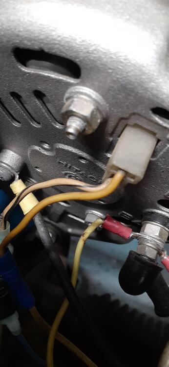
1 point@Zed Head is correct on the wiring. Car yellow to new connector green Car white/black to new connector yellow. Here's a photo from my 73.
 1 point
 -
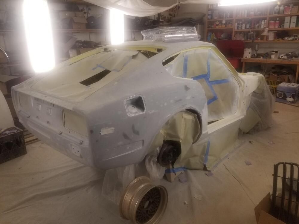
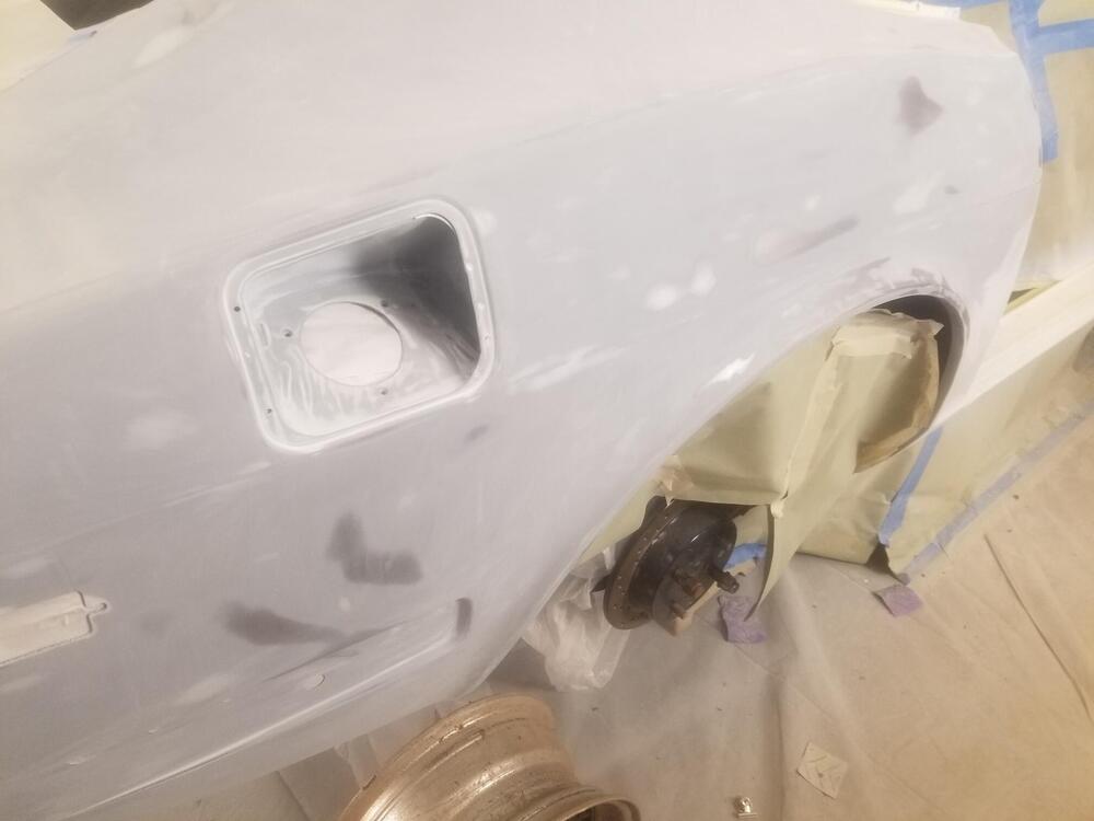
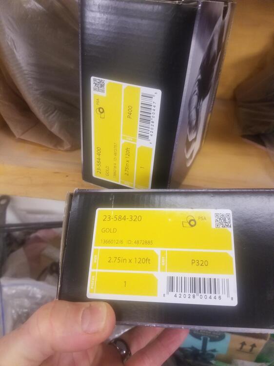
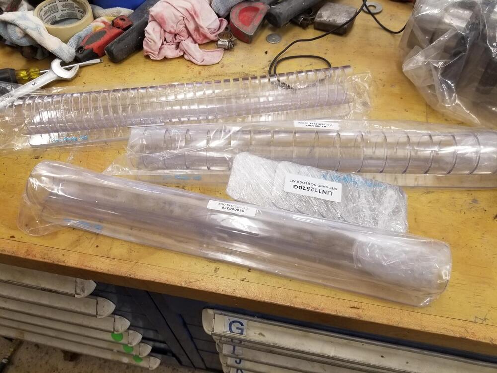
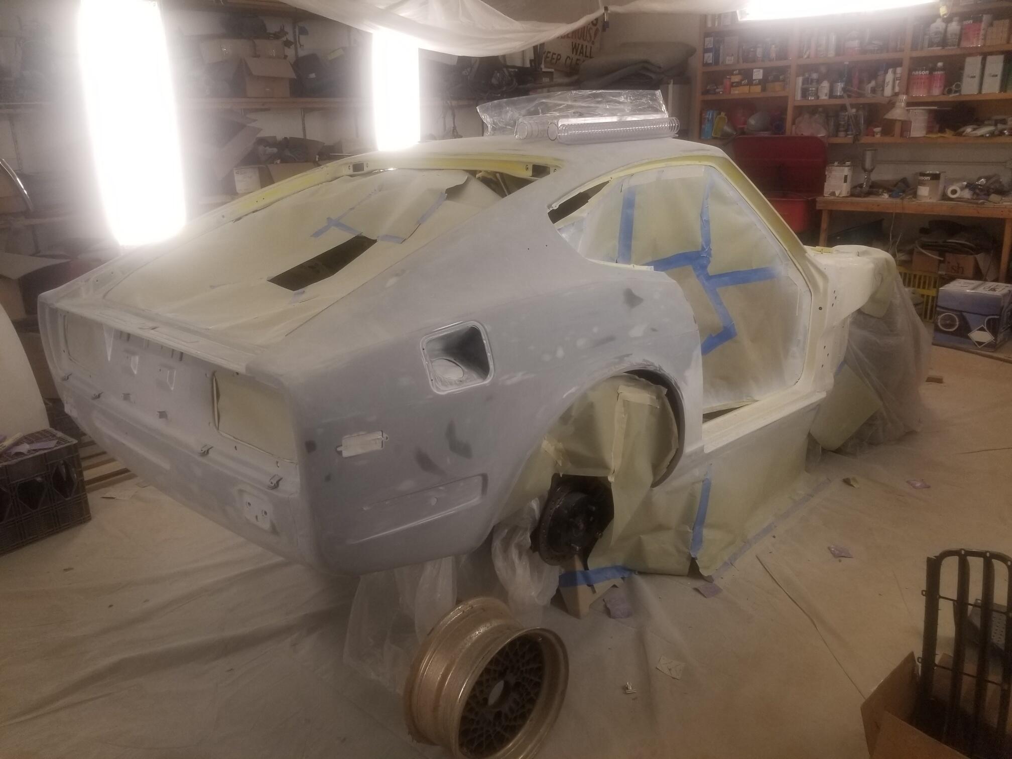
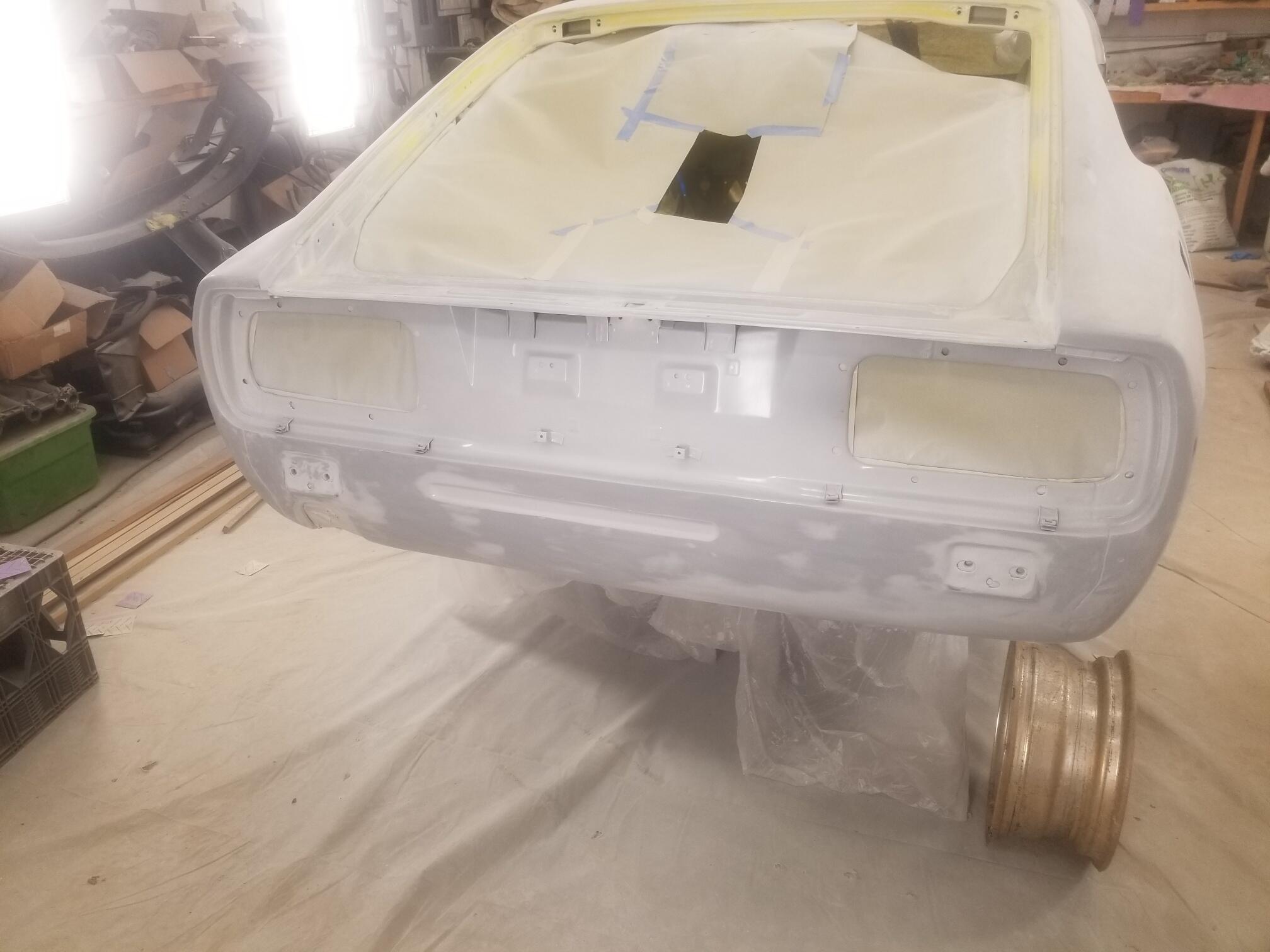
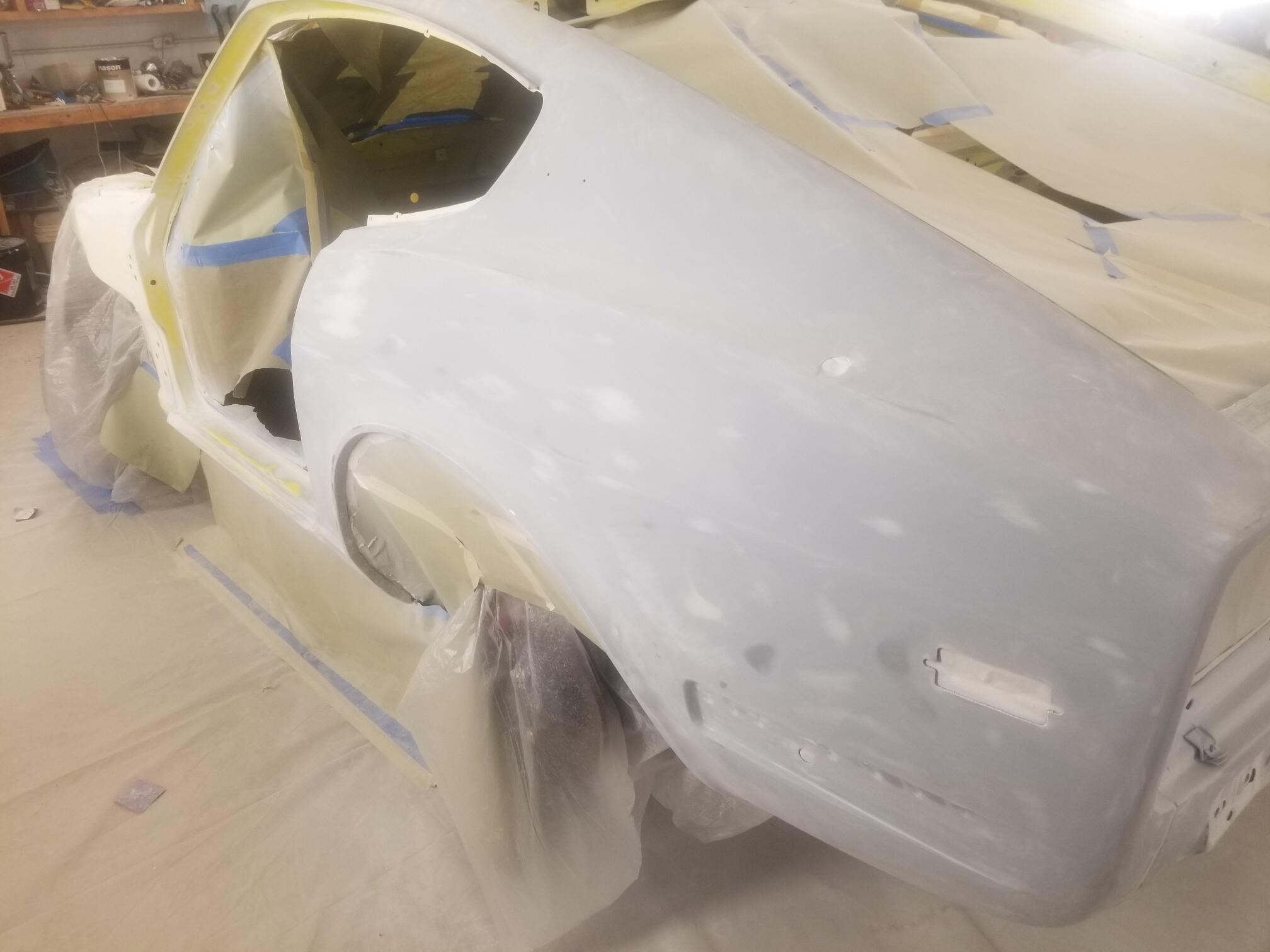
1 pointSo here is where I'm currently at Most of the sealer is off the big surfaces. Still a lot of detail work to do! I just don't think I can get my shop up to temp and keep it there for painting. My shop is concrete filled block walls and floor. Totally uninsulated. There is an incredible amount of thermal mass to try to heat up and hold at temperature when it's 40dF outside. So I think for now I will switch gears and try to work on some other aspects of the car since it's too cold for me to paint. Possibly brakes, differential, drive train or other systems that I can bag up and keep clean while painting. This isn't my preferred method but it would allow some progress while it's cold outside... When I do get back to paint, I have some new blocks to try and some Mirka PSA paper


 1 point
 -
It was all my fault. It's cold here and I was bored. Too much of this1 point
-
1 pointHello Kats, For me, the mid to late 1960's and very early 1970's was the peak of car design in Japan, with great looking models and performance (even those with less performance still looked great). The S30 family is no exception, but I hark more to the rarer/less produced models within the range. Ahh, the late model RS30Q....! Silvia, it's going fine, though slowly. Your statement (I quoted above) can easily fit into it with finding spares for a production run only about 100 more than the Z432. I had been looking for a pair of seats for about 12 years, and finally I brought with a small fortune considering they were for restoration only.1 point
-
Okay it gets to the Xs and Ys. Hermaphrodite dogs! Damn... https://www.petplace.com/article/dogs/pet-health/hermaphrodite-and-pseudohermaphrodite-in-dogs/ This thread went to the wild side. I'm sorry my Dutch friend but some lobe in my brain isn't in the right place.1 point
-
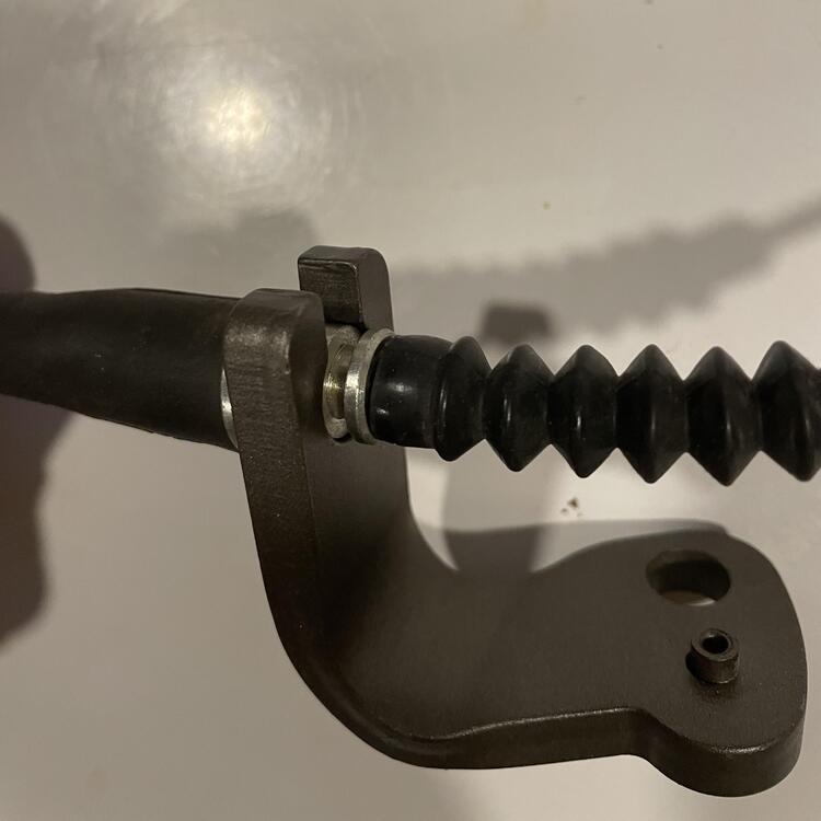
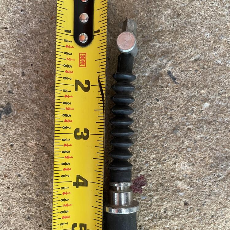
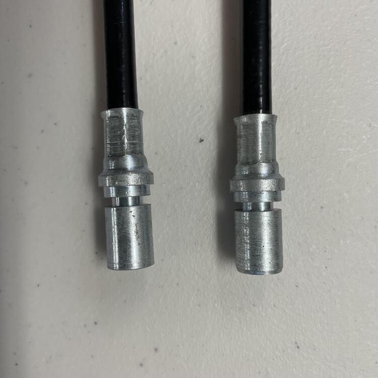
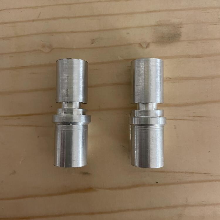
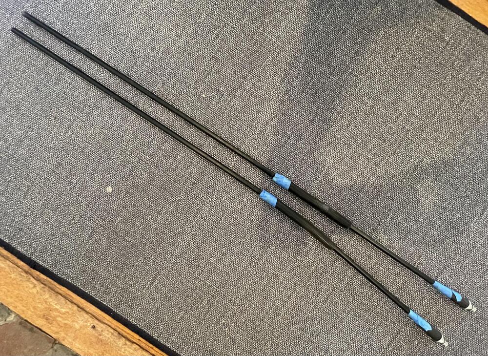
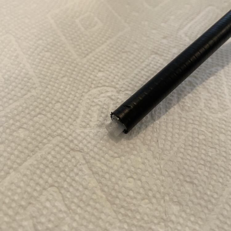
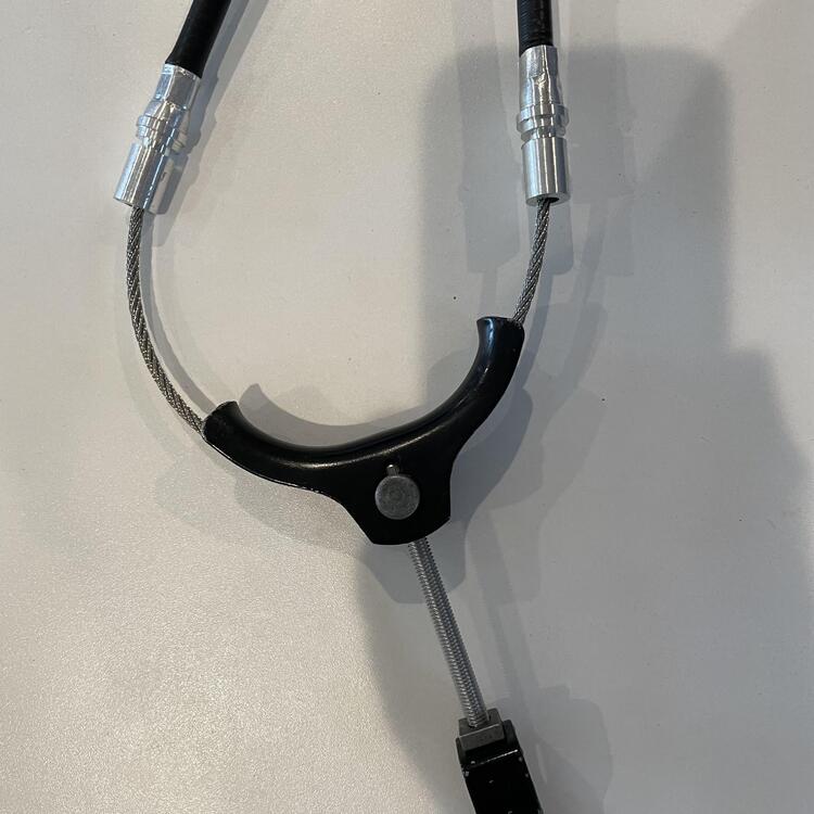
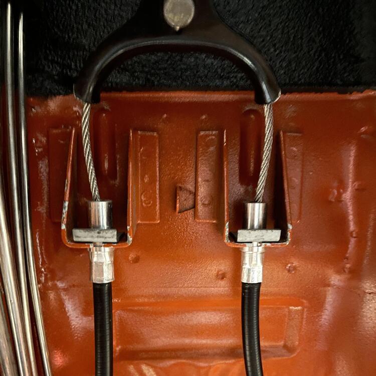
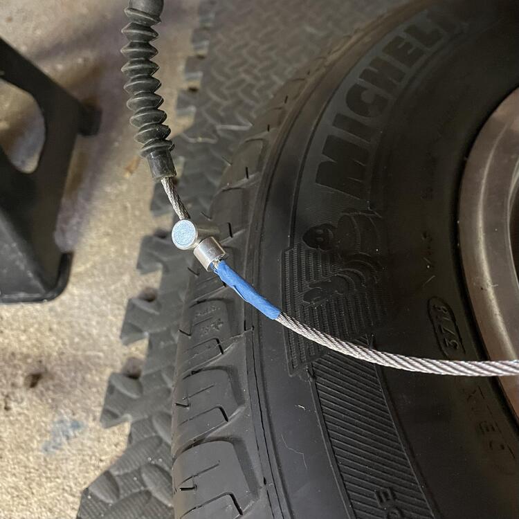
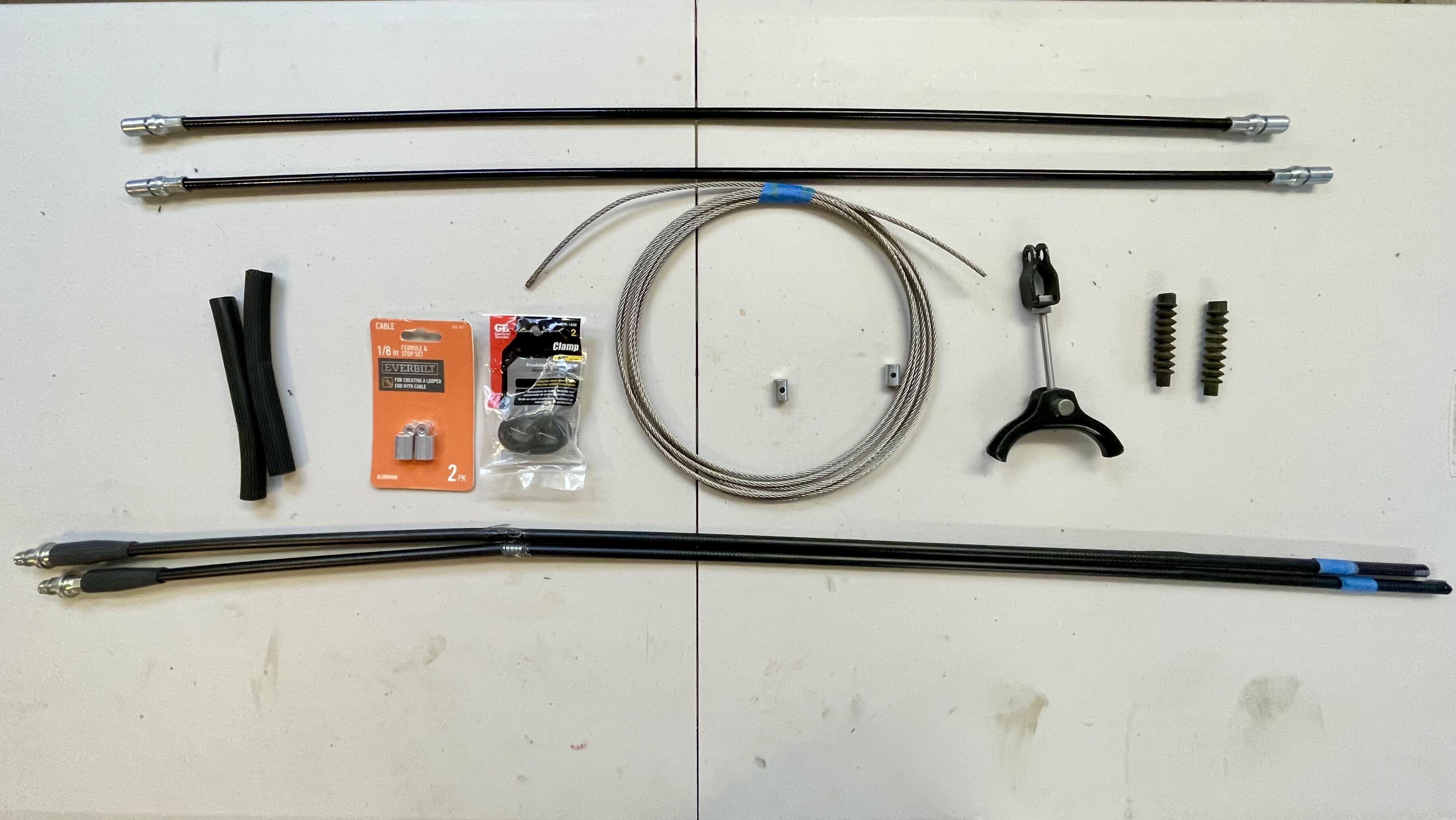
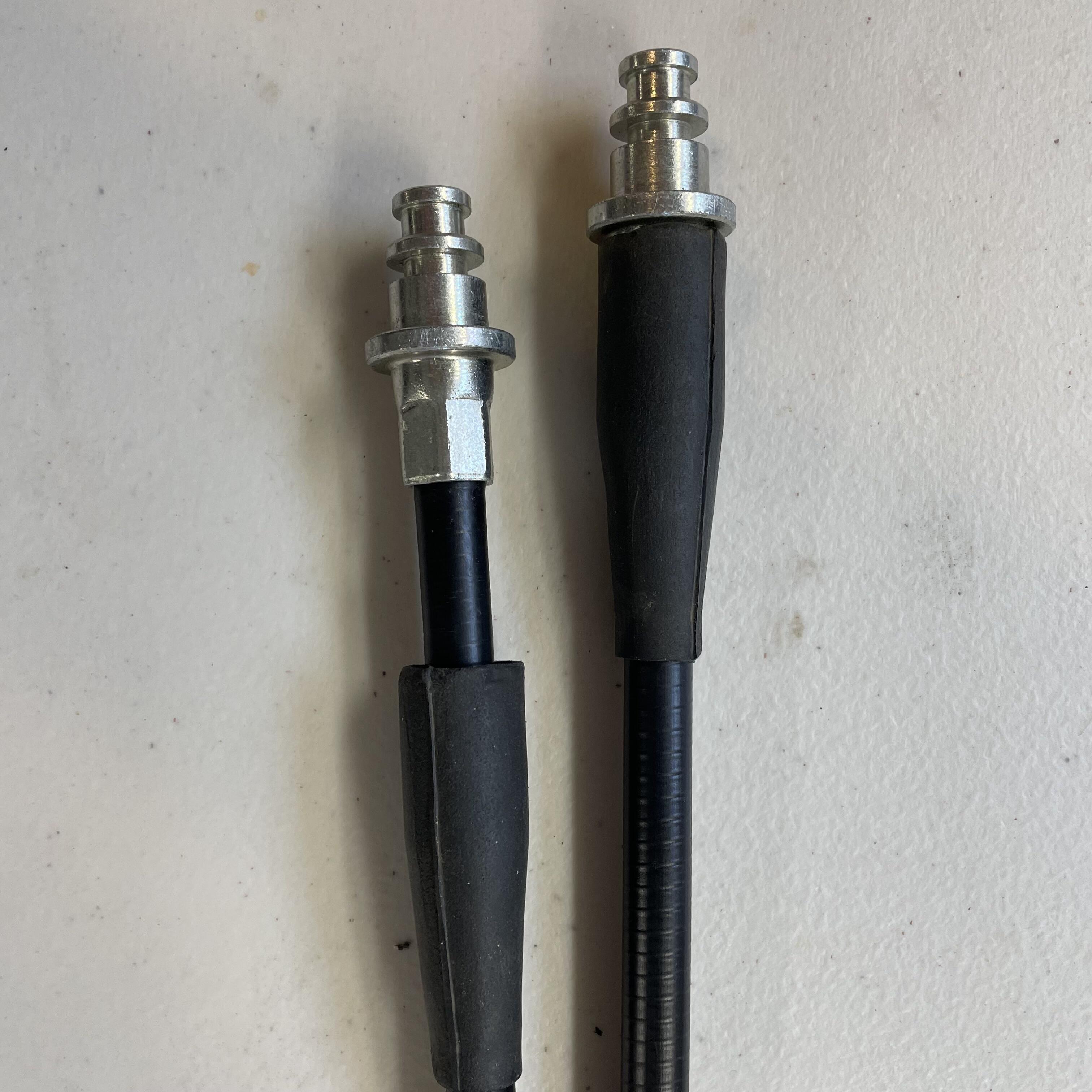
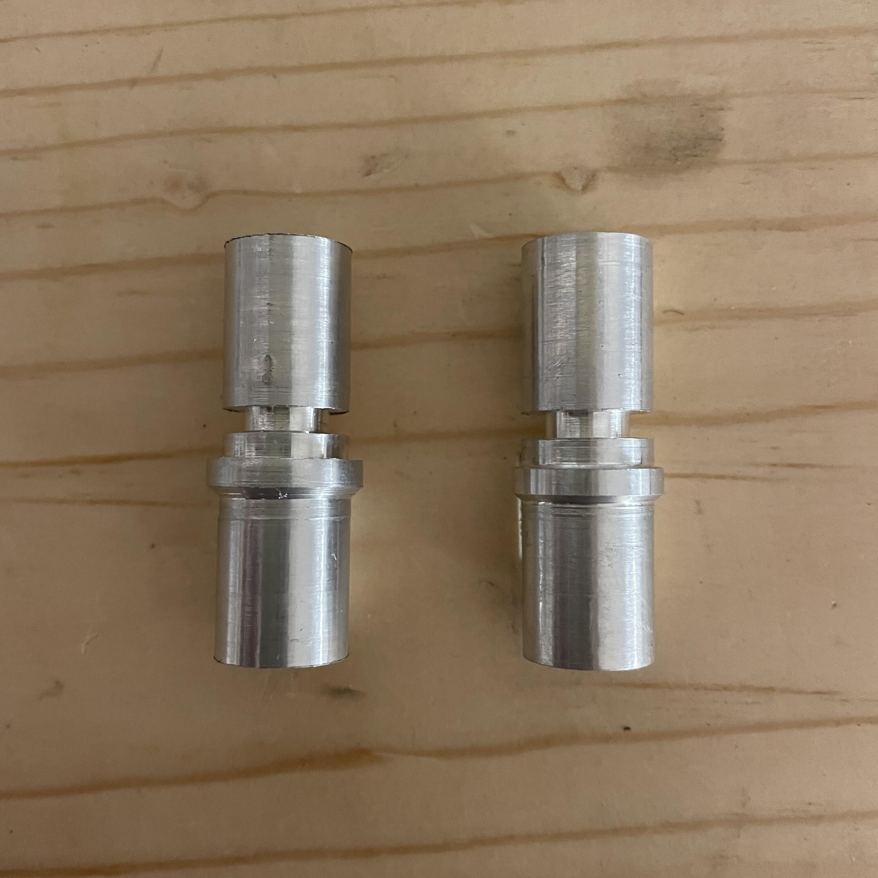
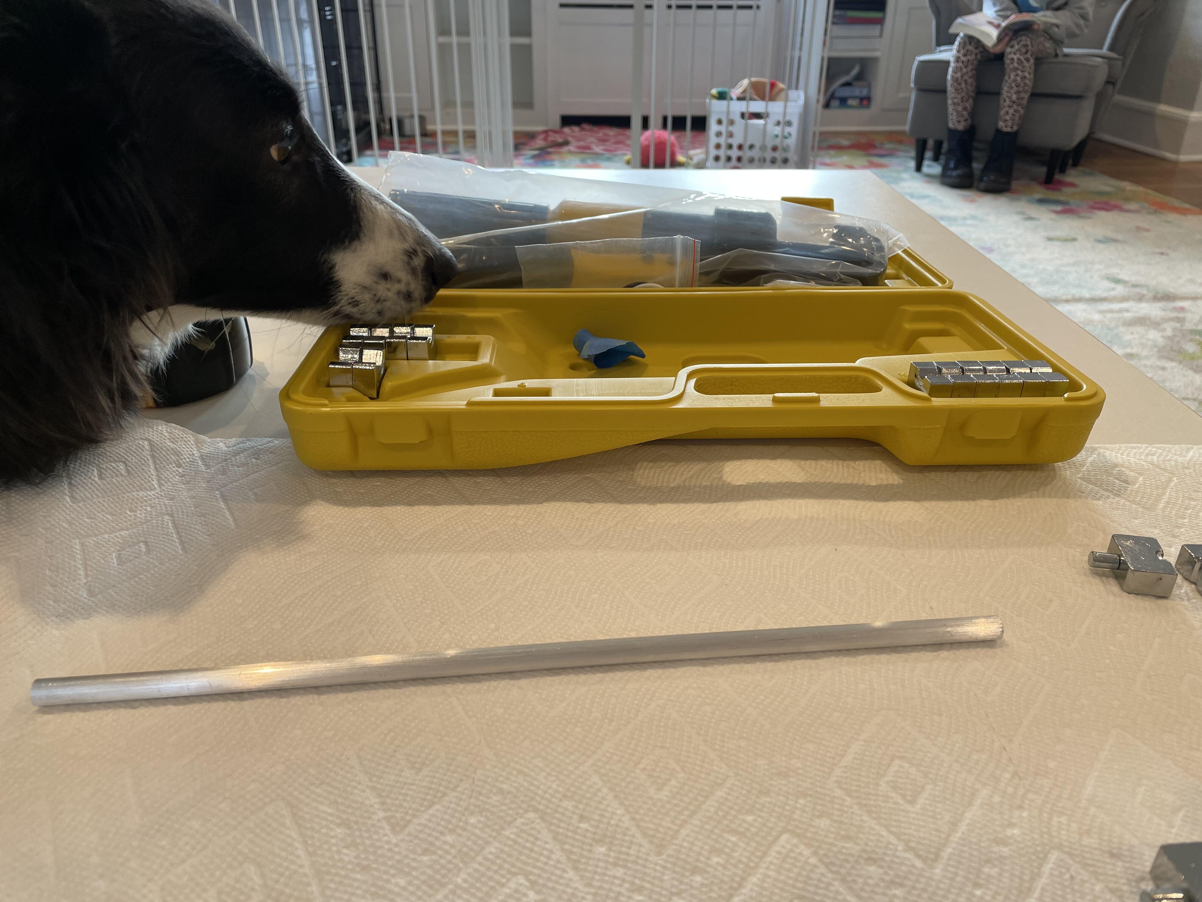
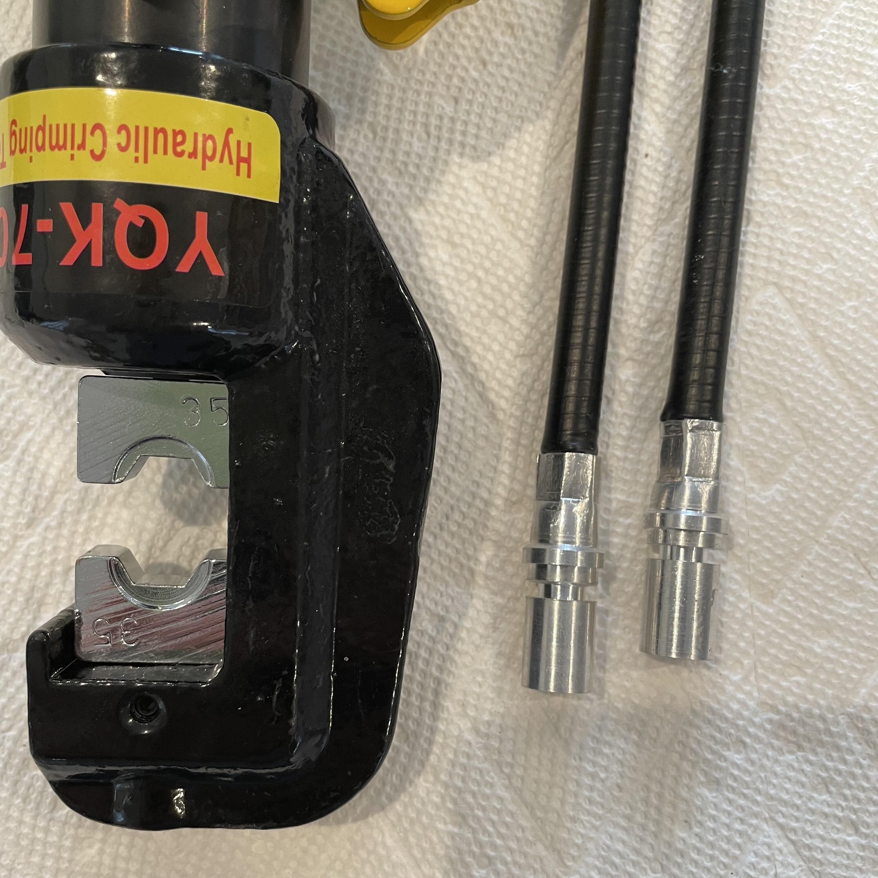
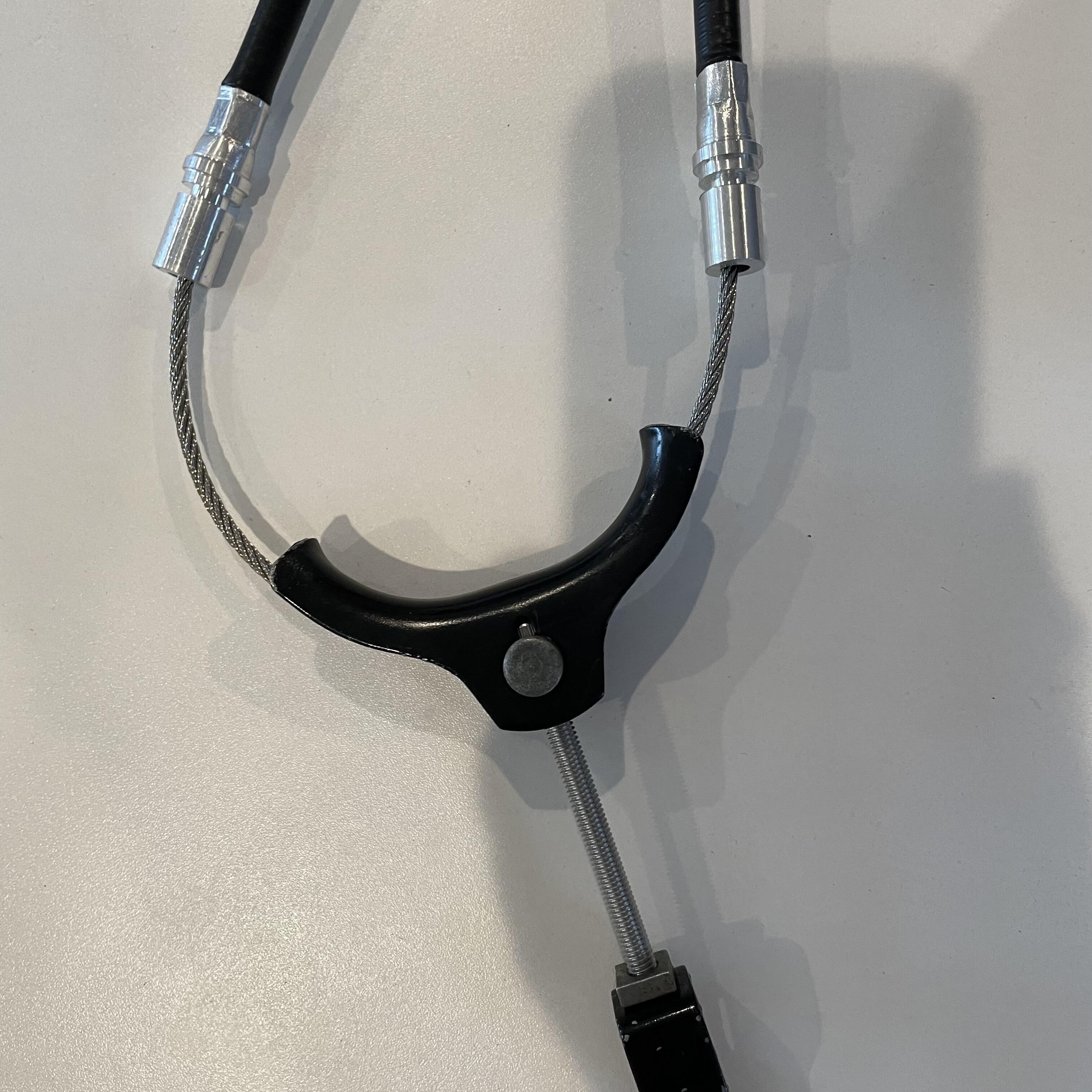
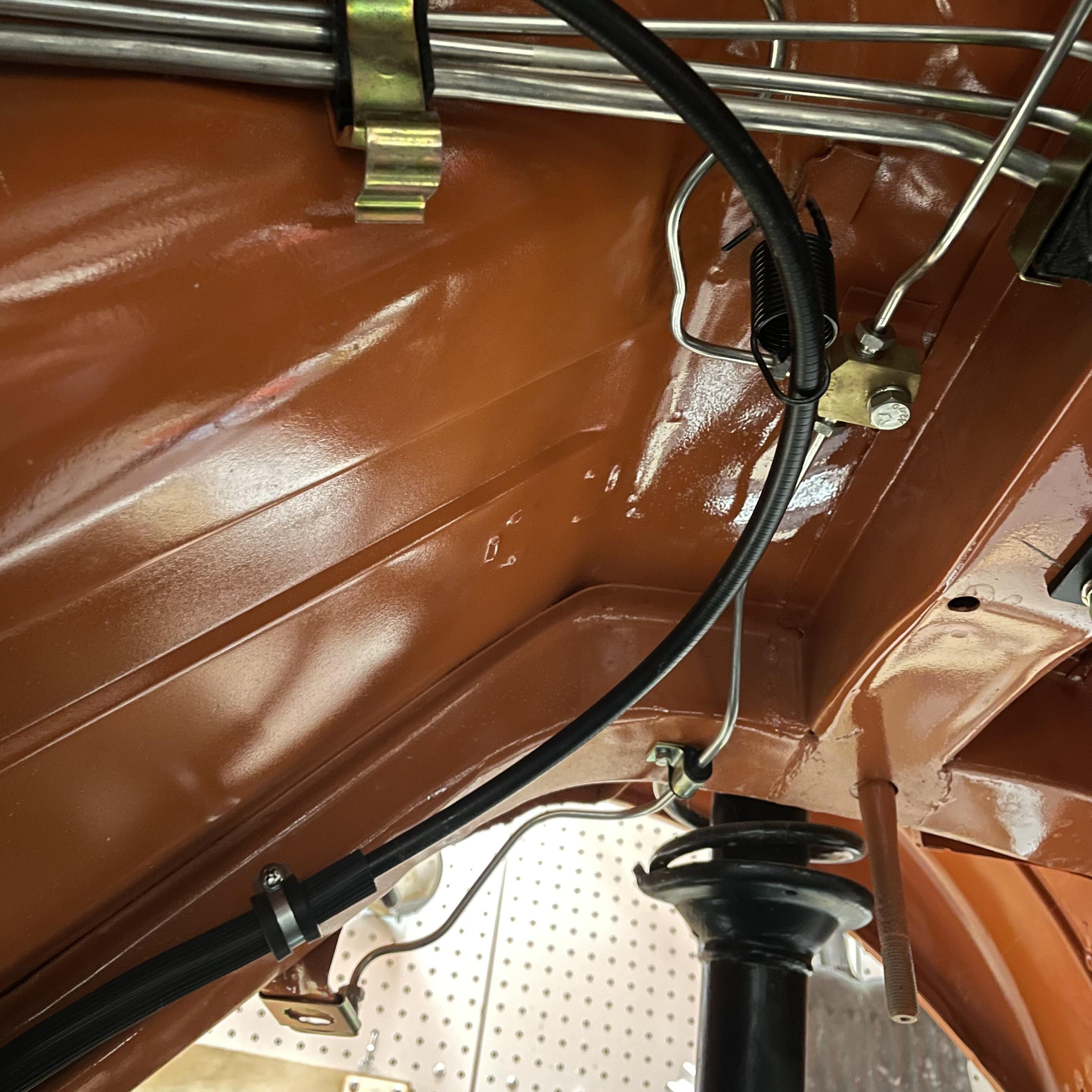
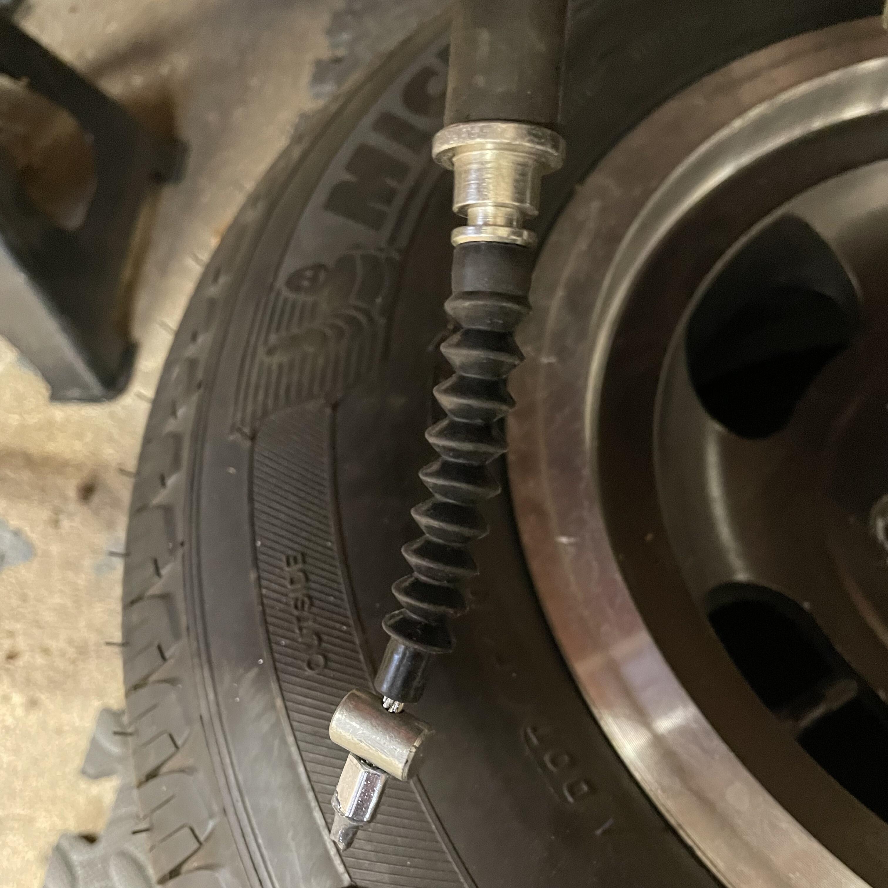
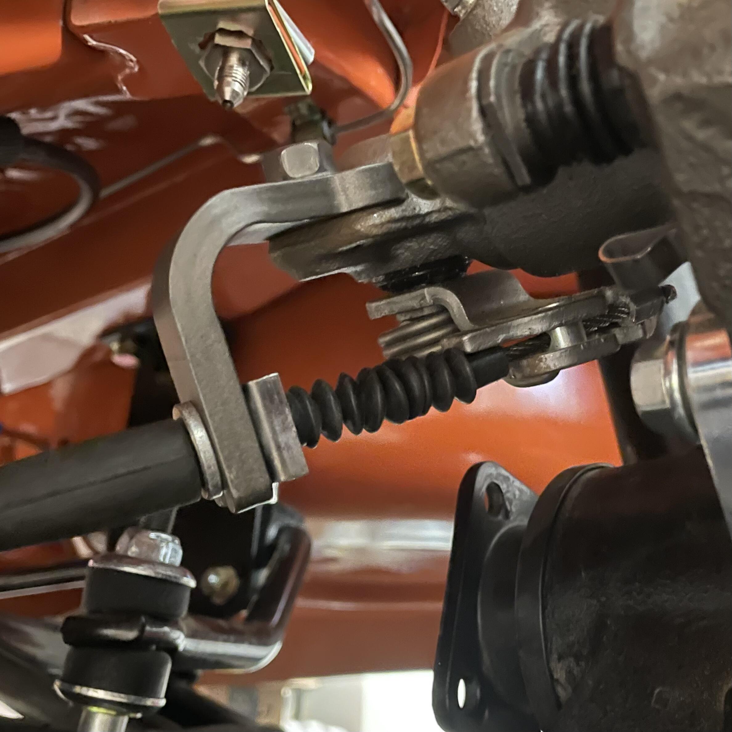
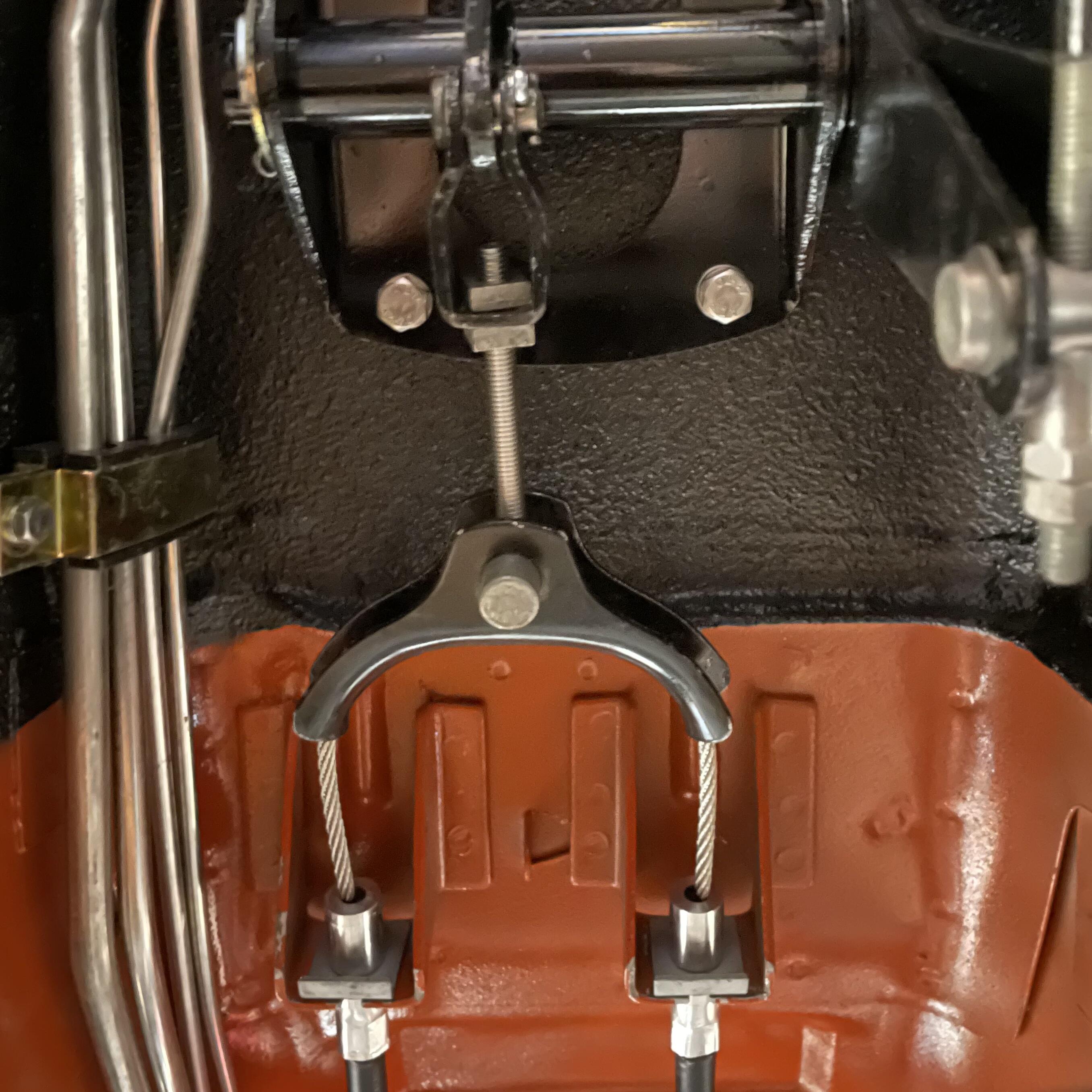
1 pointI just couldn’t live with the gimpy hack that I had to use to get the 240z parking brake cable to connect to my rear Maxima calipers, so I cobbled together my own assembly. This probably could have been done without totally destroying the parking brake cable I bought from Z Car Depot, but I didn’t know that at the time. Here’s a step by step of how I put this together. Someone could probably evolve this and get to a better solution that doesn’t cost as much, doesn’t produce as much waste, and is easier, but this works. If you are using 200 SX calipers I am guessing the process would be largely the same. Supplies needed: 2 x 1984 Nissan Maxima parking brake cable assemblies 1 x 1973 Datsun 240z parking brake cable assembly if you are going to try to get the fittinngs to fit, otherwise you’ll need some 5/8th inch 6061 aluminum rod (or stainless steel if you have a fantastic lathe) + all necessary measurements for the fittings that mount to the bracket on the body of the car 1 x length of 1/8th inch stainless steel cable (I went with 10 feet so I had more than enough to make mistakes) 2 x 1/8th inch cable swage ends 2 x 5/8th inch insulated Adel / cable clamps 2 x Sheet metal screws JB Weld or similar metal epoxy Tools: A swage crimper with swappable hexagonal jaws A measuring tape A micrometer A razor knife Glue Cable cutters A rotary saw A drill + bits Various screwdrivers, pliers, etc. Sequence: Step 0. Either remove your 240Z housing fittings and open them up to be crimped onto the Maxima housing or take measurements from these to have a machinist make you at least 2 sets of fittings. If you repurpose the fittings from the 240Z housing, you may find that heating them with a torch and using punches will work. Mine were ferous but I could not get them soft enough to open without tearing, so I took the machinist route. Step 1. Measure how far the cables for each cable assembly extend beyond the ends of the housings. Disassemble both housings completely. Remove extraneous housing brackets and sheaths from the Maxima housing, taking care to minimize the damage to each piece. Save all parts. Step 2. Find a suitable location for an Adel clamp to mount on either side of the 240Z body. Find a good route around the underside of the car that clears all of your running gear and suspension and allows for gradual curves, preventing kinks and binding. I opted for putting the Adel clamps on the inboard sides of the Bad Dog frame rail extensions I put on the car before the paint was done, as well as using the spring suspenders that the original 240Z housing uses. Take note of where the housing will need to be cut to mount to the under side of the transmission hump in the cable bracket and mark with blue tape or similar. Note: The Maxima housing is slightly larger in diameter than the aftermarket 240Z housing I got from Z Car Depot. Those pieces won’t just slide on, and getting a set that hasn’t been crimped yet was a fruitless endeavor, because the manufacturer didn’t feel like selling them to me. You may be able to go the other way and make the piece that fits into the Maxima caliper and fits onto the 240Z housing, but I found the 240Z housing to be too short to route well without binding and opted for trimming the Maxima housings. Step 3. As stated in Step 0, either reuse or replicate the housing ends of the 240Z cable housing. I destroyed two of mine (there are four on these housings) by trying to open up the crimped ends, which may be possible with the right tools, but I don’t have those so I abandoned this path and opted for having a local machinist replicate the ones I didn’t murder. He made me four of them (2 for failures) out of 6061 aluminum rod in exchange for a 750ml bottle of Uncle Nearest 1856 Premium Aged Whiskey. Stainless steel would be better, but these parts don’t have a ton of force on them in any direction so he and I agreed that aluminum will be just fine. Step 4. Use a rotary cutting wheel to cut the Maxima housings to the length determined during Step 2. For me this came to about 37 inches from the end of the metal part that mounts to the caliper to the cut point. The housings are sprung steel with a rubbery black plastic coating. A hack saw and file might work fine but will take a while and give you a nasty edge because of the coiled design of the tube. I know this because I tried it. Step 5. Relocate the ribbed sheath with the smaller diameter to cover the area where the other sheath was glued to the housing. This is where my finished housing will go through the Adel clamp, and I found this ribbed piece to be a good size to fill the Adel clamp without it squeezing the housing too tightly or leaving it sloppy. Step 6 (optional). Fix rubber pieces in place to aid assembly. I opted to use some flexible glue that gets along with the rubber bits to fix them in place. I wanted to reduce the opportunities for moisture to get into the cable (and this is a nice feature upgrade from the aftermarket 240Z cable I got from Z Car Depot), as well as keep things from sliding around as I test fit everything. Step 7. Reinsert the white nylon tube into the Maxima housing. Trim to be flush with the cut end of the housing. I trimmed both ends to clean it up since it was a bit worn on each end. Step 8. TEST FIT EVERYTHING NOW! Step 9. POINT OF NO RETURN - Assemble the housing pieces and crimp the 240Z housing pieces onto the Maxima cable housing. Be careful to not over crimp the 240Z piece and crush the Maxima piece. CRIMP SLOWLY! The inside of the 240Z piece is going to shrink and may need to be opened up to allow the cable to pass through if it’s squeeze too far. Check tolerances and test fit often. I rushed the first set so all my careful choosing of the best bits was for nothing as my two best ripped and ended up in the trash. Also, don’t crimp too close to the collar. That caused the tears in the first round. Note: A few observations from the machinist about the replica pieces… A. The hole that the cable goes through was hard to get the right size on his 1943 lathe because of his selection of ASE drill bits not being in small enough increments. We opted to ensure enough space for the cable by going a little too big, which allowed the white nylon tube inside the housing to escape as the cable slid back and forth. After the second try I found the crimping shrank the opening enough to keep the white nylon in the housing while allowing the cable to move freely. B. It’s tough to get the channel for the spring clip precise on an old-school lathe. CNC probably could get it closer, but we opted for too tight and filing if necessary. Because these are aluminum and the spring clips are steel, a little persuasion with a brass hammer did the job. C. The reason we made 4 and not 2 is so we could test all tolerances and choose the combination of fine tuning challenges. Since these are all hand made there were differences, so I used hand tools on the fittings and the bracket to make them fit. Step 10. Test fit again. Step 11. Put the rubber boots onto the ends of the Maxima housing. Step 12. Crimp a swage onto the end of the steel cable. Put a cylindrical bead from the Maxima on the cable, followed by one of the Maxima housings with a 240z end. Put the couple for the hand brake on, then the other Maxima housing with 240z end (flipped the opposite direction), another bead and a swage end. DO NOT CRIMP THE SECOND SWAGE END YET! BONUS PICTURE OF DOG INTERRUPTING PROCESS. Step 13. Test fit the entire assembly. Make sure the screw that connects the U-bracket to the handbrake lever is fully extended to ensure the maximum available adjustment length, but lease a few threads peaking past the nut for a smidgin of safety. Note: I replaced the OEM screw with a 70mm stainless M6 1.0 pitch hex socket cap head bolt. It fits into the assembly well. The old one was bent and this one has threads down the entire length, giving me much more room to adjust it. Any cable will stretch over time so you want something like this to maximize adjustability. Step 14. Position the bead and swage end you didn’t crimp inside the caliper lever, pull the cable taught, and mark the position of the swage end on the cable with a piece of blue tape. Step 15. Remove the assembly on the side that you just marked from the caliper and crimp the swage end where it should be. Cut the excess cable off. Note: I put a bit of JB Weld over the frayed end of the cable where I cut it, bonding it to the crimped swage end on each side of the car. This will keep moisture out and gives me just a little more insurance that it will stay on, because Garage Build. Step 16. Reassemble, tighten the bolt that joins the cable to the hand brake, and test the system. Edit: The slack you see above between the swage end and the bead disappeared once I tightened up the bolt in the u-bracket. Edit: I think I might end up putting zip ties or something on the boots that cover the black Maxima housing. The glue I used isn’t holding. I might also have used a nylon coated cable if I was doing the entire thing over again. The reason I didn’t is that I didn’t trust the swage end to stay on with that nylon creating a failure point. If it disintegrates you end up with a loose crimp, and since this was done with hand tools I just didn’t feel confident about that.


 1 point
 -
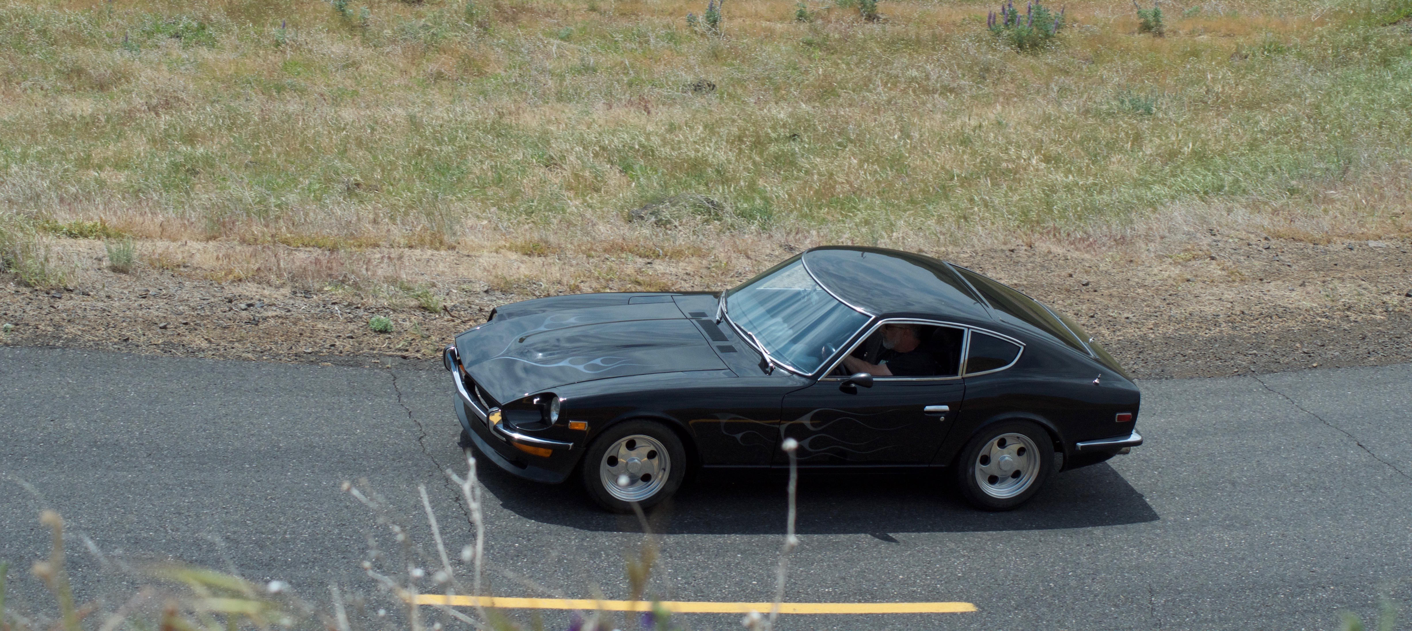
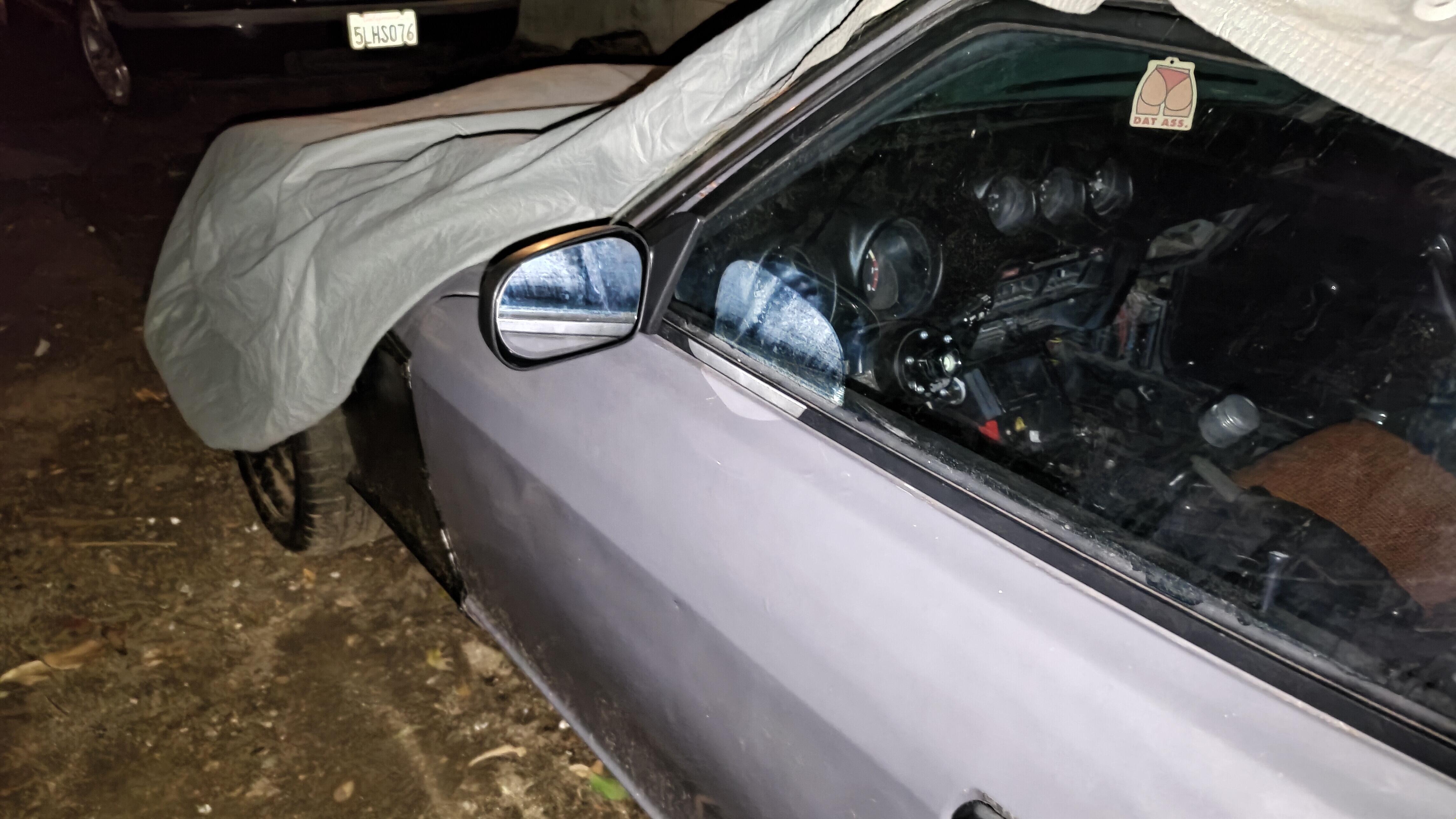
1 point1 pointSaw this today. Our Zs are easy to steal…unless you try to steal mine which currently has no dashboard or seats 😂. I suspect this car could pop up somewhere for sale.
 0 points


Important Information
By using this site, you agree to our Privacy Policy and Guidelines. We have placed cookies on your device to help make this website better. You can adjust your cookie settings, otherwise we'll assume you're okay to continue.