Leaderboard
-

wheee!
Free Member3Points4,607Posts -

siteunseen
Free Member1Points15,115Posts -
zKars
 Subscriber
 1Points3,769Posts
 -
beermanpete
Free Member1Points772Posts


Popular Content
Showing content with the highest reputation on 01/28/2016 in all areas
-
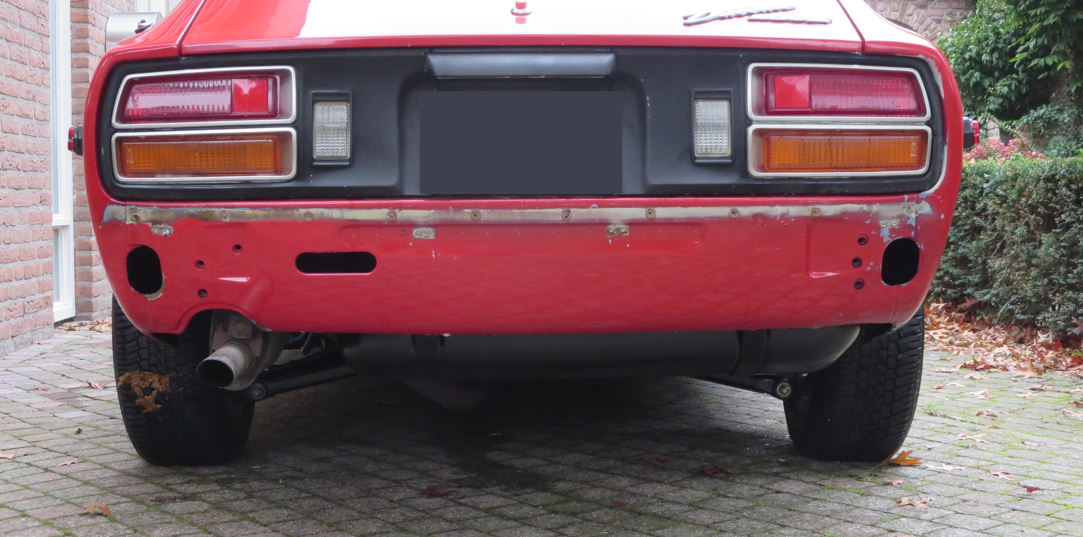
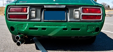
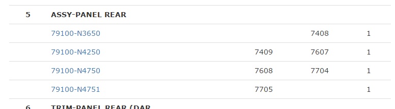
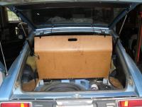
1 pointThere has been a lot of disscussion about the series 1, 2 and 3 240Z. The 280Z has similar changes and at first glance August 77 seems to be the change over point. I often see threads getting side tracked about these differences and when they occured. A lot of good inforamtion, but its scattered over a lot of different threads and difficult to find again. This might be a goed way to collect information about these differences and share with other members. To start: Rear Panel Im making brackets for my 240Z bumper mod. The first thing I noticed was the bolt pattern for the bumper brackets. According to the parts fiche they changed around 5/77. Before 5/77 the 2 bolts were in a diagonal pattern, left low and right high. The patterns were the same on the left and right side. After 5/77 the right side bracket changed to two in a vertical line. Why they changed this is a mystery to me. It may be something to do with the 260Z outside the US. They were not used to mount the 280Z bumper. The second difference is the four slots (two long and two small) changed to one long on the left side. I have some photo's of the differences. The green car is a 76 and my red 280Z is a 5/77 (VIN: 403100). Mine is probably one of the first with this later version. This post has been promoted to an article

 1 point
 -
1 pointExcellent idea Chas! Mine is definitely like the top photo, 1976 I wonder what the thin indent (offset) was for? It has screw mounting points too... My plan is to fill it in during the bodywork.1 point
-
1 pointI can't tell much from your photos. You need a factory service manual with the wiring schematic so you can trace the wires by color through the car as you troubleshoot the problem. I think you can get a free copy from xenonzcars.com. Since you have no power at the turn signal switch it seems like the problem lies elsewhere. Does the car run? Does anything that is controlled by the ignition switch work (i.e. radio, heater, wipers)? Power for the turn signals runs from the ignition switch to the fuse box, then to the hazard switch, then to the flasher, then to the turn signal switch. Start by checking for power at the 20 amp fuse for the turn signals. It should be hot when the key is in the on position. Check the fuse itself and (assuming it is goog) clean it and the clips it snaps into. Next, check for power at the two green wires on the hazard switch. One is the feed from the fuse box, the other goes to the flasher. Next check for power at the flasher (the one with a green wire and a white wire, the other flasher is for the hazards). Next, check for power on the white wire at the turn signal switch. The first place without power tells you the component upstream, or a connection in-line from it is the problem.1 point
-
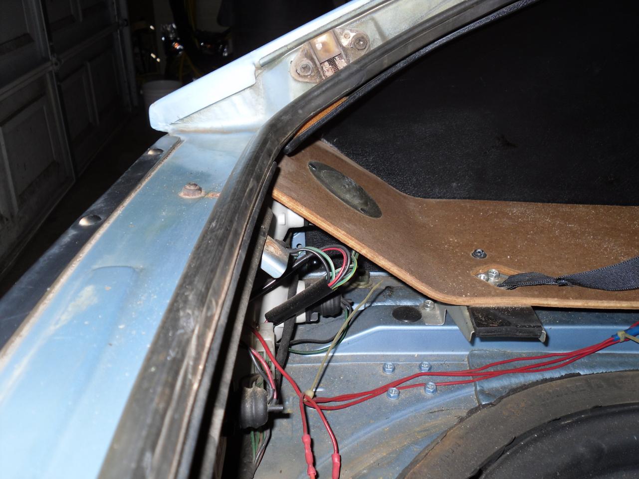
09/76 build date, accordion front bumper ends, N42 spray bar on a drilled cam N47 cylinder head, collapsed spare with air bottle. it's a mix of parts for sure but they are all original, for sure. I think they were using up all the stuff from '76 when mine was built, my Dad calls it a hermaphrodite car, but he's on some heavy meds. those red wires you see are from an alarm system. You can see the spacers they put in, towards the front of the spare. The 75 and 76 had less space with the raised deck, 77 and 78 were lower with the space saving spare, more room for kids or golf clubs etc. I would think the 78s didn't have those spacers, allowing the lower deck height. Just a guess though, when I had a 78 it was in the late 80's and I don't remember much from 85 through 1999 or so.
 1 point
 -
I sold it right here in the classifieds! This is the For Sale section isn't it? I quite sure mine is the early switch. The picture you showed is of a later switch. The key to telling them apart is the head light switch wires. On the late 71 and later, the main HL on-off switch has a White/Red power wire from the battery, and a red one exiting the switch. This goes to the fuse box to energize the headlights. On 280's these WR and R wires get quite thick, I think 10 gauge and the bullet connectors get bigger too. Trying to make things better. Yet they keep the same switch... Sheesh... On the early switch, they switched the ground side of the circuit leading to the dimmer to turn the Headlights on, and the wire colors and routing of the HL switch wires are different. They use black wires bringing "ground" from the chassis, through the switch, to a red wire, that jumpers over to the center of the dimmer switch. The head lights common terminals are hard wired directly to the HL fuses to energize them. This was an early design, after this they all use the "switch on the hot side to the fuses" approach with the WR in and R out until 78. At least in North America. Also 280 switches are easy to tell apart from 240's. The HL/Wiper stalk angles up 15 deg or so, while all the 240 stalks are horizontal ( and hidden very well by the steering wheel spokes, hence the change in 74)1 point
-
1 pointI'm way passed that point, bartsscooterservice! I've already coated the items in sharkhide, so that's what they'll stay like. Not overly glossy, just the right amount of sheen. As for the clutch situation. I managed to install the new crank seal, pilot bushing, and reinstall the backing plate (scatter shield), dowel, and put the trans on with the clutch bits and transmission parts all squared up. The only issue I seem to have is that the throwout bearing collar that I do have is neither of the 4 used on various S30's... (I have a picture below). it WAS the one that came out of the vehicle because the wear pattern on the throwout bearing that I removed from it matched the one on the pressure plate. So I think it should be compatible. It just feels like there is a little bit of play in the fork before it makes contact with the pressure plate diaphragm. Time will tell, I guess. It's not the worst thing that could happen if I need to replace it. At this point I need to move forward with the rest of the resto so I am choosing to try this one and see how it goes. In fact, I'll be putting the motor in today, so it was a necessary step to just get it on there and hope that it operates as it did before the car was taken apart. backing plate, new seal, and new bearing installed. I drove the seal in just a hair further than the one that was there, as i felt as though it was riding on a portion of the crank that looks to have been running a seal for 40 years, so the trick there is to drive it in about 1mm further (well within limits) so that the portion of the crank it seals on is of original size. Here's the OEM pressure plate, with some marks I made while removing and reinstalling the balancing weights. the top marks indicate the group, the single dots indicate whether it was completed or not. Nothing special, just my method of doing things. 30210 imprint, looks somewhat like 3G21D, but 30210 are the first 5 numbers of the clutch pressure plate part numbers: AMPCO stamping (upside down) - an original driveline component supplier for the early models. Extremely faint (probably due to the sharkhide diluting some of the ink stamping), It is (or was) a circle that reads P in the 12 oclock position, A in the 6 oclock position, and REBUILT across the middle. The R, BUI, and T were distinctly visible, so I played wheel of fortune on the other letters. Here's a shot of Group 2 of the balance weights. This group had a single rivet with no weights attached and no sign of weights or markings from corrosion around it, so I suspect that the weight of the rivet was all that was needed. Is this rivet the same weight as the one installed from the factory? probably not, but one came out- so one goes back in. Rivet on Rivet contact. You can't see it clearly from here, but the edge of the rivet on the pressure plate contacts the disc sold to me from the dealer (the STANZA disc from valeo). A "Z" stamping on the inside of the pressure plate under the spring diaphragm (COOL!), and would it not be for the rivet/rivet contact, the captive tabs for the hub springs would hit the 3 flat portions of the cast pressure plate friction surface. New Stanza disc: Nearly Identical to the ATSUGI disc that came out of the car in dimensions, but with minor differences around the springs: Tons of clearance from both: Stamping ID's on the disc: ATSUGI, 30100 (first 5 digits of the part number group), and F225DC (225mm) Good idea of the taller hub splined section: Shorter hub splines on the ASCO replacement disc. Still plenty of engagement. Top side fastener comparison (looks very alike!) Bottom side (also quite alike!): Disc installed using an old tool I had from my Z31 300zx disc kit. Nissan uses the same 24T spline for just about every transmission assembly (which I think is shared by subaru), so it worked well. flywheel installed, torqued to 100ft.lbs with a smidgen of blue loctite and some hash marks for future reference. I generally don't draw a line across the entire bolt head, but I don't know what I was thinking at this time. Doesn't matter. It's not important, really. Now I know this is getting reallllly nitpicky, but i put some sharkhide on all the areas of the pressure plate that does not come in contact with the friction pads. I hate rust. I try to hold it back for as long as I can. If the very thin coat of sharkhide will prevent that from happening, then it will go on. For this type of stuff, I use sharkhide that i've dipped into some various brushes into, so while the sharkhide itself is a tad less "transparent" than fresh fluid, it does the job and won't be seen anyways. Don't have pics of the Pressure plate installed, but here is one with the throwout bearing collar I had, with measurements. (visually different in outer shape than the 240 one... I think it's from a 240sx. But it did come out of the car because the bearings matched the pressure plate wear. Time will tell, I guess! As for removing the pilot bushing. I've had mixed success various ways, and some are not suitable for certain engines. I'll explain below: Removing with Hydraulic / Grease method works but it's a little messy and requires a amount of force to generate pressure (bad for thrust bearings). Removing with Wet Paper / Bread method works but also requires a considerable amount of force to generate pressure (bad for thrust bearings). Using those two methods are suitable for a number of vehicles, or in a pinch- but also not suitable for those which have plugs taped into the back of the crank input shaft hole. Some are not just drilled, some are sealed. Popping that press fit plug seal out is bad news for a lot of reasons that I don't need to explain. Using various pullers is sometimes convenient, but there are some that don't like Nissan bushings being that they're extremely thin. I've rented a couple of the tools from auto parts stores, and found that they work with modification- which I will not do on a rented part because I'm renting it so I don't have to own it. There are ones for motorcycles that work exceptionally well for small bearings and bushings, but again- money. time. ordering. waiting. no way!!! Cutting it is also an option. You make a small slot on one side of the bushing with a fine tooth hacksaw blade. It just takes a long time. I don't enjoy it. And I only had a jig-saw blade with me that was a little too course. I got through a considerable amount of bushing material before realizing I couldn't cut the back of it with the coarseness of the jigsaw blade TPI. So I figured I might as well mimic a puller, and to date- this is the best trick I've found for these thin nissan bushings in particular, and literally took about 4 or 5 minutes to concoct and achieve success: Shove a bolt head in behind the bushing. put a large wrench over the hole, shove a pick or an allen key next to the head so it doesn't pop out or spin, and then just stack washers on the bolt threads, and tighten them down with a wrench/ratchet. The bushing just slides right out. And believe me, the slice down the middle had nothing to do with it. It was in there. I couldn't even spin the bushing with a couple of chisel hits even after all that cutting (as noted by the small deformation at the front edge of the cut). The back of the bushing was still much too intact to relieve any tension on the bushing to crank interference fit, so I'd say my new found method did the trick quite well. Sooooo that's my update from yesterday. More today hopefully.1 point
-
1 pointMore progress albeit slow. Door frames are done along with inner cowling and windshield moulding. Taillight area still to do along with the interior. Feels like I am getting closer to being done with the media blasting. At least of the frame. I will blast a few larger parts while I have the tent setup. The new tranny for one and the front crossmember come to mind. Oh well. I'm in no rush I guess!1 point
-
1 pointFinished the engine bay last night! Still lots to go but a productive evening anyways! Wheel housings look better too. Both pictures are from before I started the night and the room filled with dust... It will indeed take a while to purge the car of media after I'm done...1 point