Leaderboard


Popular Content
Showing content with the highest reputation on 01/09/2016 in Posts
-
2 pointsIn case you haven't already seen it - Motorman's beautiful 240Z is featured in a story on the Hagerty Web Site. https://www.hagerty.com/yourstories/2015/11/29/all-in-the-family-unrestored-240z201511291123352 points
-
Hey gang, just ordered and now installed a complete set of Precision weatherstrip on a 71 S30 purchased from MSA (the weatherstrip, not the car, sorry...) The door weatherstrip was the big surprise. They seem to have gotten it right finally, the doors close exactly the same as they did with the old stock weatherstrip. No slam, no protruding doors, no drama. Just a decent fit. The bulb size is equivalent to the Kia weather strip, in fact, the precision strip is a U, not a closed circle like the Kia strip, so is more flexible, and more like the stock cross section. Might have to go back to ordering this stuff instead of the KIA part again.1 point
-
Love this song.. and well she's talks about " Datsuns " We are drinking beer at noon on Tuesday In a bar that faces a giant car wash The good people of the world are washing their cars On their lunch break, hosing and scrubbing As best they can in skirts in suits They drive their shiny Datsuns and Buicks Back to the phone company, the record store too Well, they're nothing like Billy and me, cause1 point
-
1 point
-
Very cool. Thanks, guys. An update from my end: The labelling for Fig. EC-20 is, indeed, reversed re Items 7 & 8. The 'case cover' is simply threaded onto the main casing, so it's easy to get off (big hex-nut fitting). After the cover is off, though, there's a brass cap (from which a central shaft with the adjusting nut protrudes) that looks like it's a press-fit into the main casing... so I'm probably never going to get to inspect the innards without destroying something. I've got my thermostat soaking in CLR now. There was a lot of 'action' right off the bat, so my suspicion about mineral build-up might be correct. We'll have to wait to see, though, whether it frees up the workings. Interesting that the designers decided to add an adjustment facility for such a simple device. That may explain, too, why there's a threaded cover rather than just making the device completely sealed. Maybe they knew something we don't ! Don't know if anyone else spotted this, but the intended flow direction for the coolant is the reverse of what I would have expected. According to the FSM diagram (unless this is another labeling error), when the T-valve is open, the coolant is flowing out of the rear bypass tube, through the T-valve, then into the manifolds, and finally exiting into the main thermostat casing at the front of the engine. I always thought the flow direction was the opposite (i.e. from front to back, and then around the rear of the engine into the Y-fitting). I guess I'll have to go back and look at those coolant flow diagrams that someone came up with in the midst of that long debate over whether or not it's safe to bypass the cabin heat coolant circuit. I'll report back tomorrow on whether or not the CLR soak worked.1 point
-
1 pointYep, here on the west they also use sand. They've been talking about spray chemicals but the environmentalists are all over their asses about it. I agree that salt makes the ice older, but it does melt. The thing I don't understand is why they continue using something that literally acts like acid on everything it touches. Have you ever seen how salt eats away at concrete ? We use it on sidewalks here and I can literally see pits and cracks caused by the stuff. I wonder if there has ever been a class action lawsuit against the highway dept from car owners. It's horrible on cars.1 point
-
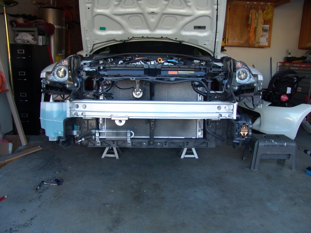
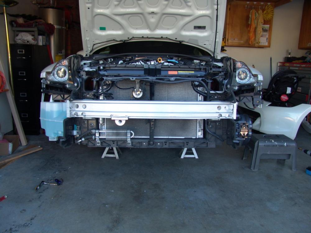
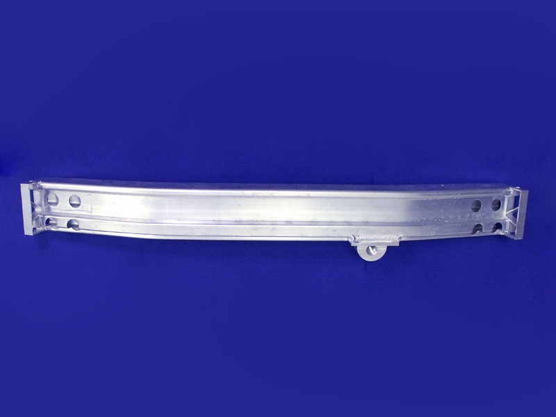
That is why I was thinking a cross brace between the two existing bumper shock mount points. From there, you would have the right height to mount the front bumper and add the tow hook thread point. Wouldn't need to as heavy duty as the examples below if it was steel versus aluminum. The crash bar in my 370Z performs this same function. Might work!
 1 point
 -
1 pointAnd I suppose you don't see a baby holding it's fathers thumb in this one?1 point
-
1 pointGet the R's. Period. As for the engine hesitating at 16 to 1 at Cruise? All engines are different ( just like wives ) There's a golden rule with engines...( also like wives ). Give the engine what it wants to be happy. If it wants more fuel.. give it more. If it's happy on less fuel... give it less. Same with timing. And the only way to achieve this is to try different combinations. For maximum Fuel economy at cruise, give the engine the least amount of fuel that it''s " Happy " with. Try 15.7 and see if the hesitation goes away. Or 15.5 or maybe 15.2. Eventually you'll hit the " sweet " spot and that's what you want. A Load Cell Chassis Dyno is the best way... but you can sort things on the Road. Just be careful and obey the Law. Best to have a passenger to monitor things while you concentrate on driving. You can do a lot with a WB AFR meter and a Vacuum gauge. But they are only instruments. You have to determine if the engine is responding properly. Now.... once you have spent years developing the skills necessary to to tell if an engine is contented and running efficiently... try that with women. Good luck with that!!!1 point
-
Found some old CZC.com threads on the steel Porsche-style, and actual Porsche factory, synchro topic. Haven't figured out if it's just the synchro/baulk ring or if you need the gear/cone that goes with it too. Steel and brass might not be interchangeable. It looks, though, that the gear ratios might tell if you have a Competition transmission. The ratios can be pretty tight 1st to 5th. Might not even be suitable for the way you plan to drive. Here's one example, not sure if they're all like this. 2.906 / 1.902 / 1.308 / 1.0 / 0.864. 2.906 would need something like a 3.9 diff, which would make the .864 5th a 3.37 overall. Compared to a .864 with a 3.54...3.06. Just playing around in your thread. Good luck.1 point
-
They're probably following this thread and don't want to open a new can of worms. He hasn't fixed the most basic problems yet. Getting in to the carbs would just add to the chaos.1 point
-
1 pointAny suggestions on spark plug wires or is there an ideal size/type for strokers ?1 point