
Blitzed
Community Member
-
Joined
-
Last visited
Everything posted by Blitzed
-
View Advert 73 240Z Seatbelt Receivers Left and Right Looking for a set, left and right seatbelt receivers with the hard plastic cover. See image. Advertiser Blitzed Date 08/12/2021 Price Category Parts Wanted Year 1973 Model 240Z
-
Bless you friend, a solution. Thank you for the post and help.
-
Hi w3wikes, All good data. I've located the connector at the console, no issues there. Sorry, not familiar with the term "jumpering" . How do I jumper the console connector to activate the circuit? my last instructions were to meter the fuse and connector and determined which side of the fuse had the juice. left side of the fuse, no juice. Right side juice, so the connector is not part of an existing circuit. Never received a you're screwed, so just assume so. From another post about relay's on the passenger kick panel , assumed I'm missing components to complete the circuit. Are you suggestion another path to power the connector? Thanks for the info.
-
Hi SteveJ, Yes fuse was pulled but operator error forgot to reinstall the battery ground. Once the battery ground was installed, close to zero (.1,.2) on the left side for the black and white and larger reading on the right side. Green is dead both sides, yes un-terminated wire at the fuel tank connection.
-
SteveJ, Hope all is well. With all reinstalled and connected. Key in the off position. The green wire is dead from both side of the fuse holder. The black / white has continuity from both side of the holder. Right side registers a larger number .19 on the meter left side lower .12 ???????
-
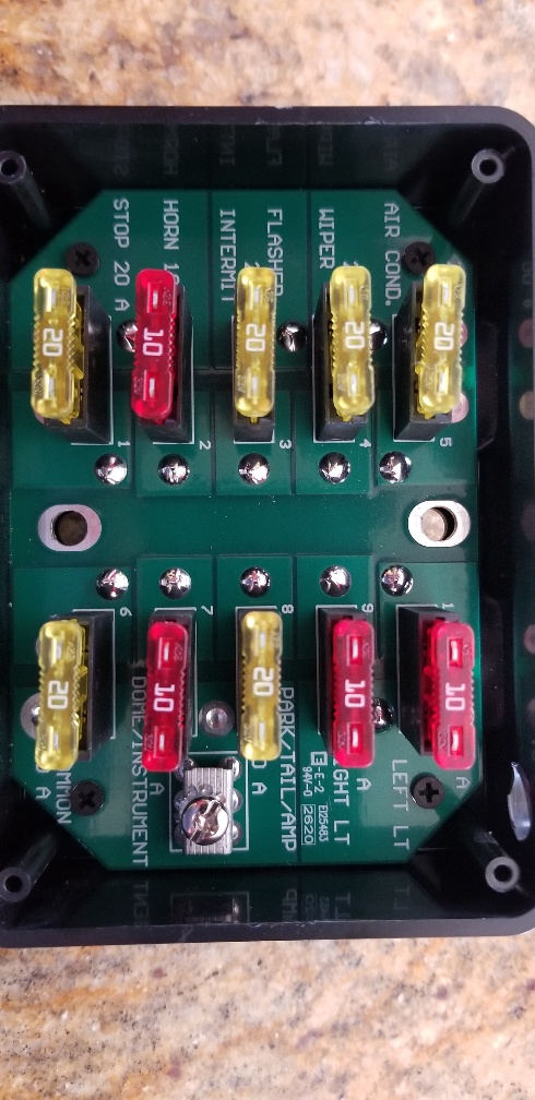
Hi Patcon, Will do as soon as the fuse box is reinstalled in the car. As with most hunt for the unicorn it requires access to the harness. Assume this fuse box will carrier the same fuse location to check for continuity and same side of the fuse?
-
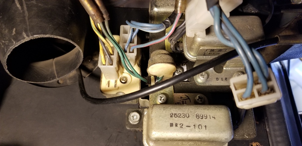
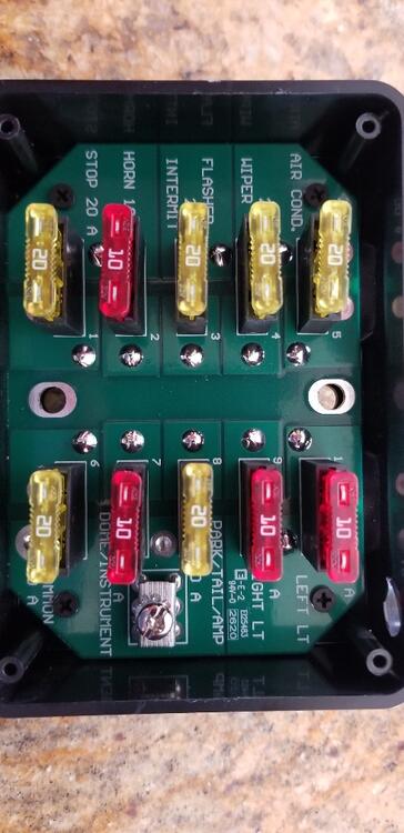
Hi All, See relay pic. Only four relays on the right side kick. Car is documented as 73. Had the square rear sway bar mounts on the sub (no bar), so would assume late production. Thank you,
-
Hi cgsheen1, Thank you for the response. So in the simplest answer yes or no. On a non factory fuel pump 240z. Did Nissan just run the wires and not complete the connection to the ignition? Lose connector at the console. If not complete, did they provide another factory connector at the console to plug into or do I need to run additional wires to the ignition to complete the circuit and power the pump? have a FSM but wiring diagrams are a mystery to me. Thanks for the help and safety advise. Will purchase the switch.
-
Hello Zed Head, Thanks for the info but did not satisfy the question. Found the info on the second connector, fog lights. Will not put them together :) So anyone who has added /installed a fuel pump to a 240 (not previously installed), please respond. Found the connecter and proper wires at the console. The connector is not plugged into another terminal. Where does it connect? No power with key in start position as it is a lose connection. Thanks you
-
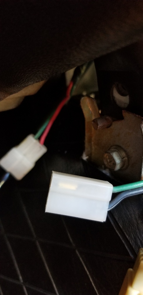
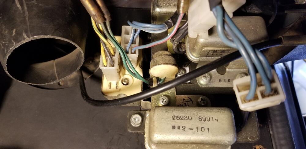
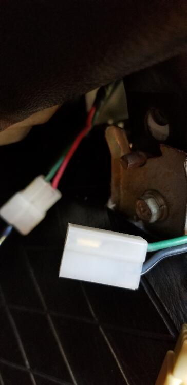
Hi All, Searched "Help Me" but came up short the specific answer. 73 240Z non fuel pump version. I'm installing a fuel pump and stumped on the factory wiring config at console. Black and Green wires at the tank - Wires are there, all good Black/ white and green under the console - Found them, see pic The Black / white and green connector has never been connected to anything in the harness. Looks brand new. The only other connector not connected (same style 2 pin connector ) has a black /yellow and red wire (background of pic) and appear to loop to the fuse box. Could just put them together and wait for smoke and flames :) Need a confirmation on this connection or another location. Thank you.
-
-
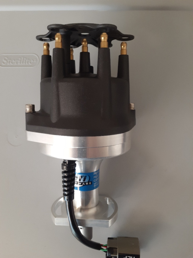
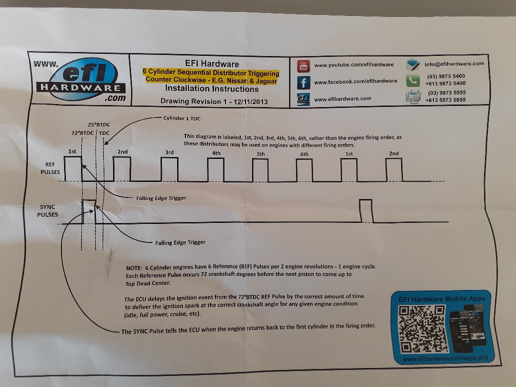
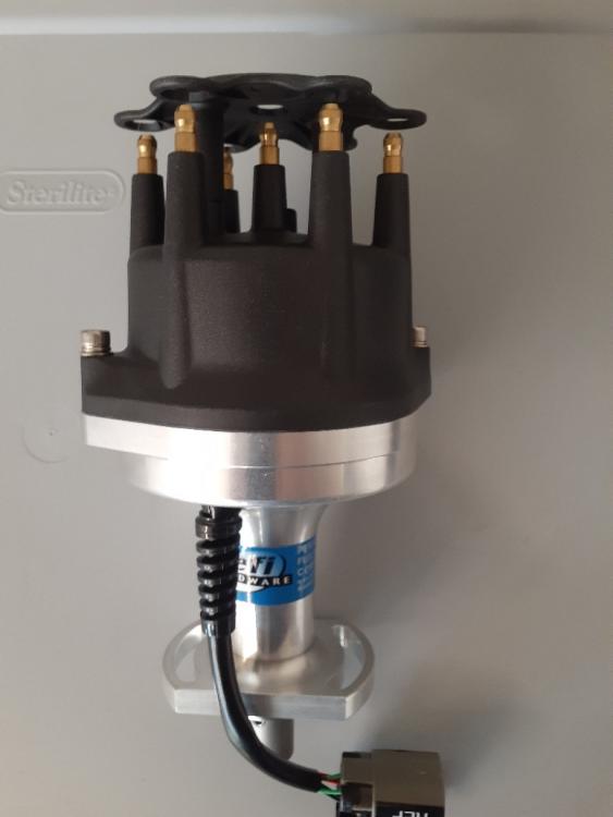
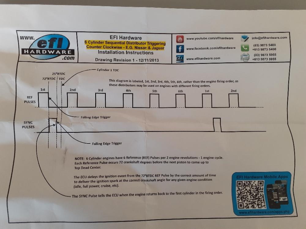
Thanks for the info. The config attempting to set-up is not unusual but not the choice of most. The hall effect distributor purchased (new in the market) will allow the set-up to start with a single H.E.I coil, sequential fire distributor, easier to convert to EFI but for some not the most efficient (this is not a race car, drive). See distributor pic and hall effect signal provided by the unit. The nice option to this distributor is the ability to remove the distributor cap, install a distributor cover and run a distributor less coil pack or COP set-up in the future. First ECU install and EFI conversion so the leaning curve will be a single coil and sequential fire. Rotor phasing is complete (not test) dwell will be a programing function through the ECU. Apologize my initial post was about wiring in-line with stock harness as with new products /conversion you end up going down different paths.
-
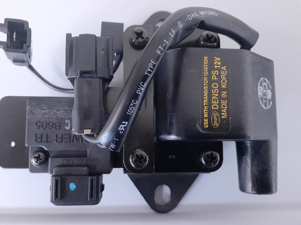
Hi All, Correct, ignition module required. The HEI coil pic in this post has a 3 pin igniter/ ING module (blue dot on top) integrated. All of this is straight forward, wires coming from the ECU and neg from coil. My concern is eliminating a connection from the existing harness at the coil and ballast resistor. Thanks,
-
Hi SteveJ, It came with a wiring diagram for the new components. The more I talk this through or over thinking it. There are really only two connections from the stock harness. ECU to the IGN switched 12v (key) and connect the black/white on the positive side of the old coil to the positive wire on the HEI coil, should be good. There are no points so the negative (black wire on old coil) side of the coil is eliminated. The ECU will ground the igniter and coil. All other connection remain the same. New new coil requires an igniter wired through the ECU and connects to coil, the new distributor wires directly through the ECU (no connection to the coil other than the coil plug wire to distributor cap). All other sensor have assigned wires through the ECU. Will just keep the stock ballast resistor and connections in place. Not sure if they're needed or function but it can't hurt? I guess :)
-
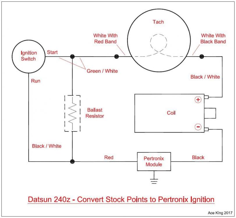
Thanks Zed Head and Steve J, Still a little confused but getting closer to really confused, how I like it. Ign switch: Based on the response I should spice into (and not remove) the switched 12v ign wire from the Z harness. Too much going on down the path. The Haltech wiring harness has a fuse box and the ECU ign wire will be covered by this circuit. Coil and resistor wires: Not concerned with the existing tach wires, will try the ECU/tach conversion provided by Duffy using the existing stock 240z tach internals . Splitting the white wires and running white/red through the ECU and white black to coil +. Sounds the solution to the old Z tach internal. Still concerned with what to do with the coil wires / connections. The HEI coil has a external suppressor (see pic), single pin connector. Does a coil suppressor function the same as a ballast resistor? Thank again,
-
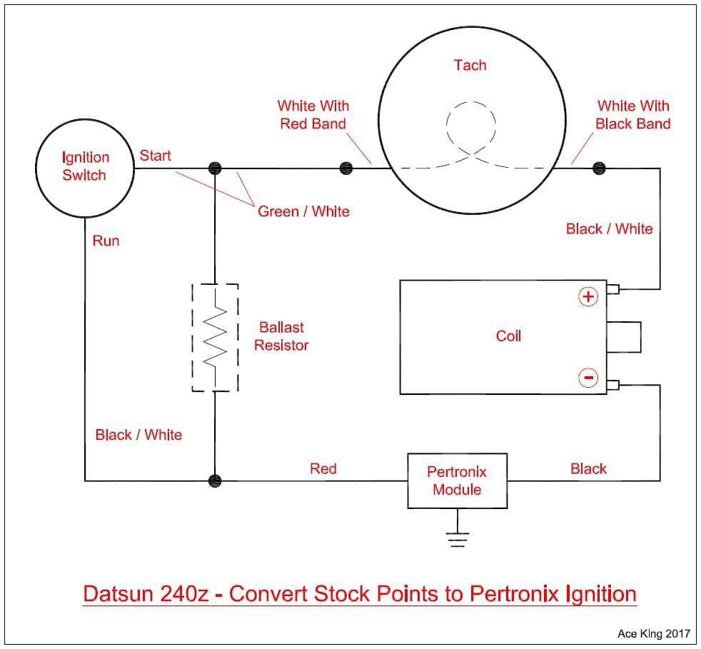
Hello, Have a few basic questions about installation of Haltech Elite 750, 73 240Z NA. Overlaying the Haltech wiring harness to the existing 240Z harness, can't get my head around some of the connections. First ignition wire (Key switched 12V) Which wire on the 73 240Z ignition switch is the switched 12v (on) ? (B.Y., B.W, W.R, L.R, or G.W) I have a FSM but not an expert on wiring diagrams. Terminate the existing ignition wire in the connector and replace with the ECU ignition wire or splice into the existing wire and leave it in the connector? The configuration is not typical and information is limited at best. Running a single HEI coil to a hall effect (reference and sync single) sequential distributor (cap and rotor, plug wires to SP). No coil pack (waste) or COP set-up. See coil pic. Second coil and resistor question. If I look at the 73 240Z wiring diagram (from ignition switch) B.W, and G, W connect to the resistor. Correct? Do these wires connect to any other components? B,W from the positive side of the coil connects to the tach, Correct? any other components ? The black wire on the negative side of the coil terminal, does this wire connect to or drive any other component in the existing harness? My concern is wiring the new coil directly to the ECU harness and terminating the wires from the (ignition switch, coil and resistor) will this termination impact other components in the existing harness? Any help would be appreciated.

-
-
Re: Haltech 750, premium harness/ 240Z What is the consensus for mounting the ECU and wiring harness location? Laid out / grouping wires and most for my application (L28 NA ITB) route to the left of engine compartment. Power / grounds for the ECU and fuel pump wires are the only wires traveling right and back. Anyone punched through the firewall just left of the hood latch cable grommet? Any issues with this location? Thanks.
-
-
-
Duffy, I purchased a distributor that provides two hall effect signals (CAS). Running a distributor cap and plug wires, no coils. https://www.efihardware.com/products/1752/distributor-full-sequential-for-Nissan-L-series-6-cyl Just want to wire the ECU to the ignition (on and off with key), distributor and coil (coil to the distributor). just the ignition for timing and advance curve tuning. Thank you for your help.
-
Hi Conedodger, Thank you for the response. As mentioned, sensor's are not the concern right now other then the CAS signal. Want to focus on wiring the ECU to the ignition only, for ignition and advance timing. The coolant temp, O2, TPS, MAP ATS will all be installed with the ITB's and the fuel management. I can loom Haltech wires/ harness those sensors for future install. A quick drawing of the haltech ECU connection points to the ignition, distributor (CAS) and coil would be assume. Sorry DA when comes to electrical schematics
-
Thanks for the response, Any wiring diagram or help you can share on wiring ignition side? ECU connected to ignition, CAS signal and coil wire set-up? Read your post on the tach conversion to your ECU, so would have assumed you've run down the wiring issues already. The tach is not my concern right now, purchased a 77 tach with the post style (negative coil terminal) internals. Will swap the tach internal at a later date. Thanks again.
-
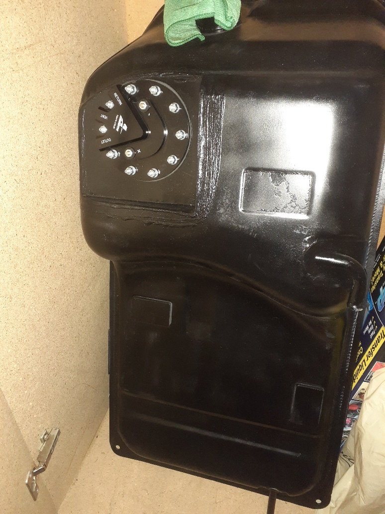
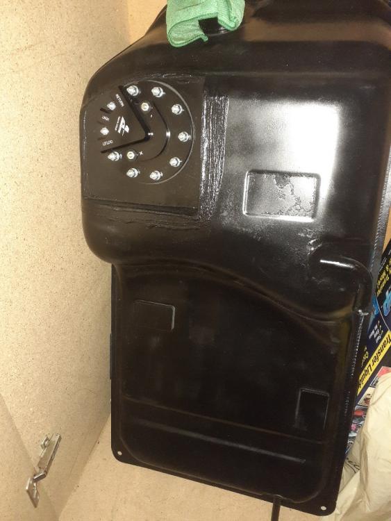
Hello Duffymahoney, Headed down the same path to EFI with a Haltech Elite 750. Accumulated parts over time, to mange the overall cost of the conversion $$$$$. Learning as I go but wiring, blending to the stock harness and fusing the system is a huge grey area for me. early vin 73 240z with a transplanted L28, N42 Block and head, round top SU's. No head work has been done thus far and a stock cam. My goal is to work out the bugs on the modern EFI conversion first (while the car is running and driving) then pull the engine for rebuild and head work and cam. Nothing radical. Convert in stages with a running / driving the car. First convert the ignition. I have the Haltech 750 unit and purchased the modern CAS signal distributor (link below). This unit can be installed with a cap and rotor or as a distributor less coil set-up. Gives you the flexibility of both options. I'll run the ignition with cap and phase the rotor. https://www.efihardware.com/products/1752/distributor-full-sequential-for-Nissan-L-series-6-cyl Confirm with Haltech the compatibility of the CAS signal from this unit. Question- what Haltech wiring harness did you purchase (or not) and how invasive to the stock harness is the ignition (only) conversion? All I want now is ignition tuning and advance curve set -up. Second phase - ITB's install and fuel management. My 73 came with the factory fuel pump wiring (at the fuel gauge sensor) but was fuel pump delete from the factory. Have a new cleaned and sealed stock fuel tank with an Aeromotive stealth in-tank fuel pump fabed/ installed, all the fuel filters and external fuel regulator. Waiting to purchase the ITB's. Thanks for any help with the Haltech ECU wiring to the stock harness, CAS signal and coil. I'll worry about the other sensor later, Map, coolant temp or head and O2.
-
Great choice! Tire fitment looks good.