


Captain Obvious
Community Member
-
Joined
-
Last visited
Everything posted by Captain Obvious
-
Embarrassingly... No. I have spring perches which have been removed from a pair of scrap front strut tubes, but I never procured a set of front struts on which to transplant the donor perches. I'm not confident in the success of this project to just go ahead and modify the struts that are currently on my car. I want another spare set to cut up. In any event, here's where I am now: I have recently started a couple different avenues to get my hands on a pair of front struts to finish this project, but haven't had anything delivered yet. And no... I didn't start trying again because you prompted me. I really did start a couple weeks ago. So, is anyone parting out a 260 or 280 that has a pair of front struts available?
-
That capacitor is just used as a filter for a local derived power supply to drive the clock. The diode and resistor are a simple voltage regulator to knock the battery voltage down to a lower level. And the cap is there to make sure the clock circuitry has a nice clean voltage from which to operate. It would be very unlikely for it to affect the operation of the clock, especially on the bench. Enjoy the extra horsepower. Haha! You talk like you don't know what you're doing most of the time, but I think, in reality you got skills. Well done!
-
Haha!! Very nice! I'm glad the solution was a simple bulb change.
-
Oh. Well that's too bad. That would have been easier to deal with. So we're back to needing a different thermistor, or a workaround for the current one. My read on the thermistor is that (within reason), the cold resistance doesn't really matter. As long as it's on the order of KOhm(s), it should be fine. And as for the hot resistance, as long as it's on the order of a couple Ohms, it should be fine too. But the absolute numbers have wiggle room. What's really important is that it's small enough that it'll heat up when you push current through it, but not so small that it'll get so hot that it can't be cooled by a gas bath. In other words, what's most important is it's ability to generate and reject internally generated heat. If it's huge and has big winged heat sinks on it that do a fantastic job of getting heat out of it's core, it'll never heat up enough to get into thermal runaway. Conversely, if the core is surrounded by an insulating layer, you won't be able to get the heat out of the center fast enough and once it's in thermal runaway, you won't be able to recover. This sounds, at first glance, what is happening here.
-
Yup. Most of them should all be the same. The glove box might be the easiest to get to if you just want to pull a bulb. That or maybe the ashtray bulb? Thought of something though... After all the years and PO's though, you should make sure you've got the right bulb. Original is Toshiba A12V3.4. There are other numbers that have been used over the years as replacements, but if you find that Toshiba bulb, you know you've got an original.
-
Got it. Dr. Dave, Did you drill out the holes in the ZCD version yet to see if getting more flow in there helps? I'm still not yet convinced this is a completely electrical issue. If you're reluctant to make modifications to a unit that you still might want to return, you could possibly simulate larger holes by encouraging flow? Read... "Wave it around in a cup of liquid (to try to force fluid through the little holes) while monitoring the state of the lamp."
-
So basically your summary is that the Toyota thermistor works great, but the ZCD part does not. And not only that, but the Toyota thermistor seems to work great* with two wildly different bulbs. Did I get that right? * Assuming you don't leave it on so long that you fry your 6V bulb by applying 12V to it.
-
OP. Glad you're making progress and got it running!
-
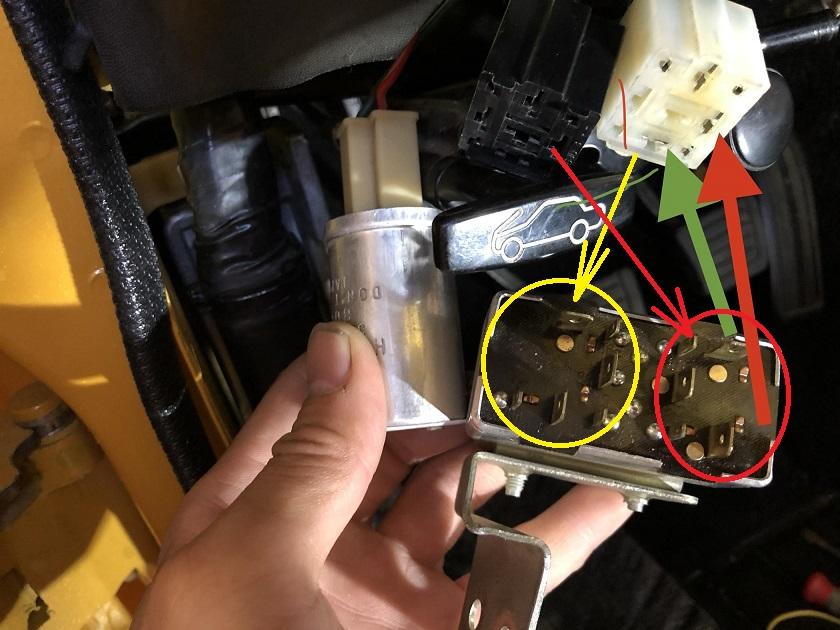
Agreed. They did a pretty good job of making sure stuff could only go together one way, but maybe they missed this one. I don't have the spare parts laying around to check for keys, but looking at the pics, I don't see anything. I had my FI harness out of the car a couple years ago to replace a bunch of the connectors etc, and I don't remember any issues getting that FI relay back in correctly. I suspect that after fifty years, my connectors just kinda fell where they belonged. Either that, or as you mentioned, I just checked where the populated contact positions were.
-
As Captain Obvious, I guess I just have to ask... You sure you don't just have the connectors swapped? Is it even possible. or are they keyed to only fit one way? I didn't look at any of the wiring diagrams to confirm, but I believe that all the populated locations do something. So just using the populated locations as a guide, I come up with this :
-
I don't think it's as simple as picking a 3K Ohm thermistor out of a catalog and tossing it in there. The 3K is the room temp resistance, but that's not the only important reading. You also have to know how it responds to temperature. @Dave WM If you had an environmental chamber, you could rig up some way to temporarily hold a test lead to the other side of your thermistor remains and plot it's temperature characteristics.
-
I just grabbed a pic of some random thermistor. I wanted something that had leads on it and a pic that wasn't so big that it filled the page. Don't try to read any engineering into my choice for that pic. But... It's a 4.7K from Vishay: https://www.vishay.com/docs/29049/ntcle100.pdf
-
I was thinking the same thing. I wonder if it was just measured at a different temperature, or if ZCD has used multiple different thermistors.
-
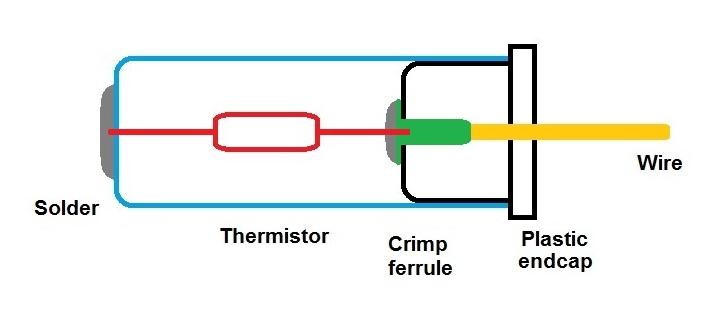
I updated the pic above to show more details about how I think the crimp ferrule is used to transition from device lead to wire.
-
Yeah, I'm thinking that inside that black cap there is a ferrule crimped onto the end of the yellow wire. That ferrule would be crimped onto the wire at one end and have a flat disk with a small hole in the other. Stick the thermistor lead through the hole and solder it to the disk. Transition from the semi-rigid thermistor lead to the flexible stranded wire. Of course, I've never even held one of these things in my grubby hands so it's all speculation and analysis from afar.
-
You ought to be able to de-solder the lead from the can and then just pull the plastic cap out with the thermistor along with it. (If the whole thing isn't too fragile by now...)
-
Dr.Dave, Yep... There's the other end! DaveWM, I assume there used to be some sort of discrete component in there, but honestly I don't know enough about thermistors to answer your good question about just a length of wire that changed it's resistance with temperature. I guess it's a possibility? Maybe? I think it used to look something like this and the thermistor turned to dust: I also don't think there is anything buried inside the plastic end cap. I think that's just a device to transition from the thermistor lead to the flexible wire.
-
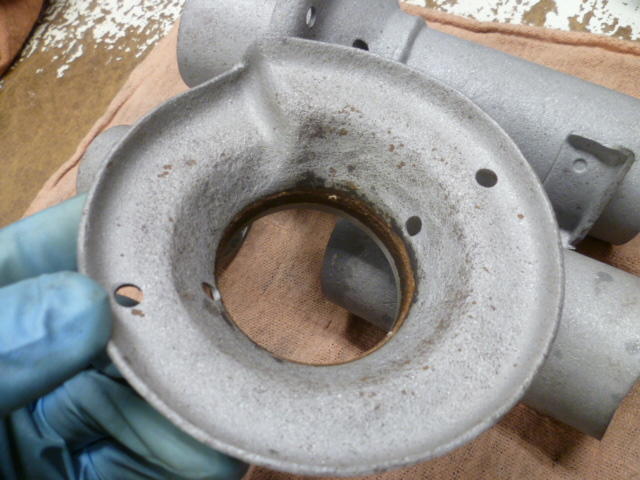
SteveJ, thanks for putting the video on youtube for me. That worked. And Yarb, thanks for the video. So Dr. Dave, are you able to see the remains of the thermistor body down inside your outer housing? In this pic, you can see the solder blob on the outside where they made connection to the other sensor lead. You should be able to see some of that lead inside the case:
-
Yarb, I don't know if it's just me, but I couldn't get your video to work. It downloaded, but it was a blank screen. Probably a problem on my end, but can you do youtube instead of hosting it here on the forum?
-
Dr. Dave, Great photos of the failed original sensor. I did a little google searching on the internets for that part number (as I'm sure you did), and came up blank. I suspect that number is the part number for the ASSEMBLY, not just the thermistor. The thermistor itself is probably a small chicklet device with two leads on it. Just as a rough idea: Looks like they soldered one lead to the wire embedded in the black plastic cap, and then they slid the thing together making sure the other lead poked out a hole in the metal can. Then they clipped the other lead off and soldered that other lead to the can. So in the end, you've got a one wired device with the other connection coming back through the chassis mount. You pulled one lead out with the black plastic end cap, but there should be more to it. Either the rest of the device has turned to dust as a result of the heat, or may still be stuck down inside the can. You pic is too dark for me to see inside the can, but there is more still in there. All that said, I think your analysis about the locations and sizes of the holes might bear some additional scrutiny. It seems unlikely to me that after being submerged in the fuel tank for hours, being shaken around by driving, that the air bubbles would not have worked themselves out of the ZCD sensor, but who knows. And if that sensor is sitting in a little air pocket, it could certainly behave exactly like the problem you're seeing.
-
Sadly, I will not be making the trip this year either. For those of you who attend, please stay safe, and I hope it's a fantastic event!
-
The original reference to Darmok is from a Star Trek episode where they encountered a race that always spoke in metaphor. In that situation, you can understand the WORDS, but they really mean nothing unless you have a shared past experience. For example, you could ask "How is the weather?", and I could answer "Dave WM and Captain O riding in the Z." Haha!!!
-
Dave. Dave! Come back!! Dr. Dave asked you a question: Haha!! So Dr. Dave, I don't think there would be a lot to be learned from a post mortem on the dead one. The only really interesting thing would be to characterize the thermistor against a temperature curve, but if it's open circuit, that won't be possible. I guess there's a tiny but non-zero possibility that the open circuit break is somewhere I could see and kluge together long enough to take some measurements. There is also a tiny, but non-zero possibility that there might be a part number on the outside of the sensor? Up to you if you want to waste the dollar it would cost to mail it.
-
Dr. Dave using stone knives and bearskins.
-
So Dr. Dave, Can we drop back one last time... Is there any possible way your thermistor is NOT dunked in gasoline at half tank when the light comes on? I know you verified that the holes allow liquid to enter the sensor. Is there any possibility that the location of the holes is important? Stagnation perhaps? Does your old thermistor on your original fuel sender unit still work? If so, any thoughts on swapping the two and getting on with life? Want to send me some parts and I'll see what I can do with them?


