


Captain Obvious
Community Member
-
Joined
-
Last visited
-
You think the brake issues are related to the balance tube? What are you doing instead for brake vacuum if you aren't using this balance tube?
-
@Mike This bot is still at it. I hit "report" on this thread and the previous one as well.
-
Have you put a vacuum gauge on the balance tube to see how the vacuum looks? I'd try it at both your more centralized PCV connection, and also at your brake booster connection on the end. Just to see if you can glean any useful info from the gauge?
-
Or maybe.....

-
Oh, and what caught my eye first was the mention that it was "For a ’72 240Z". Like the year matters for what film would work. So by saying it out loud, I guess I'm risking making the bots better, but that's what really started me wondering.
-
Well honestly, those were my words. I was trying to highlight the fact that it looked fishy (to me) that someone would go through the time and effort to create a brand new account... Just to say that useless thing. 🙂
-
@Mike
-
I believe that piece of plastic is known as a "strain relief". The purpose is to help prevent damage to the softer delicate fusible link wire when you are pulling on the harness. In other words, if you pull on the wiring, that plastic strip is supposed to protect the link wire. But yours, like so many others is broken and not doing anything.
-
That method will not work for the Z because the Z ignition lock uses a solid pin for retention, not a roll pin. I mean, I guess you could drill directly into the pin and then thread it and use a puller to yank it, but the geometry is all just so small. Last time I removed a pin, I drilled into side of the lock cylinder (figuring that I didn't care if there was a hole in it since I was replacing it anyway). Something like this:


-
Hahaha!! We all have our strengths. 😀
-
You get the picture. https://www.youtube.com/watch?v=-9NMt42il4Q
-
Sorry, I'm further out on my limb than I should be. I said "from what I've seen", but in reality, I should have said something like "I've not had direct experience with the new OEM knobs, but as discussed here on the forum...." So let me try again with that in mind. I've not had direct experience with the new OEM knobs, but as discussed here on the forum, Nissan changed the size of the shift knobs somewhere along the years. The knobs originally supplied on the Zs are smaller than what was supplied as a replacement some years later. As for the timing, the first time I saw mention (with supporting pics) of this situation was in 2006. Posted by Arne: https://www.classiczcars.com/forums/topic/20489-restoring-origional-shift-knob/page/2/#findComment-189573 There was also a second confirmation about the size change where GongZ bought a new "Genuine Nissan" and the set out to maybe modify it to the original smaller dimensions: https://www.classiczcars.com/forums/topic/44587-5-speed-knob-reproduction/page/7/#findComment-408076
-
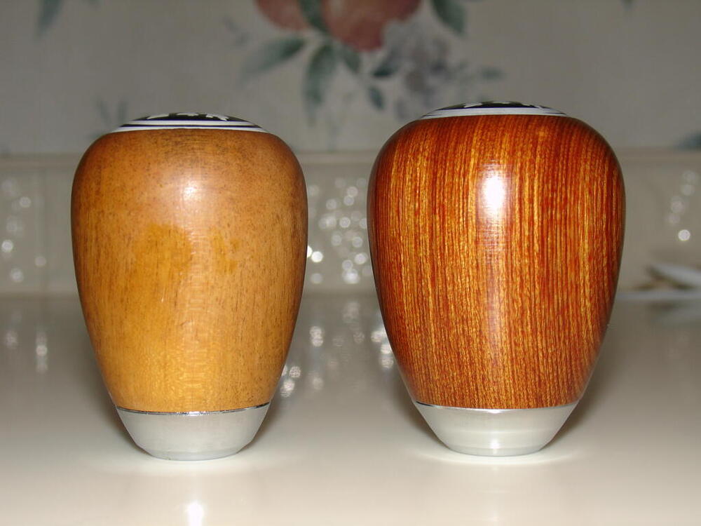
Yes, from what I've seen, Nissan changed the size of the shift knobs somewhere along the years. The knobs originally supplied on the Zs are smaller than what was supplied as a replacement some years later. Here's a pic showing an older original Z car shift knob and a genuine OEM replacement that could be purchased some years later. Both are genuine OEM, but the newer version is larger than the older original. Original 240 knob on left, newer Nissan replacement on right: So yes... For your car, NOS isn't good enough. You want an "ONOS" (Old New Old Stock). 🙂 I thought I had pics of the ONOS knobs I have here, but I can't put my finger on them. I'll have to take some fresh pics when I get the chance.
-
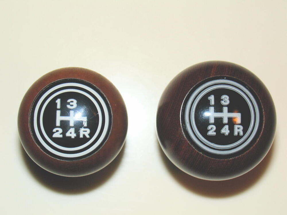
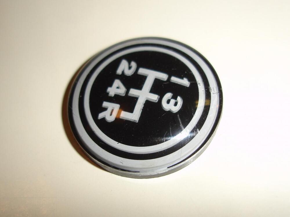
Beautiful car. I'm certainly no expert, but I think I see a couple minor things that are not quite correct. For example, I don't think the shift pattern emblem on the shift knob is quite right. It looks like a flat bottom (presumably second surface screen printed) emblem instead of the reverse embossed that was originally used. I don't see the "depth" that should exist on the shift map: This pic shows the 3-D "depth" of the original map: And (hopefully not being too self-serving), I've got a beautiful NOS shift knob on the shelf here if you're interested. Haha!!
-
@Yarb https://youtu.be/Or4Fq31kl3Q?list=RDOr4Fq31kl3Q


