Zed Head
Community Member
-
Joined
-
Last visited
Everything posted by Zed Head
-
What's a c110? Maybe the switch at the brake pedal is stuck. Check that power is on both wires when you press the pedal, one wire when it's up.
-
It's not recommended to remove your battery cable like that, but since it's done and the car stayed running, it is obviously producing electricity. Is it possible that you have actually corrected all of your problems from the first few posts, with the wiring and the bad alternator (you did make some wiring fixes and the alternator is new now), and that you've been trying to verify the repairs with a bad voltmeter? Maybe everything is now working correctly. Might be worth driving to a shop or the parts store and getting a second opinion, with a second set of diagnostic equipment, on the running car.
-
If you're using the adapter tube that comes with many testers, it will lower the value at the gauge. The adapter/extension tube in my set lowered the reading from 180 psi to 120 psi. It adds volume.
-
This diagram shows the fuse as "inline". http://www.atlanticz.ca/zclub/techtips/wiringdiagrams/240z/1971_240z.gif The 1971 FSM Supplement shows a 20A inline fuse right next to the fuse box, on the wiring diagram. On the green wire. You can get the Supplement on the xenons30 site. http://www.xenons30.com/reference.html
-
I was wrong on when the ~ 3 volts or less are on the L wire. It is low voltage when the connector is plugged in, and the key is On. That completes the connection and lets the lights and relays drop the voltage. No current flow, no dropped voltage. I just checked on my car again. I had 12 V at the connector, unplugged, with the key On, and 1.8 V measured at the back of the plug when it was connected and key On. Sorry about that. Based on what you're written, unless your alternator is damaged it should be charging. You said that your charge light works (goes off when the engine runs) so that should mean that it is producing a charge. When your charge light goes out, that basically means that current is not flowing "from" the battery any more. So the fact that your charge light goes out must mean that you're getting some output. I have read that using your alternator to charge a dead battery is very hard on it (another voltage spike situation). Something to be aware of. SteveJ's suggestion to read the front and back of the EE section is good. I'll bow out now and avoid confusing things anymore.
-
I am not positive that the L terminal on a Nissan alternator will not take 12 volts. Your alternator may be okay. But I do know that the components of the internal regulator do not like current spikes (eg disconnecting the battery while the engine is running). You should probably take your alternator to an auto parts store and make sure it hasn't been damaged. You might be wasting your efforts on an alternator that will never charge. For the record, I measured 2.5 volts on the L wire of a 1976 car that has been converted to internal regulation. Maybe 1978 is different but it seems like if your charge light is on and your brake check warning light relay is activated and your ignition relay (as shown by the diagram on EE-15), that you should not get 12 volts on that wire, when everything is connected. The charge lamp and relays should drop the voltage, leaving less than 12 at the L wire. So something is off, either my understanding or your PO's wiring.
-
-
It looks like you're reading battery voltage at the alternator and that the alt is not actually doing anything. Do you have the L wire connected? It should get ~2.5 volts at the connector when the key is at On. As I understand things, the L voltage magnetizes the alternator coils so that they will produce electricity when the alt spins. The charge light (the Lamp that L refers to) should be lit when the key is at On, engine not running, and go out when the engine starts. If the alternator is not producing voltage greater than battery voltage, the light will stay on. That hanging wire that goes to the brake check relay is also the power for the Lamp. They are wired in parallel. As SteveJ suggests, you'll see it on Page EE-15. You should read ~14.8 volts at the battery terminals at about 2,000 rpm when the alternator is working and wired correctly (depending on load, like lights, fans, etc.
-
In looking at the U/Ub diagram you can say that Ub is definitely affected independently of U, by the off-spec. 126 ohm value, but can't say for sure if U is affected at all. I was hoping to be able to calculate some real numbers but can't do it with the Pin 8-9 measurement. Pin 8-9 measures R0 (100 or 126 ohms), so that affects Ub. But pin 8-6 includes the potentiometer and R10. If the potentiometer has higher resistance, then U and Ub might effectively cancel out, for the purpose of the AFM. But if R10 is the higher resistance and the potentiometer is unchanged, then voltage Ub is effectively lower (the sum of the resistances is higher) and the ratio is off. U/Ub would be higher than expected, which would create a lean mixture from the ECU (based on the fact that voltage is higher with the vane close - less fuel needed)). Since it is split and starts at 1:1 (the penny/quarter data) I would estimate the voltage error back to the ECU could be 12.5%. The highest voltages are sent at low rpm so low to part-throttle would be lean. There could be a logic error in all of the writing above, but in short, you can see that it is possible that the potentiometer resistance that affects U is unchanged. Therefore the U/Ub relationship could be off, with the higher 126 and 226 resistance readings. I almost bought one from Python Jenny. They didn't have mine in stock though so I went with MSA. Since you have three AFMs now maybe you could measure the voltage ratio of at least one, with closed vane. You should get about 50% of the input voltage across 7 and 8 with power in at 6 and 9. Any low amp battery will work, even a C or D cell. If you get 50%, then I will move on from the resistance readings, until some future date. My car is a 1/76 build and had the A31-060-001 AFM. It took me a while to get this all down so looks like I missed a bunch of new posts. No time to read them right now. Good luck.
-
I agree on the voltages. That's the purpose of the quarters/pennies procedure. f the AFM shows 50% of supply voltage closed and essentially 0% open, and a smooth change with vane movement then the electrcial circuit should be in good working order. I don't necessarily agree on the acceptable resistance readings. As I suggested earlier, 25% is a large variation when you're talking about measuring how much air is entering the engine. As the voltage output experiments have shown, the AFM is just splitting the voltage in half, and, most likely, using one side to determine air volume. I haven't done any electrical calculations for years, but maybe you could determine and compare the voltage split of a 100/180 potentiometer to a 126/226 potentiometer. Then we would have the difference in voltage output of the two, closed, open and in-between. Sorry it's not working for you Jenny. Re the pennies - I had pondered that. Best to get a balance and use known weights in the future.
-
Whoa. A shocking start to the morning (West Coaster). Where did you get it? And, just to confirm, what brand of ohm-meter are you using? I had to buy a new one when I started working on my car, because my old (very) Radio Shack analog unit wouldn't cut it in the low resistance range. Something is not right. Anthony G. in Post #201 got 186 and 103, I have a 76 and a 78 that both get ~180 and 100, and those are the specs. from the FSM. If your ohm-meter is working right, at the least you have received an out-of-spec. AFM. I bought my reman, AFM from MSA and it had a sticker on it from Fuel Injection Corp. POS = Previous Owner's Stuff?
-
B is for Battery. Just run a jumper from the positive terminal of the coil. When the coil is powered, the module will be powered. Or if you're mounted by the old module, find out which wire is powered when the key is on. There are different views on the RPM limit, some say it was actually due to the coil not the module. Others point out that 4500 rpm for a V8 is 6,000 rpm for an L6 (sparks per revolution conversion). Good luck. Make sure that you have a good ground to the mounting hole metal. A bad ground will kill the module, otherwise it's very durable.
-
I found this web page helpful even though it's aimed at 510s. The wiring to the module is correct and described in component terms instead of colored wires. One thing it leaves out that is very important is to make sure that there is a good connection from the mounting holes to ground. I ran a dedicated ground wire from the hole with the grounding ring. http://dimequarterly.tierranet.com/articles/tech_hei.html You won't have to do any of the breaker plate instructions, you don't even need to get in to the distributor. I have seen people mount these in the engine compartment or next to the module in the cabin. The advantage of the engine compartment is that you can just run two extra wires from the coil to the module, and just disconnect the distributor wires from their junction box and connect them to the module. Disconnect the plug from the original 1978 module in the cabin and it's ready to go. Use your judgment on insulating the hanging plug, some wires will be hot but they won't do anything. If you mount in the cabin, you'll need to do a little more work to figure out what wire comes from where. I picked up a small project box at an electronics supply store and a junction strip for the wires and put everything inside, then mounted it in the engine bay where a harness holder had been.
-
That is a ground wire. The switch just completes the ground when the engine is cold. The thermotime switch only works to shut off power to the CSV when the engine gets warm or when it gets hot from usage. It would only affect starting. You probably have a four port housing, but since you don't have the water temperature switch for the extra pickup coil (1976 Federal, like I have) they just put a plug in the extra port. That does look like a tight fit. I had mine off to do some manifold work when I put a new one in so can't tell you how to get in there when it's on the engine. Good luck.
-
By your wiring diagram the wire from the lamp is the blue one at the harness plug to the regulator. By the 1982 diagram, this wire should connect to the bottom of the T switch, identified as L. The atlanticz swap page shows the same thing. Blue wire from plug connects to the bottom leg of the T plug. Blue to white wire w/black stripe. Here is the link that I looked at that said explicitly that the Lamp circuit needs less than 3 volts. It is for a GM alternator. I got curious and measured the voltage on mine and I got 2 1/2 volts,to confirm the same on the Z. The blue wire is after the lamp on the power circuit so it should not have 12 volts since the lamp is a resistive element. If you're measuring 12, you must have it hooked up to the battery or a switched 12. http://www.hotrodlane.cc/ONLINETECH/CS130DREG.html Here is the atlanticz page for reference, look down at the bottom to see 1977. http://www.atlanticz.ca/zclub/techtips/alternatorswap/index.html When I did the alt swap I ended up with one extra hot wire and one extra switched wire. Your original swap may have been done incorrectly. Might be worth pulling apart the splices under the hood to see what the PO did. Just follow the wires from the alt, there should only be four or five, S, L, power (B+), ground (E) and maybe a capacitor wire.
-
I think that internally regulated alternators can be damaged if they get more than ~3 volts on the L wire. The L wire is the wire that goes to the lamp in your voltmeter. You can check it at the T plug before you connect the alternator by turning on the key and measuring. If you get battery voltage, you need to rewire to the voltmeter lamp or put a resistor in line. The other wire is the S wire and should measure battery voltage.
-
I ran 50 pennies, using 24 lb paper, and 5 staples. Battery voltage was 9.33 to start (colder in the garage). I got 0.68 volts out or 7.3%. Close to yours but with the heavier paper and more staples, should have been a lower output. It would be nice to see what a "bad" one reads. I sent mine to MSA for the core.
-
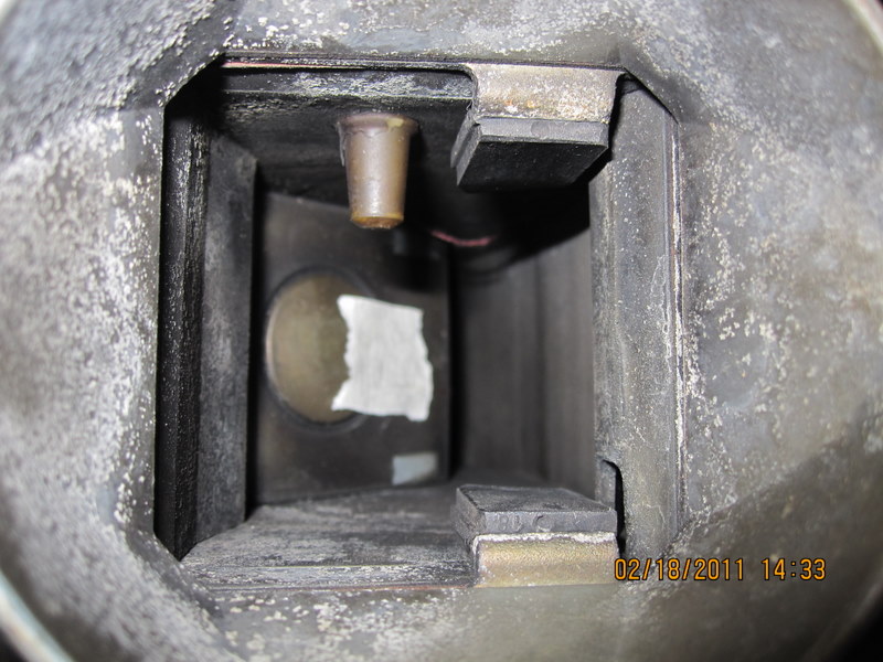
In Post #26 hogie said 1 3/4" pressure plate height. But I think that is the new one. Maybe. He said he had ordered one from NAPA. hogie, right now your only point of reference is your old collar and your old pressure plate. If you measure those, you'll know your starting point for comparison. So far, I don't think that you have told what the old parts actually measured, beyond the picture of the collar and the tape measure. It would be great if you could measure the old stuff, so that there would at least be confirmation of something that didn't work OR maybe it would point at the slave cylinder and rod. Then compare it to the new stuff. My two examples above, Post #27, give a range of 3 3/8 to 3 13/16" for the height from the bottom of the pressure plate to the top of the ears on the collar, combined. That would be everything that fits between the fork and the pressure plate fingers. These two measurements both worked, one 1 3/4" and one 2" pressure plate, same collar. This comes up all the time but rarely are any measurements reported. Overwhelmed yet?
-
I hope we don't get banned for what's going on here... FW, if you could run the 28 quarters, we could see if an 82 AFM has the same spring tension as a 78 AFM. Or at least the equivalent weight in pennies. It appears that you have a balance of some kind. It looks like the AFM is designed to simply split the input voltage in half, then scale it to full potential on one side of the potentiometer and zero on the other as the vane travels from closed to full open. The ECU uses one of those voltages for its injector time calculations. Also, you can see from your chart how you lose the leverage as the vane drops past perpendicular. Each new penny has less effect. Were you tilting the AFM to avoid the rubbing or not?
-
Howdy hogie. It does look different than old factory stock but the necessary bearing surfaces are there. The tops of the ears and the bearing and the spring clip are the only contact points. If you look at Carl's pictures in Post#31, you can probably figure out where to measure from to see what you have. They sent you the collar/sleeve with no bearing, so you'll have to measure from the top of the ears to where the top of the bearing would be. It does look like a short one though. Maybe a 240Z collar/sleeve. If so, it certainly won't jam your clutch partially open, but may not disengage it fully either. You might need an adjustable slave rod. Edit - actually it looks like it might be designed to handle two different bearings. I would guess that your bearing will only press up onn the narrow section, so it is probably taller than it looks in use. If you have a bearing, you could guesstimate where it will end up once pressed on take a measurement there. I looked back at your pictures but can't read the tape on your measurements. How does the new one measure out compared to the old one?
-
Here is a single mid-vane data point if anyone ever has the urge to see where their AFM falls in comparison. 1978 AFM 9.62 volts across pins 9 and 6 Output measured at pins 7 and 8 AFM bore pointed down and leveled Mid-vane measurement taken with a taped roll of 28 quarters hanging by a thread from the edge of the vane. Vane Closed 4.74 volts (49 % of input) Vane Open 0.12 volts (1.2 % of input) 28 quarters 0.488 volts (5.1 % of input) The first two measurements tell about the potentiometer and the last one tells about the spring tension. The vane was only partially open with 28 quarters hanging from it. I tried 20 quarters but the thread rubbed on the housing and I could not get a consistent number. I have attached a picture so that you can see how far open the vane is with only 5.1 % of the input voltage going to the ECU. This might seem like some nonsense but it's pretty interesting. If you consider that the ECU is also using small resistance readings fromthe various temperature sensors also, it's easy to see how things can go wrong. Note that this AFM ran well on a parked car, and had normal (100 and 180) resistance readings but I have not actually used it under load. Except for starting the car in gear on jack stands and applying the parking brake while the wheels were turning, to test it. It sounded good. Fun, fun, fun...
-
A flow bench would be the best way, considering the application. I wonder how the rebuild guys do it. There is leakage past the vane, plus the offset from the air idle circuit. I found that my rebuilt AFM had enough air going through without moving the vane that, after advancing my timing, I had to adjust the fuel pump cutoff switch to only work when the vane was just barely open. The engine almost had enough air through the idle circuit and leakage to run without any vane contribution. The idle air circuit will change the liftoff point of the vane, I used it to keep my fuel pump switch from cutting off for a little while. I had to lean the idle air back out for Oregon emissions though (eventually I just bent the fuel cutoff switch arm to make it work). I already tried a few things with a roll of quarters on top of the vane but the only way to be reproducible, in my opinion, is to hang a thread from the edge of the vane, so that the lever arm length is consistent. Basically, I ended up where atlanticz did. But I think that one measurement, with the vane perpendicular or midway, is all you would need since you can't change the spring constant (edit - actually, maybe you can, with the other screws inside the AFM, I haven't been that deep) and you can only change the preload by rotating the wheel. I would say that using atlanticz's method of attaching the weight, but using a known reproducible weight (rather than pop cans and water), hanging that weight and measuring the voltage ratio, volts in at 6 and 9 vs. volts across 7 and 8, would give you the best calibration number to try and match. (second edit - the main purpose of this exercise is to compare AFMs, voltages to the ECU, I think, known good ones vs. others). I'll go hang a known number of quarters from the vane and measure the voltages. That's really the best it will get without a flow bench, I think.
-
I'll see if I can come up with at least a one or two point calibration number using a 9 volt battery. Maybe a fishing weight or similar hanging on the vane. My beer comes in bottles. The hard part in these situations is coming up with something reproducible. Using common coins as weights might work.
-
Running rich will make quite a stink. My 76 with EFI stank bad until I fixed the fuel pressure regulator. Maybe you just need a little more tuning at the idle and low rpm end.
-
You could also put it in high gear and roll it by grabbing a tire and turning it. An alternative if it's a manual.