Leaderboard
-
HS30-H
Free Member4Points5,509Posts -

ZNate
Free Member4Points51Posts -
motorman7
 Subscriber
 3Points2,228Posts
 -
brunodoggy
Free Member2Points67Posts


Popular Content
Showing content with the highest reputation on 08/17/2020 in Posts
-
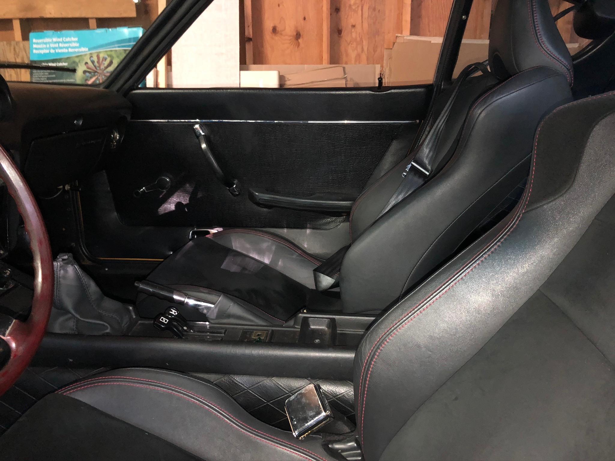
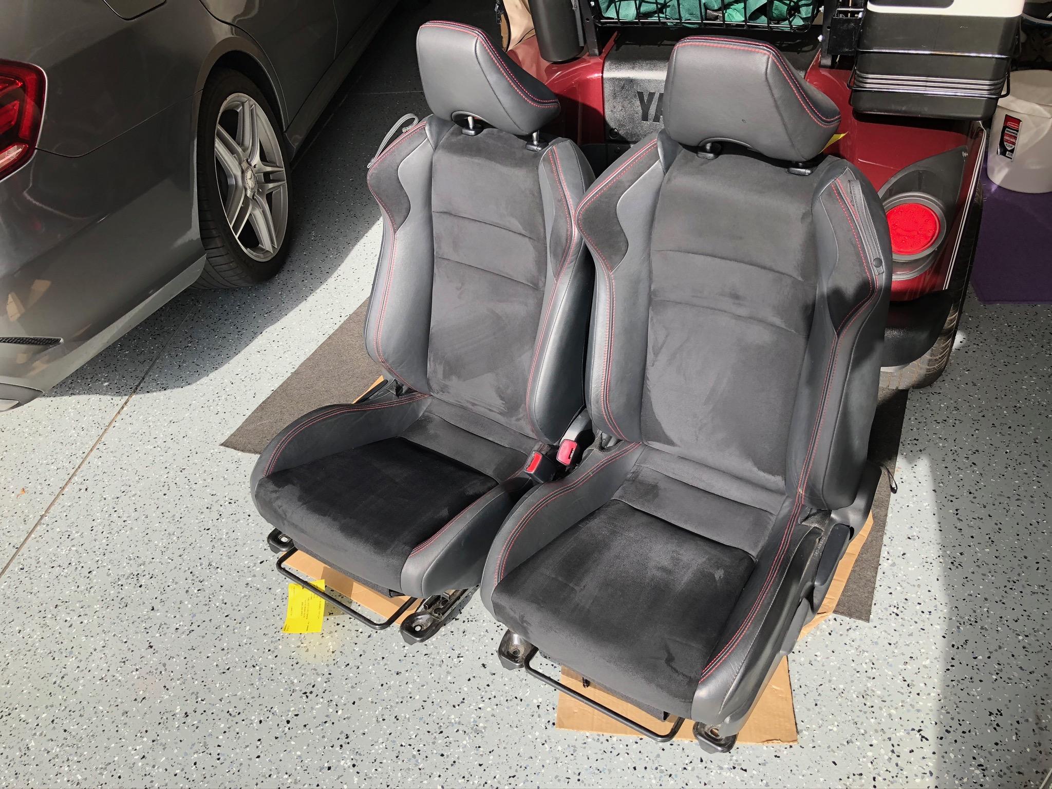
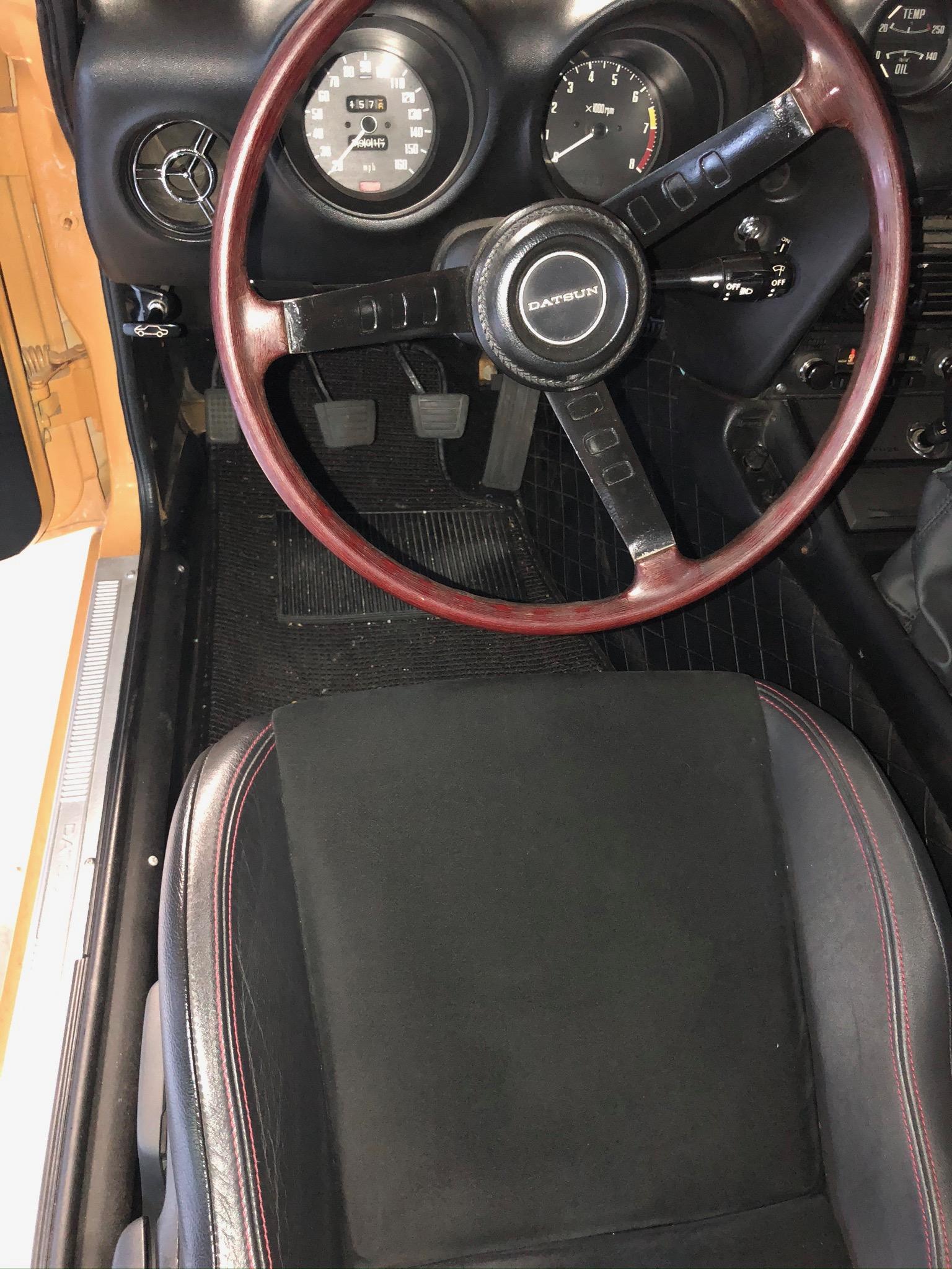
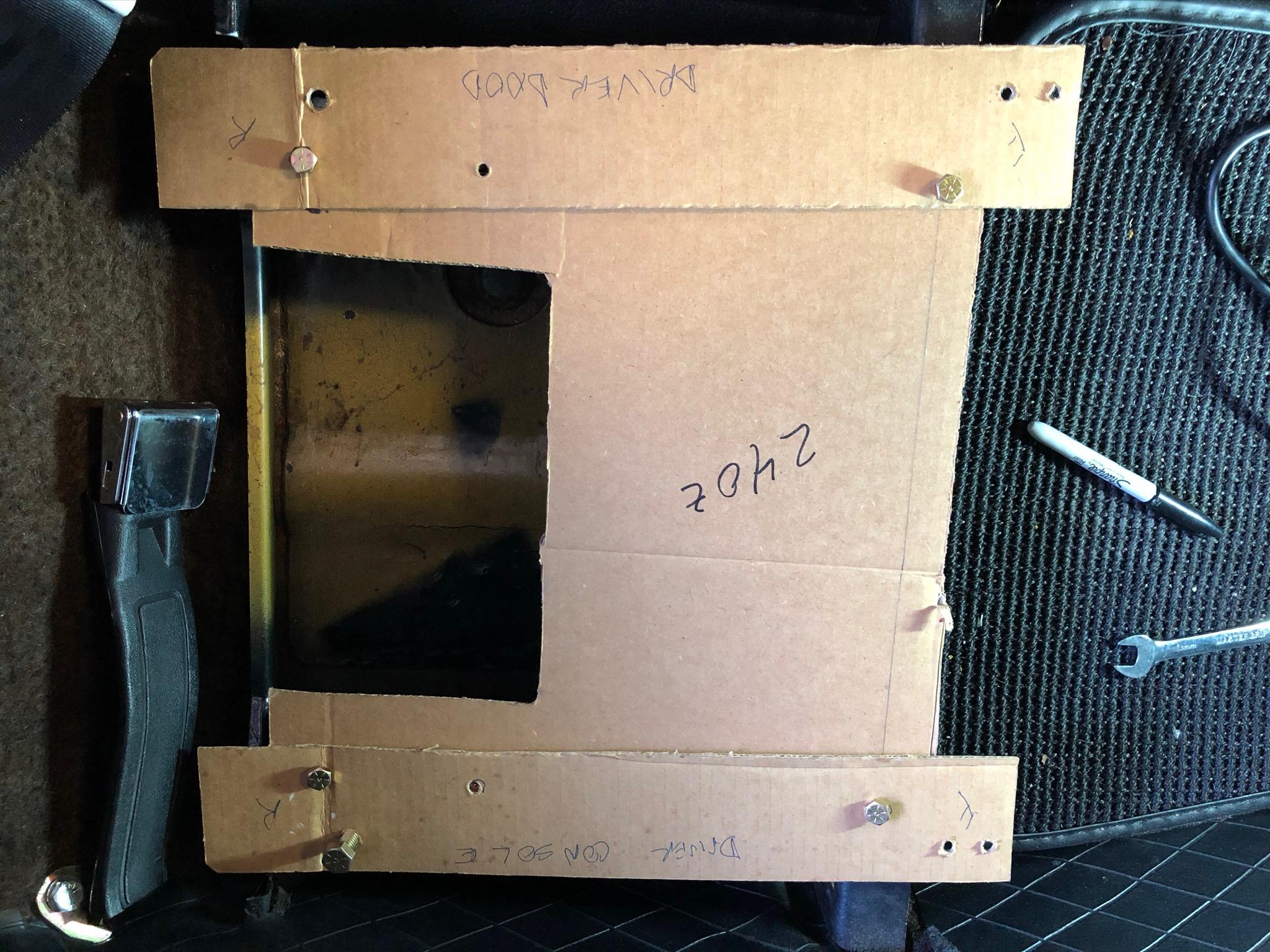
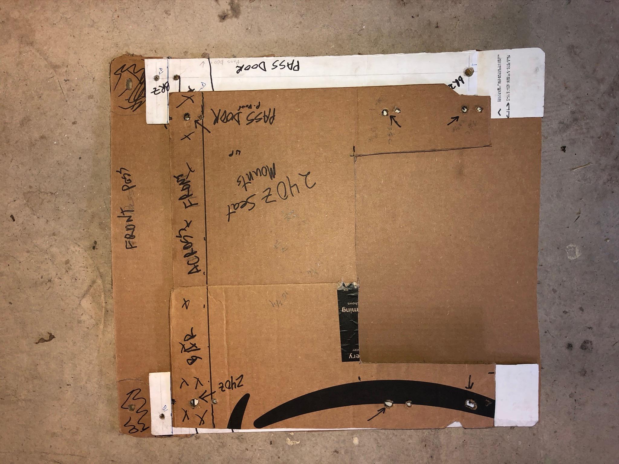
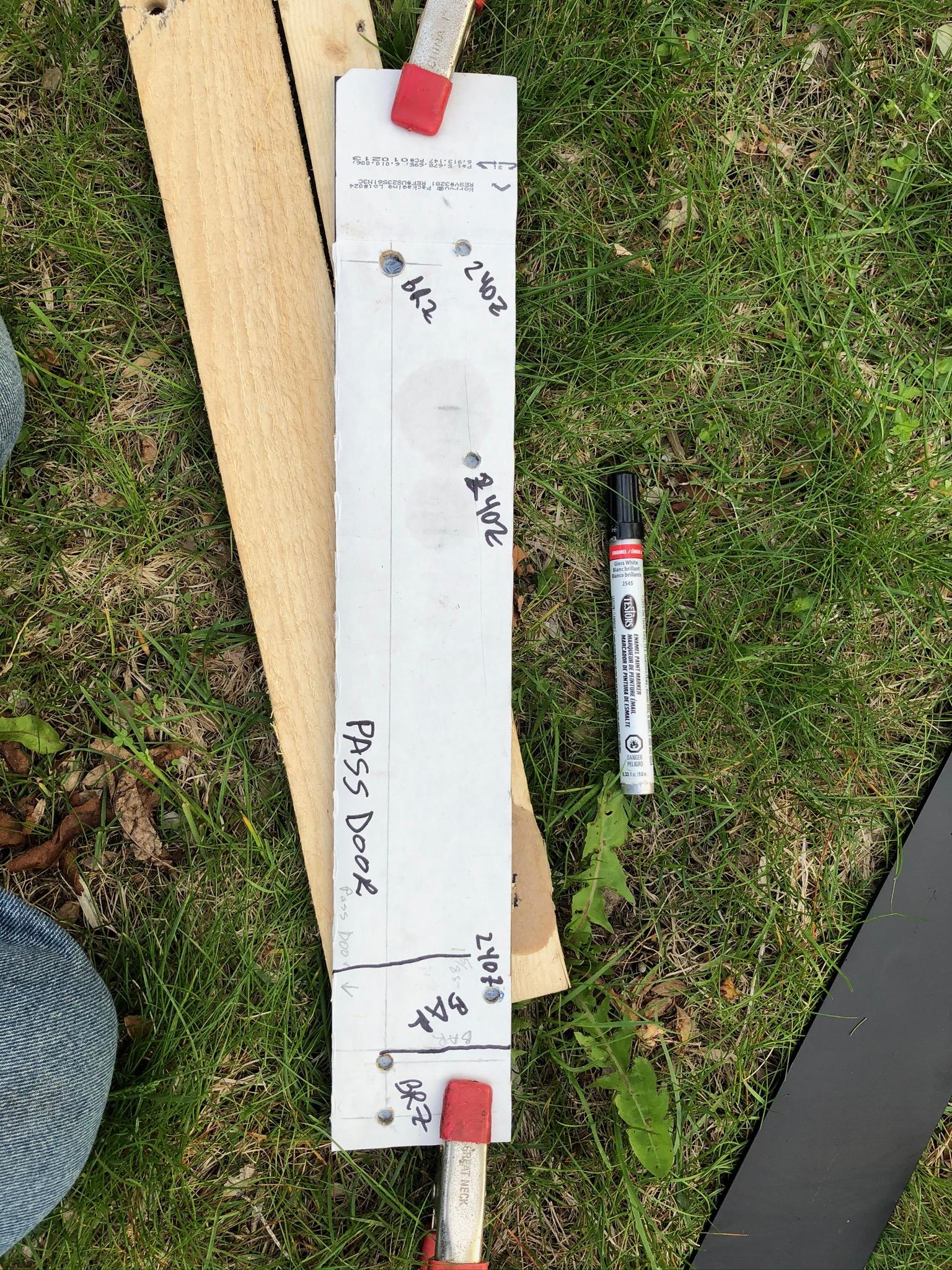
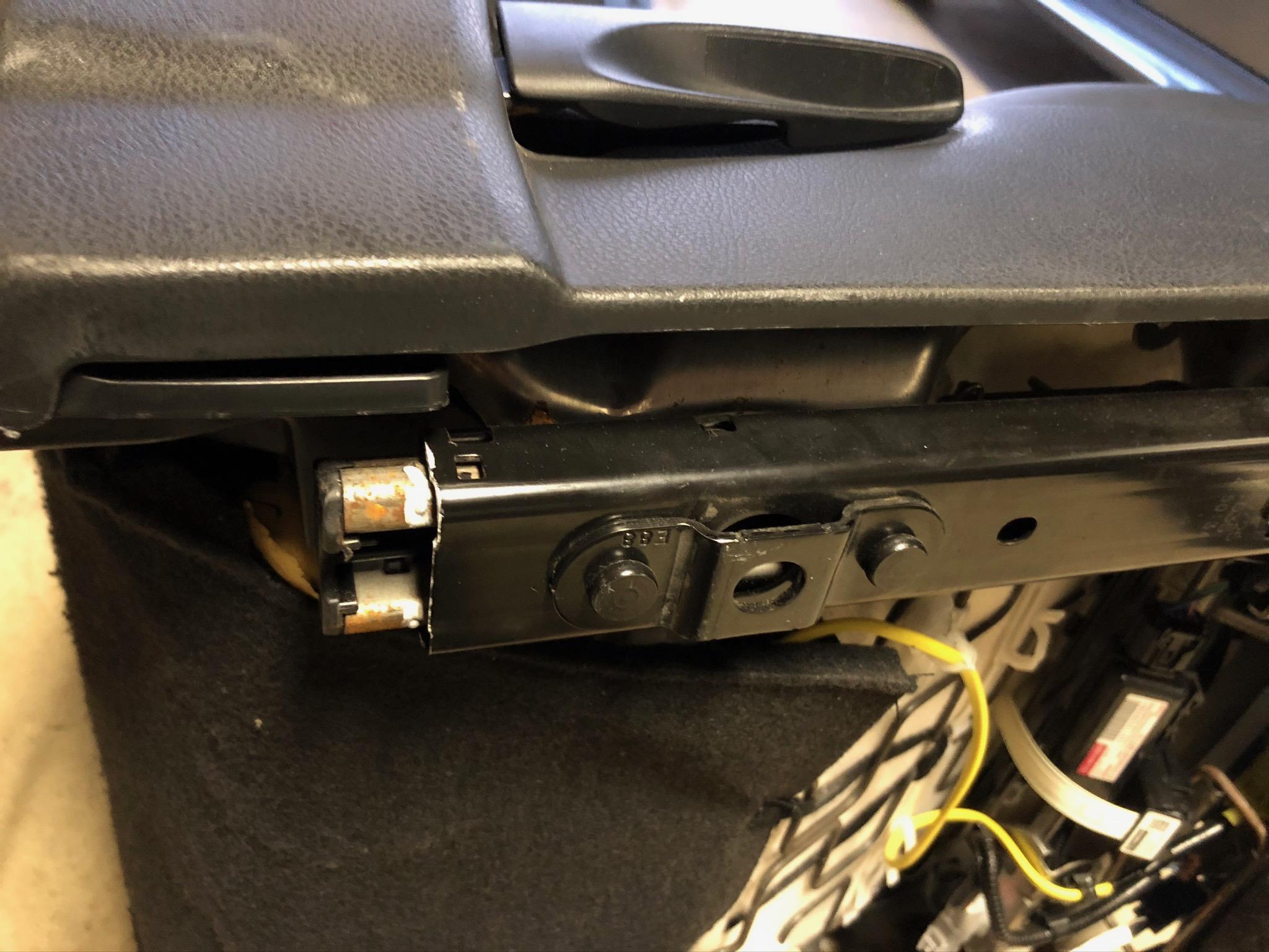
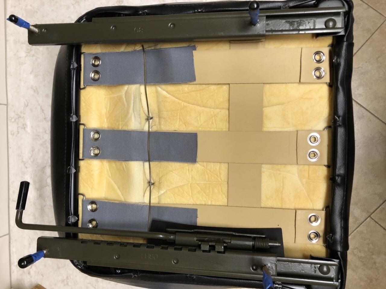
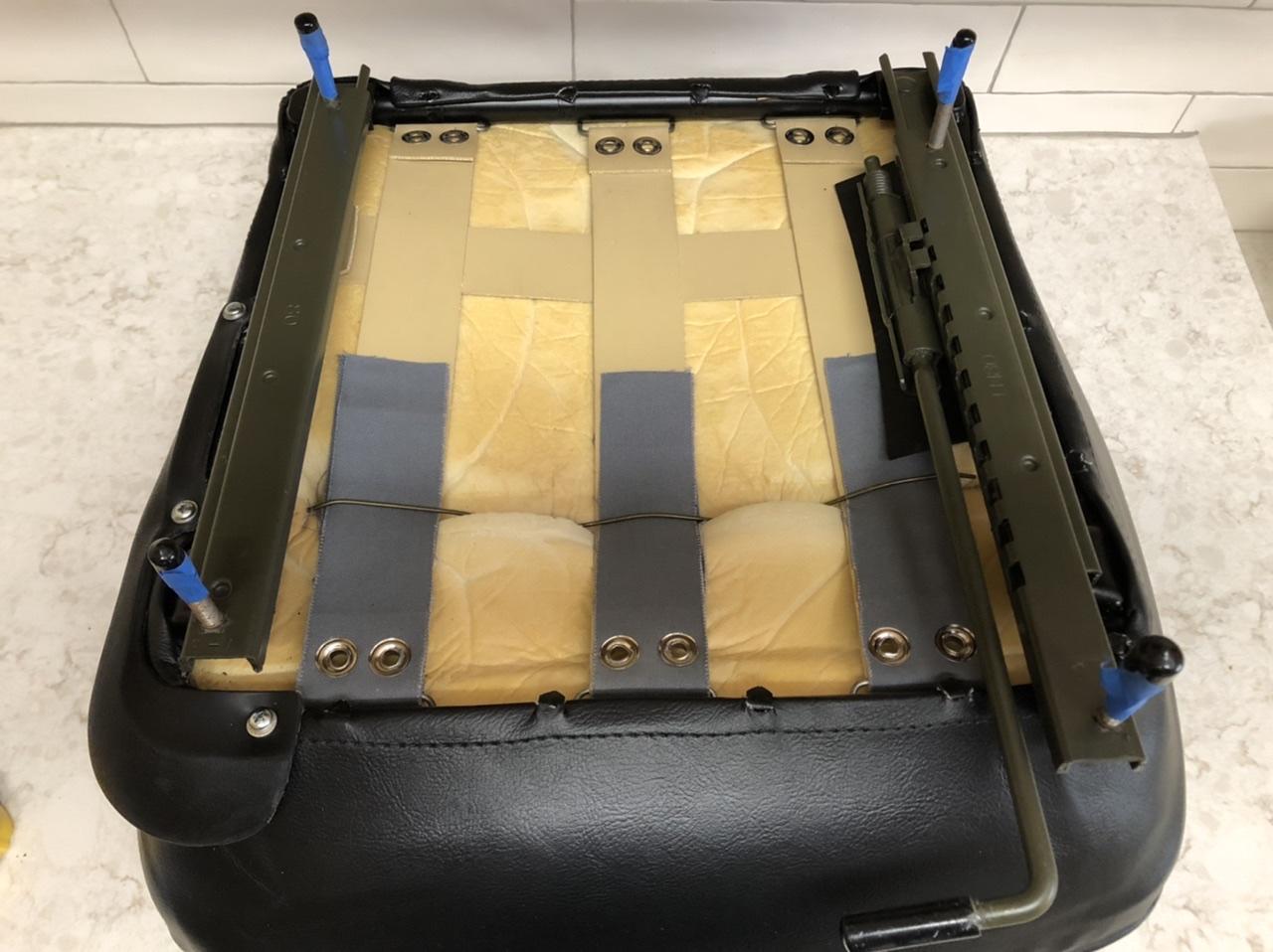
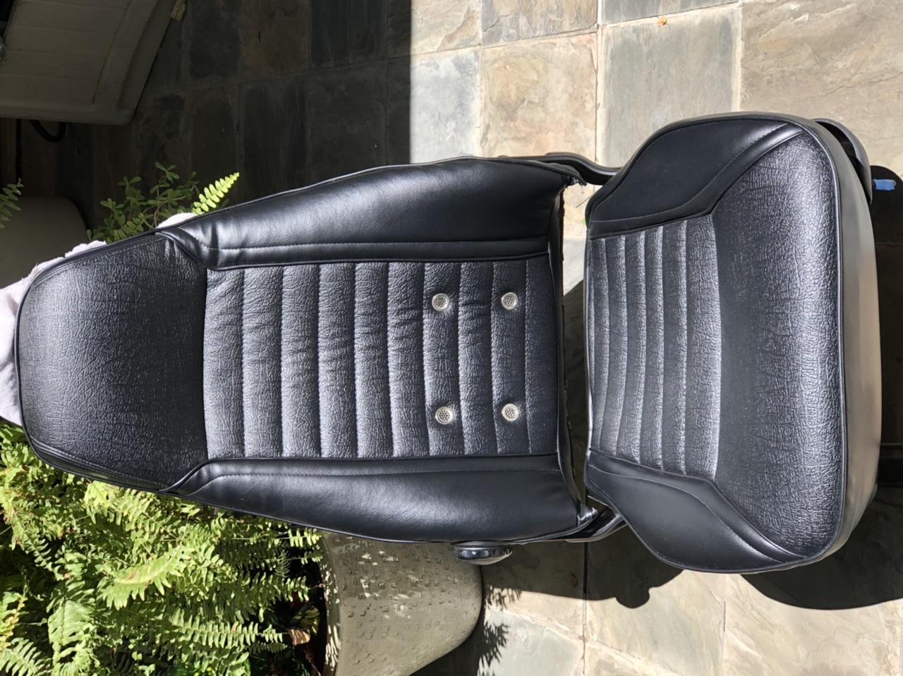
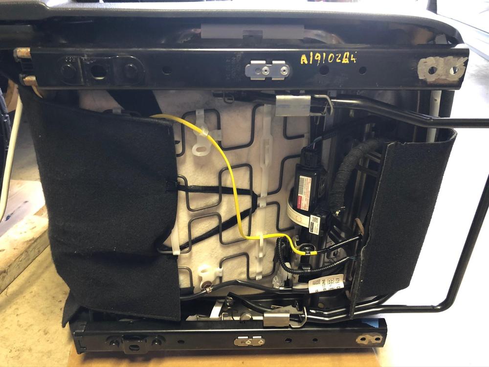
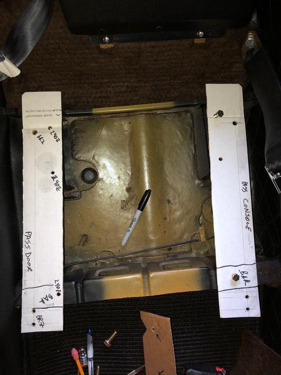
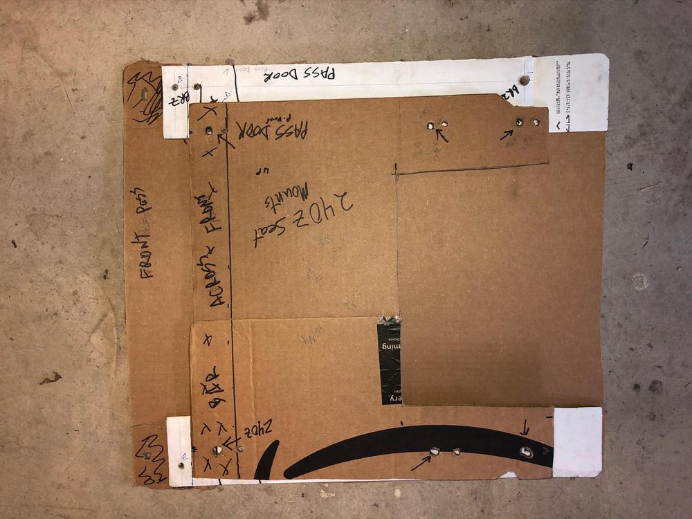
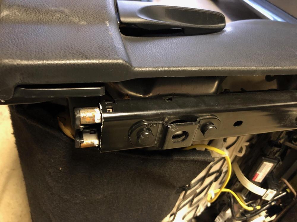
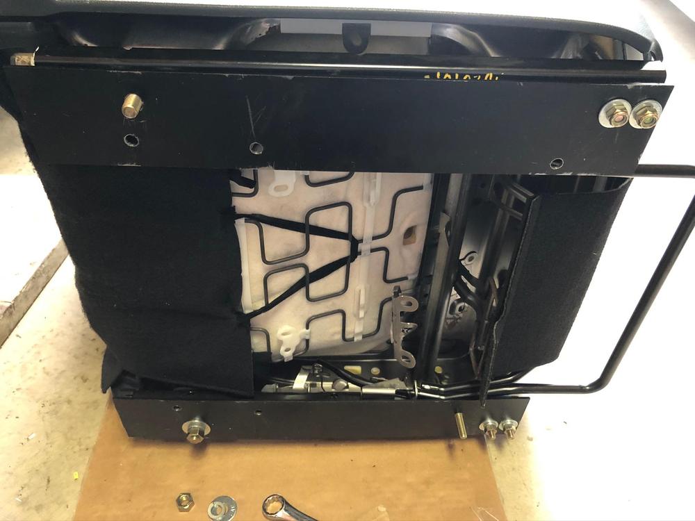
4 pointsEver since purchasing my 1970 240Z last April I found the refurbished seats lacking support. I searched for the recommended seats for swapping, but was unable to find any in both nice shape and reasonably priced. Purchasing locally appeared to be the only option due to shipping costs. In my research I found Miata owners using Subaru BRZ/Toyota 86/Scion FR-S seats and since Miata seats are popular swaps for 240Z’s, I decided to focus on the Subaru/Toyota seats. BRZ seat measurements: Seat: 19.5” wide x 19.5” long Hinge Width: 22” Seat Back Height: 33” During the research process I found a great post by Sean240Z from Feb 2013 that provided great how-to information. Before getting into the how-to details, here is my evaluation: Pro: Recaro-like; very comfortable; great side bolstering; seats recline; sturdy; drivers seat height adjustment; strap to keep shoulder harness in position; seat back release lever provides easier access to jack, tool boxes and rear deck. Con: Seats barely fit in Z car; loss of headroom; entry/exit; heavier than original seats; airbag. I’m 6’2”, 185 with 34” inseam and I fit comfortably. I must now lower my head more to get into the car. I think the max driver height is about 6’3” with the seat reclined. Installed Measurements: Driver Seat: Steering Wheel to Seat: 6” (vertical) Firewall to Seat Back: 48” Gas Pedal to Seat Back: 41” Steering Wheel to Seat Back: 18” Seat Bottom to Ceiling: 35.5” Reclined Seat Bottom to Ceiling: 37” Passenger Seat: Firewall to Seat Back: 45” Bottom of Glove Compartment to Seat Back: 31” The BRZ seats I found are black Alcantara with red stitching and leather trim from a low mileage wreck. They were priced at $200 each at an auto recycler, but they discounted them to $100 each. After a good cleaning, they are great looking seats. For installation I made four steel adaptor plates (1/8”x3”x18”). Steel purchased on eBay. Instructions: Remove original Z seat from passenger side; make U-shaped cardboard pattern of Z car mounting area and cut two 3”x18” pieces of cardboard to represent the steel adaptor plates. Mark orientation of cardboard to Z, such as passenger door side or console side. Cut off the two front “cat paw-like” portions of the BRZ seat mount. They extend too far forward and are not needed. Insert new seat into car to test fit; locate rear seat mount area to be trimmed on the Z car. Trim mount area until BRZ seat does not wobble and the adaptor plates lay flat. Paint the area trimmed so it does not rust. Determine slider position in relation to Z’s front mounting bracket and Z seat mounting holes; depending on the slider, there should be a slight exposure of the slider track rearward on the passenger door side only. Once installed, there is plenty of adjustment to slide the seat forward. Create cardboard pattern of entire BRZ seat, including slider mounting holes. Test fit in Z car and draw a line representing the front mounting bracket. Remove BRZ pattern; cut slider mounting holes and test by mounting the cardboard to the bottom of the seat using nuts and bolts. Place the Z cardboard pattern in original position; mark mounting holes and draw a line representing the front mounting bracket. Cut mounting holes and test by mounting on bottom of Z seat. Layout cardboard seat patterns, line up front mounting bracket line and determine best position for mounting holes on adaptor plates. Cut holes in adaptor plates and test fit in car; install Z mount bolt pattern, then adaptor plate patterns and finally BRZ seat pattern. Always better to test fit with cardboard than after drilling holes in the steel. Drill holes a little larger than needed, file off rough areas and test fit. If fit is good, clean up and paint adaptor plates to deter rust. Insert bolts through the front bolt holes to attach the adaptor plates to BRZ sliders. Note that sliders must move forward to access the mounting holes. Push sliders forward to mount rear slider bolts. Note the bolt closest to the door must be tightened when the seat is in the car. Place seat with plates attached into Z car. When the plates are attached to the Z car mounting brackets the bolt heads may interfere with sliding the seat. If so, then loosen BRZ mounting bolts and insert washers between slider and adaptor plate to raise the slider and clear the bolts going into the Z’s seat mounting holes. Another option is to use carriage bolts with flat heads. The BRZ seat hinge area fits very tight, so ensure that the seat belt buckle is visible. If not, it is almost impossible to access it later. After completing the passenger side, repeat on the driver’s side. Cardboard patterns can be flipped over and reused, but make sure the holes are marked to avoid confusion. Good luck with your install!


 4 points
 -
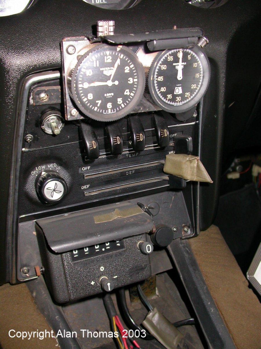
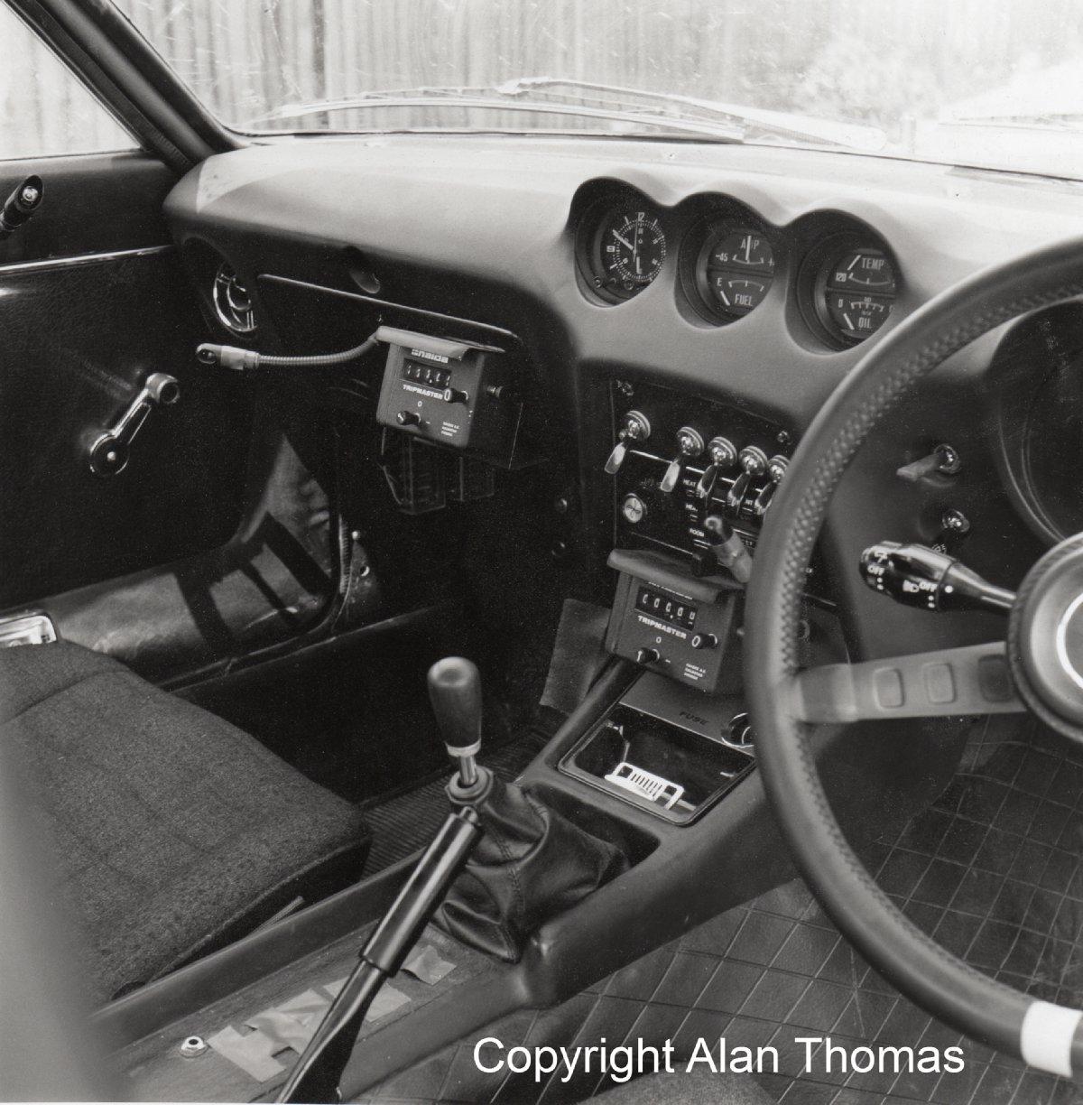
3 pointsFor timekeeping, the usual 'Works' kit was a pair of HEUER (pre-TAG) clocks: A 'Master-Time' 8 day clock and a 'Monte-Carlo' stopwatch. Some of the more serious navigators would have their own preferred/maintained sets, and positioning/mounting was also subject to individual navigator preference whenever changes were possible before an event. The usual HEUER Master-Time & Monte-Carlo pair was quite expensive at the time (they still are...) and very tempting for a thief when the cars were in Parc Ferme. There are stories of some sets going missing... For distance measuring, the usual Works kit was a pair of HALDA Tripmasters connected individually to the front wheels by drive cables which ran through the centre of each hub spindle, exiting the hub casting at the back of the strut via a hard tube. Having two Halda drives operating individually allowed the navigator to take an average for increased accuracy. Positioning of the Haldas on the dash varied somewhat according to RHD or LHD layouts and feedback from navigators about their own preferences. On later Works 240Zs and 260Z, Halda Twinmasters were fitted for doubling-up on accuracy. As can be seen, the early Works cars were usually fitted with the oscillator-driven Kanto Seiki 'Rally' stopwatch clocks too. Nothing made by SEIKO for these cars.

 3 points
 -
2 points
-
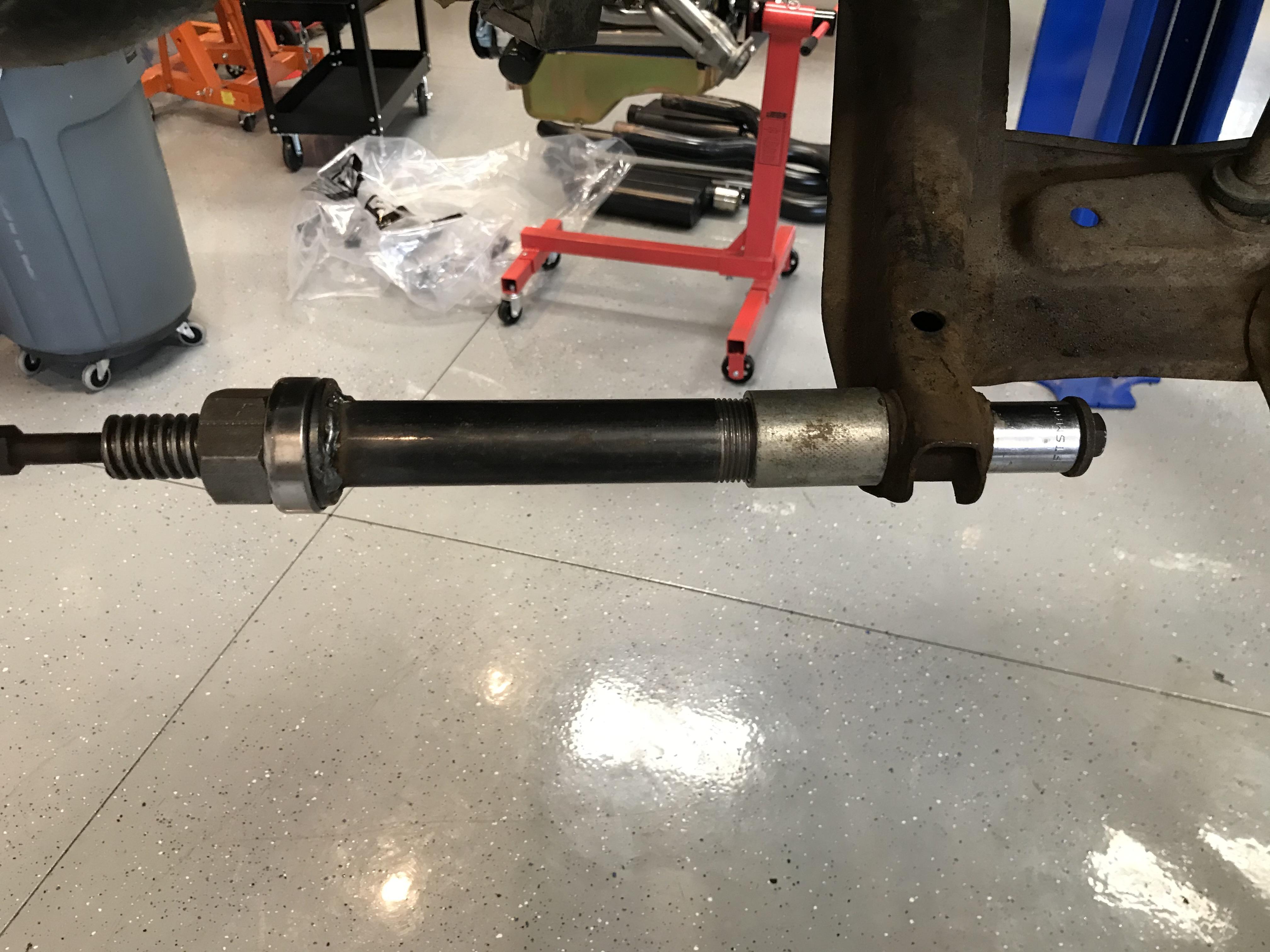
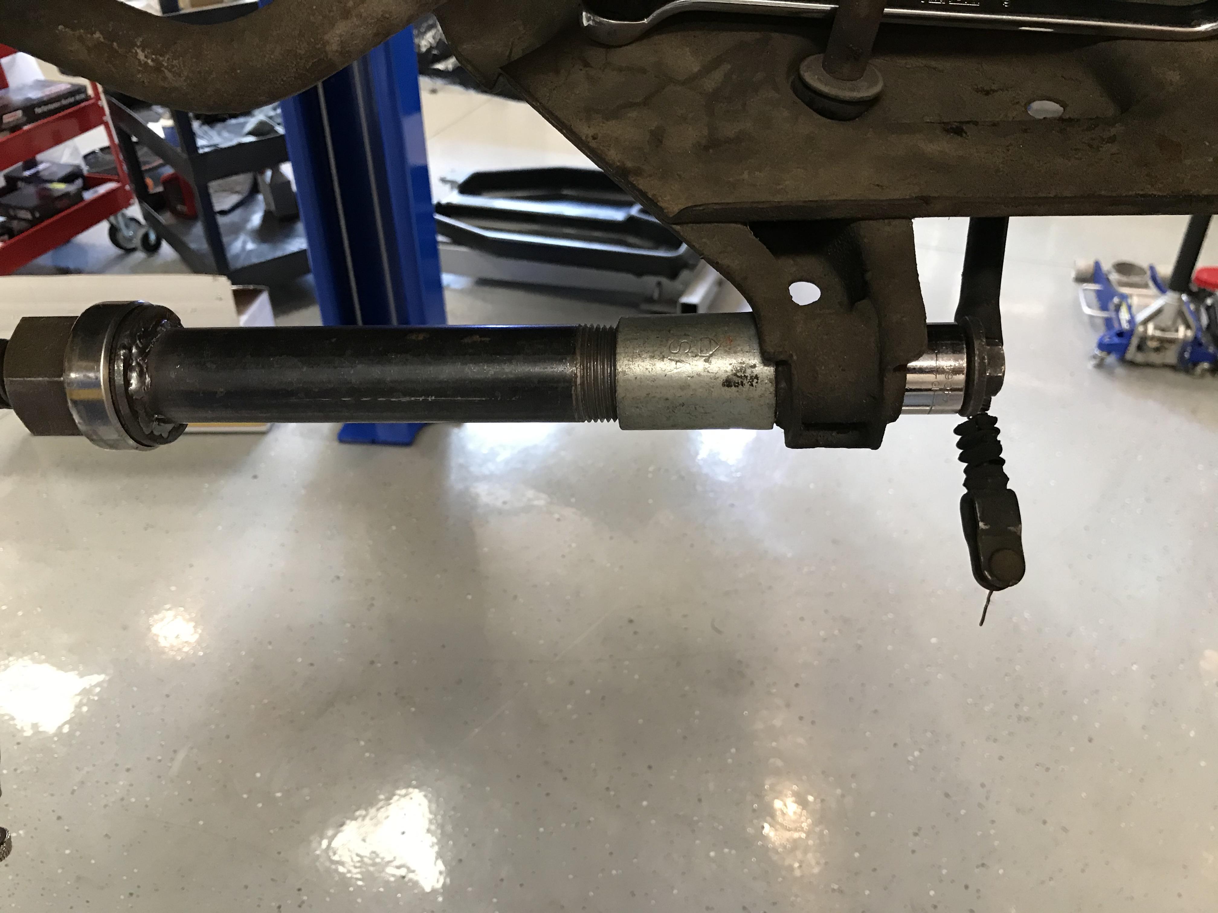
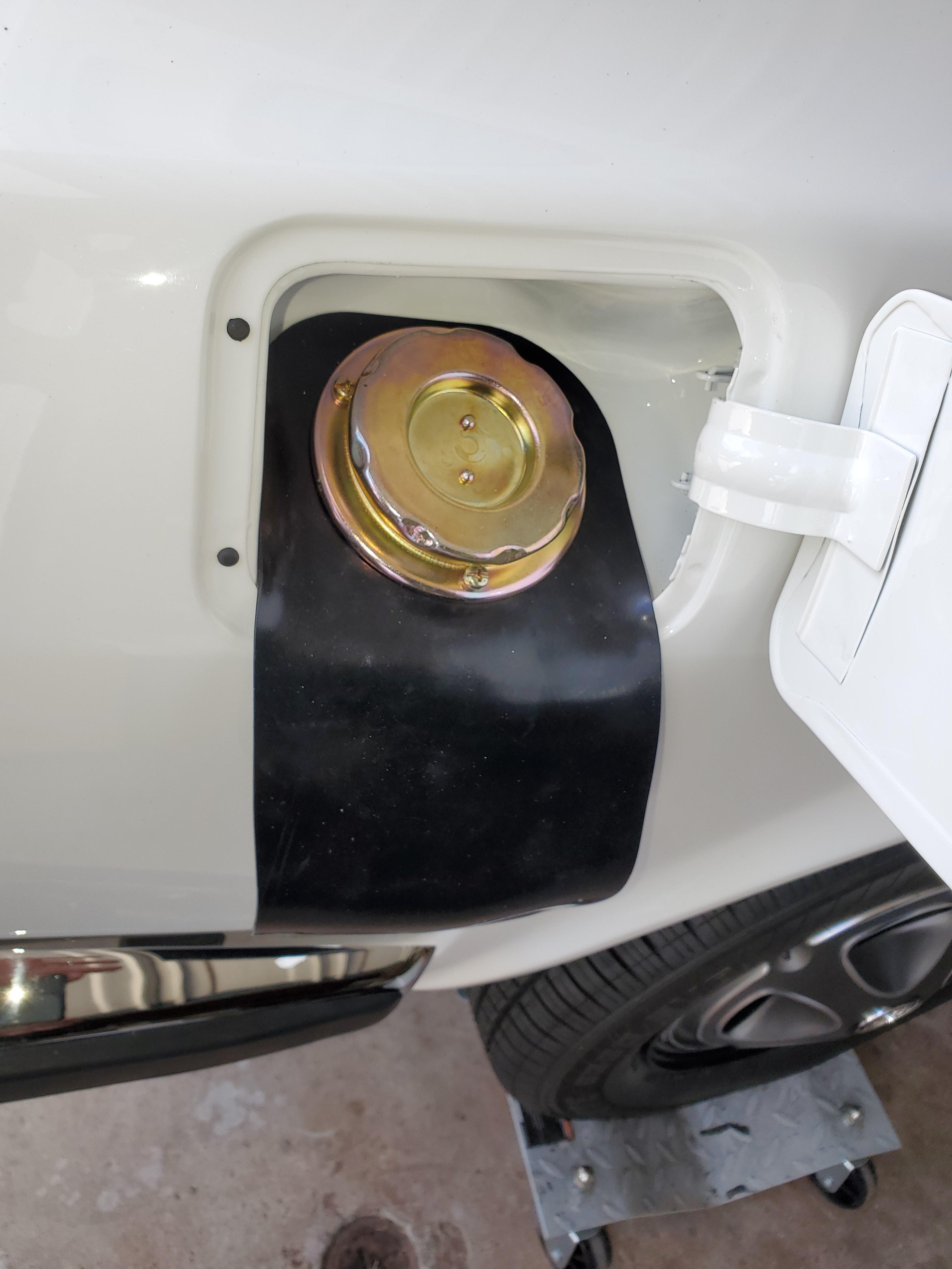
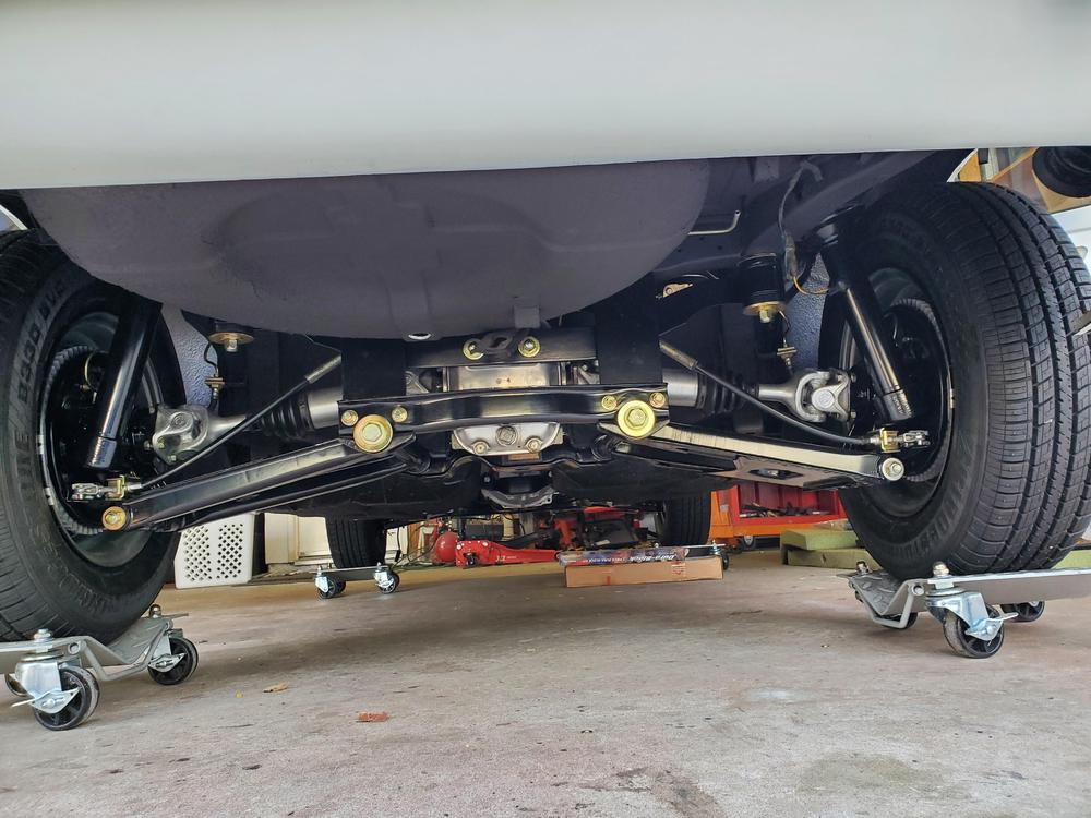
1 pointUpdate: I removed the four OE bushings yesterday using my modified spindle pin puller. I used a bolt and washer through the socket that threaded into the puller rod rather than using the spindle pin. Overall, the puller worked well, but I did learn a few things. First, unlike pulling a spindle pin, the puller rod must be held and not allowed to rotate. I used vice grips to hold the puller rod, but I will likely either weld a nut on it or machine two flats on it. I had to use a propane torch to ease the control arm grip on the bushings. Three came out really well, but one kept cocking the socket due to the thin wall on the OE bushing. I then grabbed a socket that only picked up the center sleeve rather than the outer sleeve and the bushing pulled right out. I thought for sure that the rubber would separate, but it held together just fine. In the end, I got all four out using my spindle pin puller tool which was a win. I didn't have to remove the arms from the car or struggle with a press and risk bending the arms. Since I'm installing poly, I won't be able to say if the tool would pull new ones in, but I would think it would with no issue.

 1 point
 -
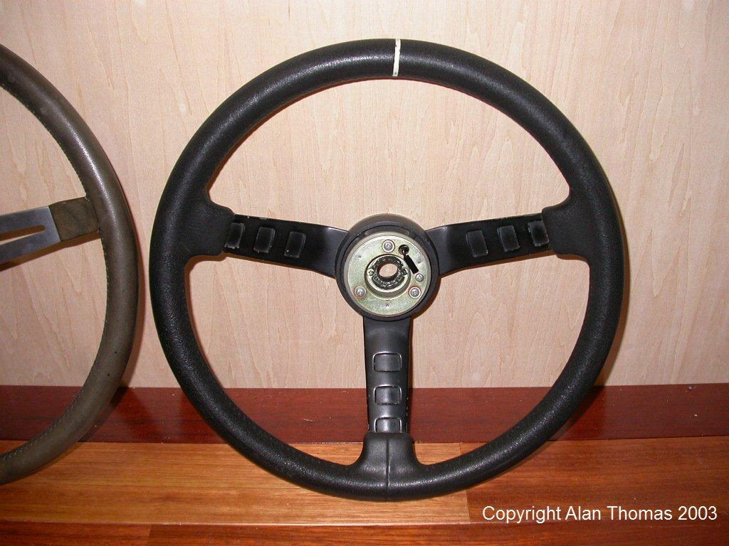
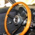
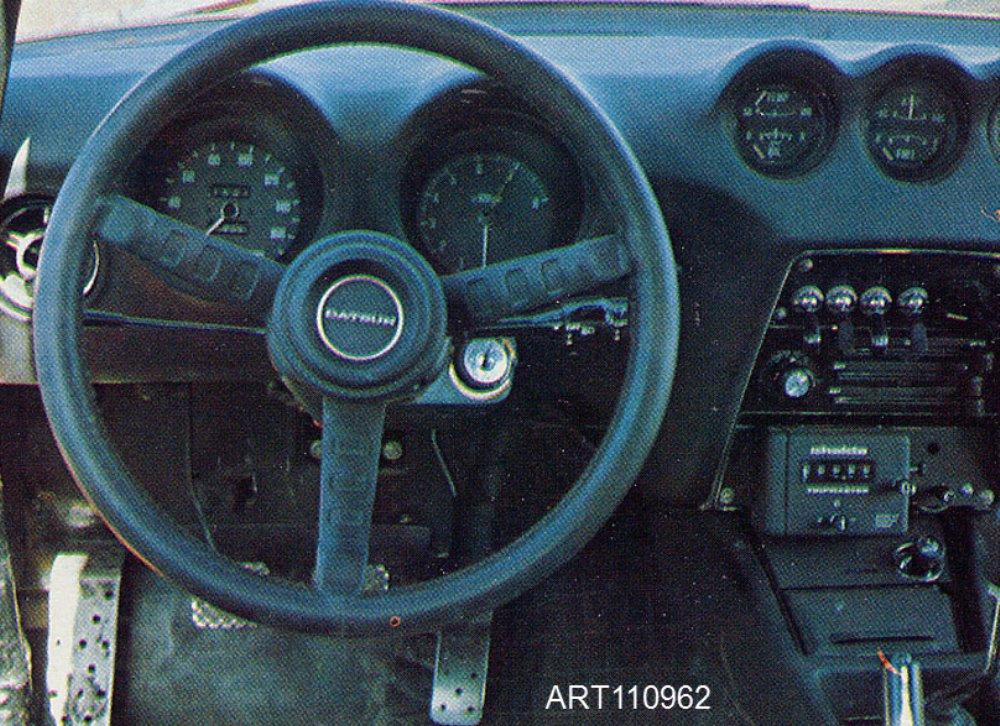
1 pointIts an early Nissan Works version of the 'Datsun Compe' urethane-grip steering wheel made by Izumi. The Works version was a larger diameter version of the Compe, and followed the same solid-spoke to perforated-spoke transition as seen in the OEM S30-series Z Izumi steering wheels.
 1 point
 -
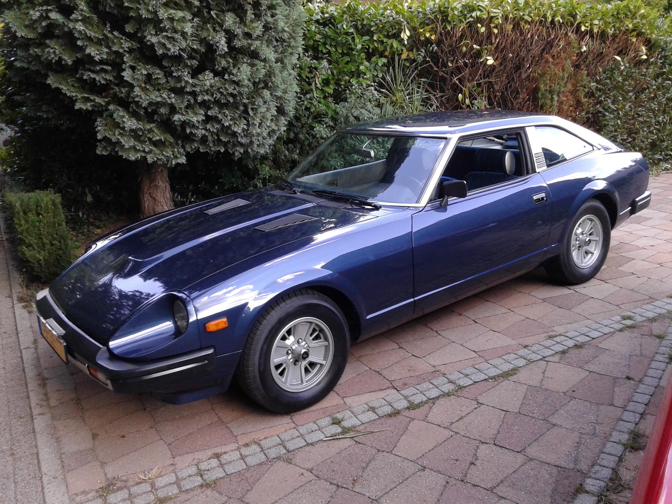
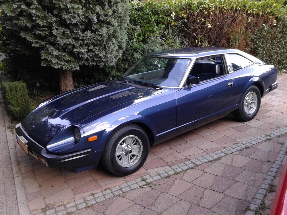
1 pointVery nice 280zx.. almost as beautiful as mine.... just kidding.. it's all nice. just wanted to say this ad needs some bigger pics please like this for example.. Could you also put in a (detail) pic from the wheels? Thanks! ALSO 16000 DOLLARS FOR A 280ZX WITH THAT KIND OF LOW MILES ON THE CLOCK IS MAKING ME SICK.. I HAD TWICE AS MUCH TO INVEST IN MINE WITH 119000 KM IS: 73958 MILES This car is sold in a jiffy... No this one is not for sale... just an example pic.. (everything is buyable they say.. at 35000 euro's i start thinking of (maybe) selling it.. just that one knows where the "border"lays.. ? ) My beautiful euro version 2+2 (With my length i can't sit in those 2 seater seats.. my head is against the roof... seriously!!!!)
 1 point
 -
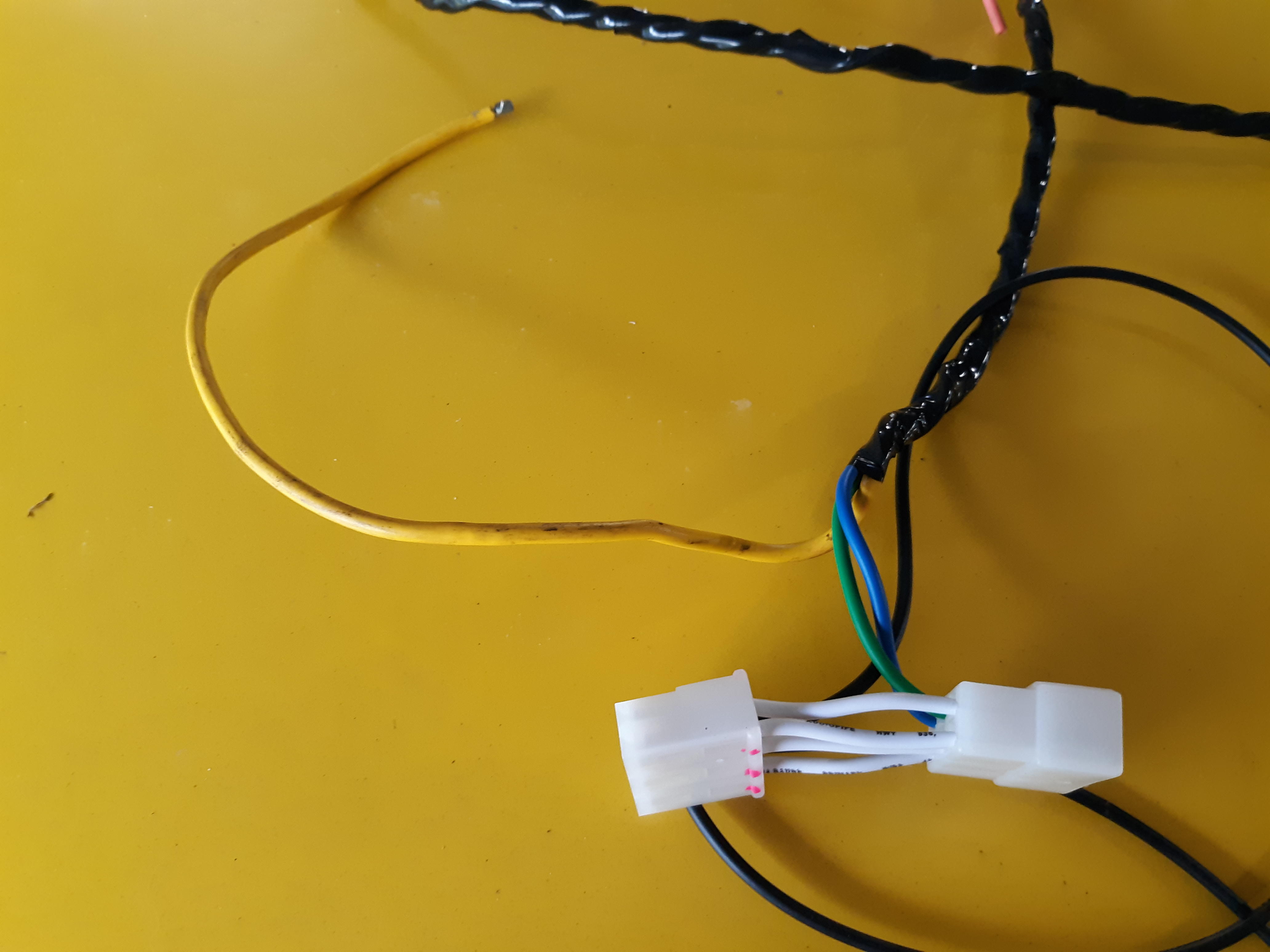
1 pointThanks for checking! And even if you do find the mate for the 240 version, that won't work for me. They need to be 260 or later. Here's to hoping I can turn something up. Kicking myself for not grabbing a set before the pandemic started. I had a couple options for a pair for under a hundred bucks and didn't get to it.1 point
-
1 point
-
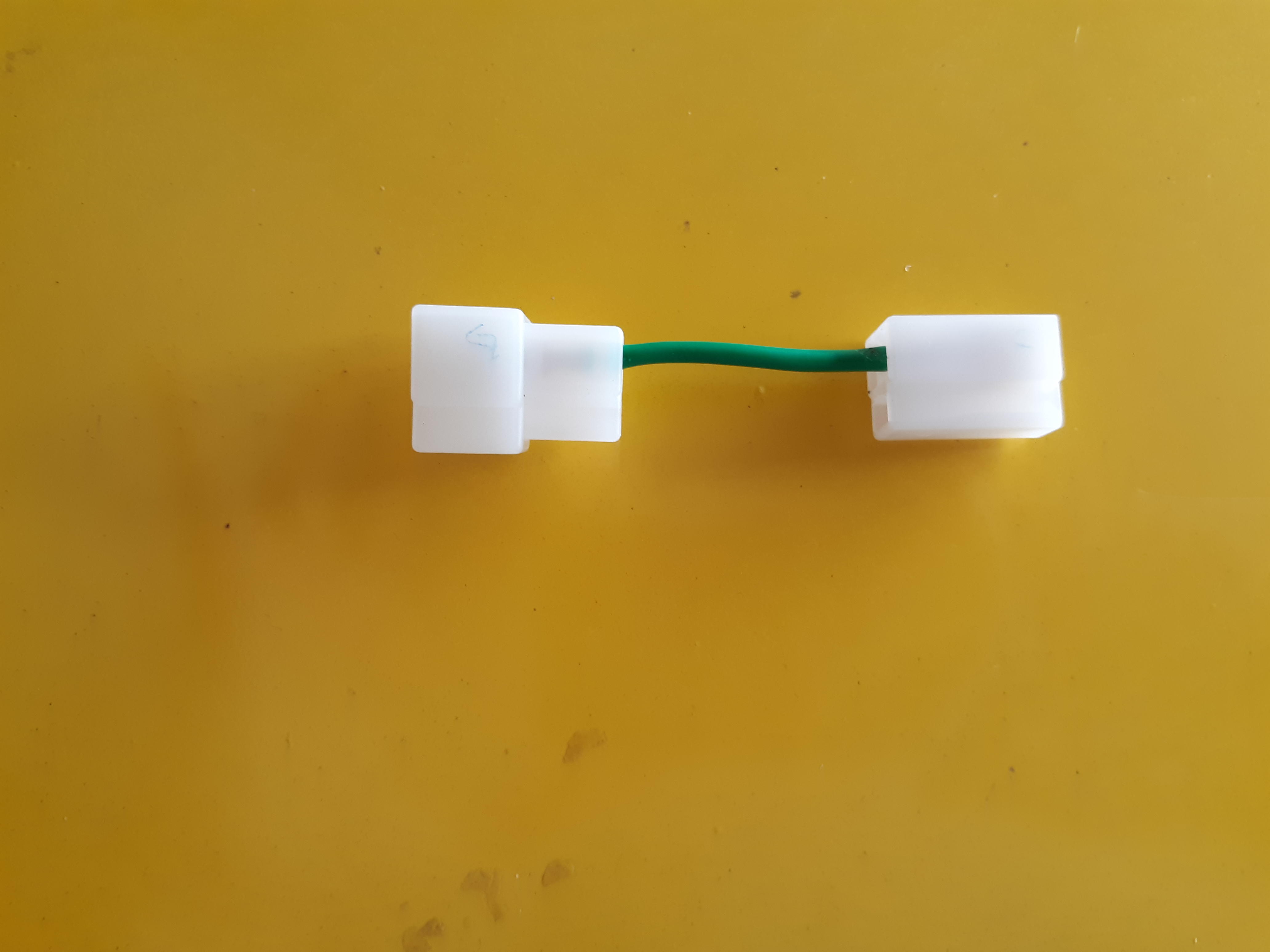
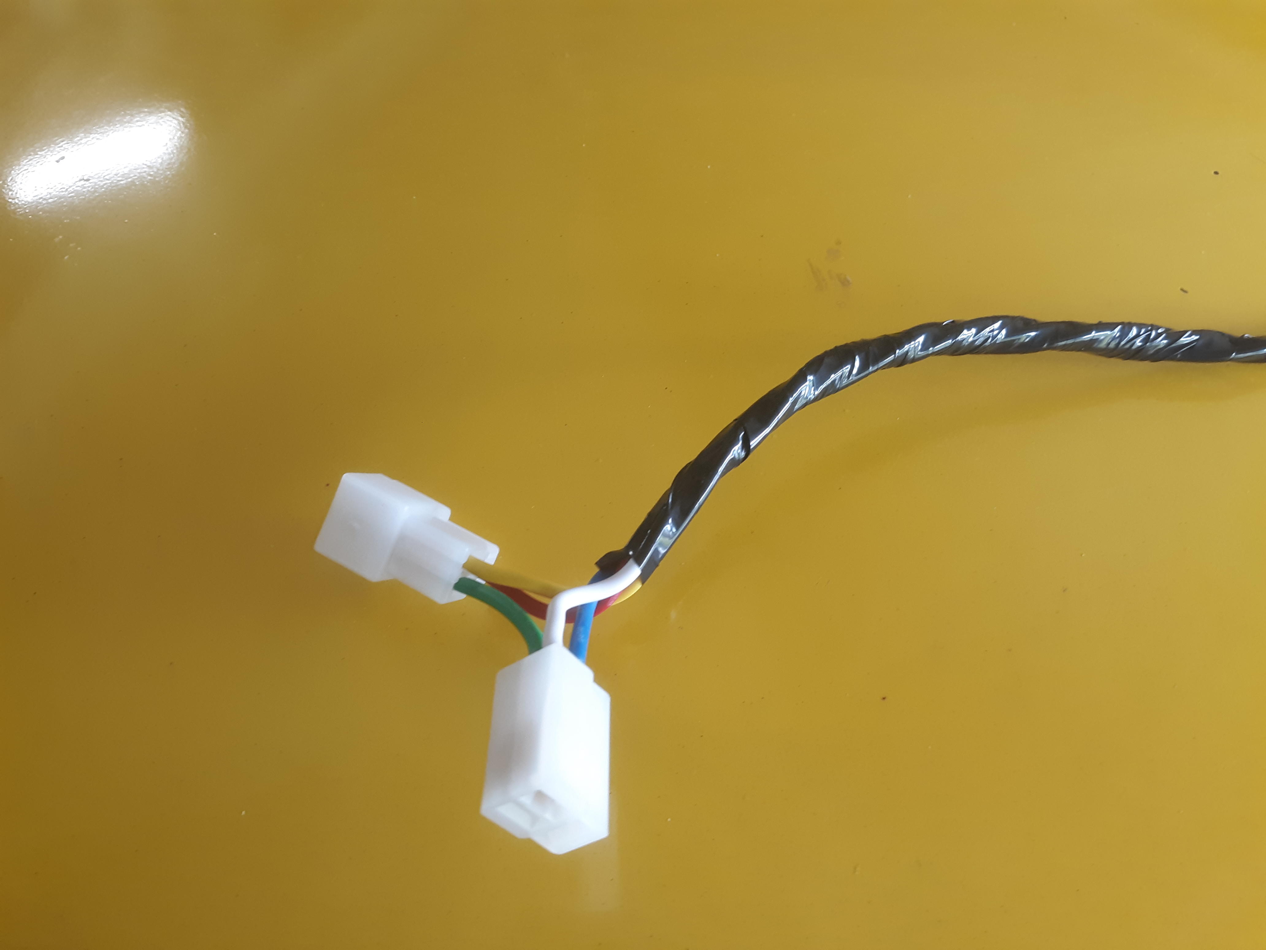
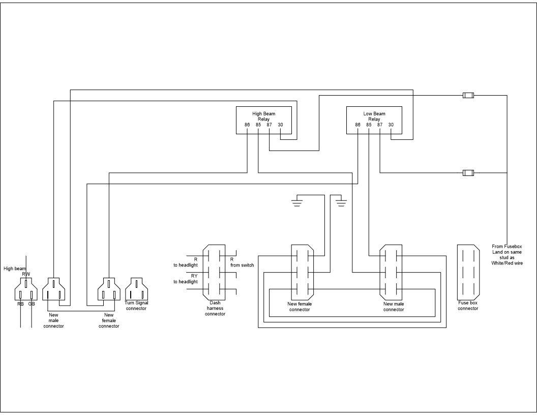
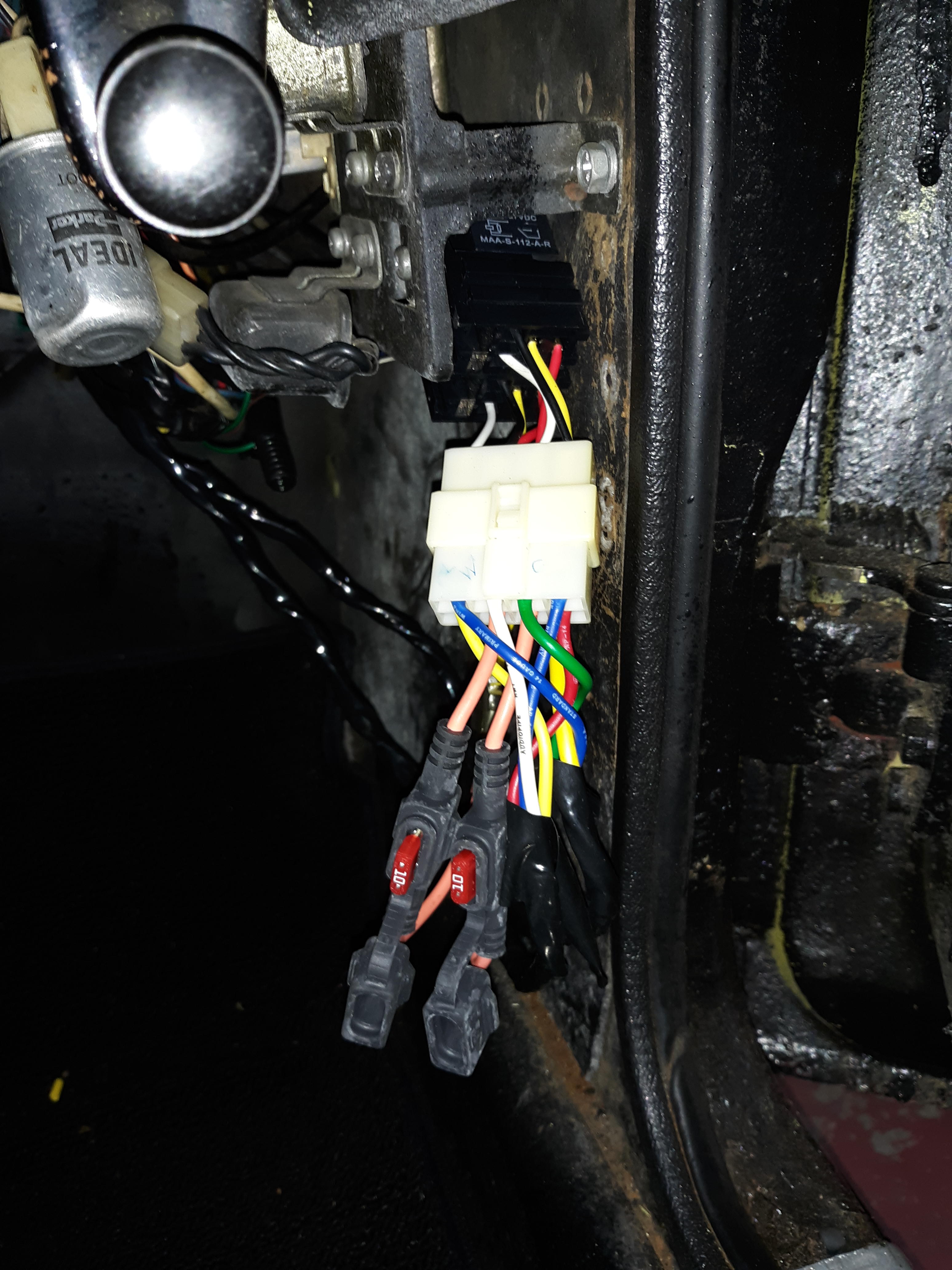
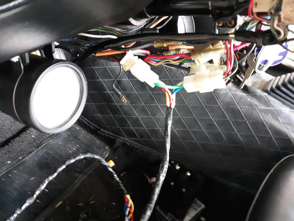
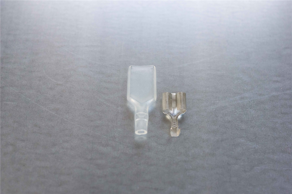
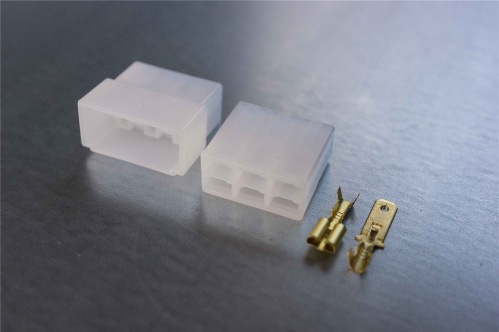
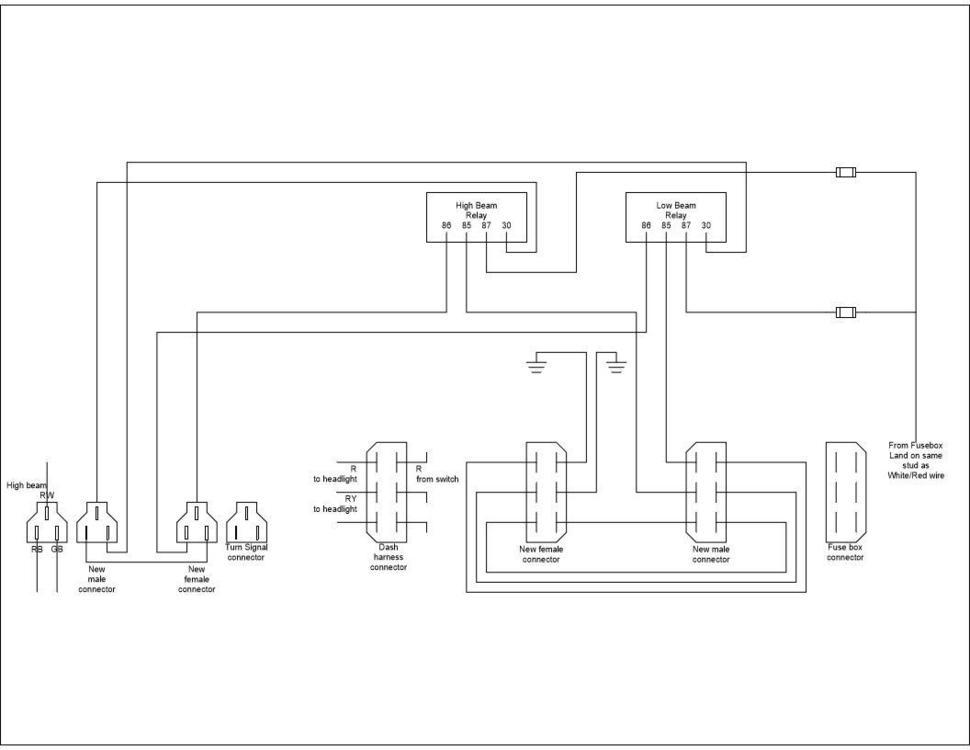
Here is a DIY headlight relay modification that I implemented on a friend's 73 this weekend. This will not work on early Z cars where the headlight switch completed the path to ground. Parts needed: 2 SPDT or SPST automotive relays with bases 14 AWG wire - It is good to have many different colors to keep things straight 12 AWG wire Electrical tape to wrap your wire bundles 1 3-pin 6.3mm non-latching connector (male and female) 1 6-pin 6.3mm non-latching connector (male and female) 2 4mm bullet terminals with insulators and 1 4mm dual socket terminal with insulator 2 inline fuse holders with 10A fuses 2 5A glass fuses 1 yellow ring terminal (solderless lug) (BTW I'm guessing on the size. I can't remember for sure) 2 blue ring terminals (solderless lug) Steps Remove the negative battery cable Remove the clamshell cover on the steering column Remove the center console and loosen the fuse box for access underneath Figure out where you can mount the relays. If you can get relay bases with mounts built in, that is preferred. Estimate the distance from the turn signal connector to the relays and from the fuse box to the relays Cut four lengths of 14 AWG wire for the run from the turn signal connector to the relays and wrap the wires together Cut a short jumper wire to run between the 3-pin male and female connectors per the drawing Note which wire you plan on landing on the connectors Crimp the pins onto the wires and insert them into the connectors Break apart the 3-pin turn signal connector and plug your new connectors into the turn signal connector in the steering column Route the new wire down the steering column and over to where the relays will be mounted. Break apart the 6-pin connector at the fuse box that has 2 red and 1 red/yellow wire. Cut 2 14 AWG wires to run from the fuse box to the relays. Cut two shorter runs of 14 AWG wire (I prefer black) for the grounds. Cut a length of 12 AWG to run from the fuse box to the relays. Cut 4 short 14 AWG jumpers to go between the male and female 6 pin connector. Wrap the 12 AWG with the 2 long 14 AWG wires. Leave enough length of 12 AWG wire to route into position Crimp pins to the wires and insert them into the appropriate connectors. Route the 12 AWG through the underside of the fuse box and attach the yellow ring terminal. Lift the rubber boot covering the terminal on the white/red wire on the underside of the fuse box. Remove the screw, and add the new ring terminal on the screw with the white/red wire. Secure the screw back onto the fuse box and cover with the rubber boot. Secure the fusebox to the car. Connect the jumper harness into the fuse box connectors. Route the ground wires over to a screw. Trim the length of the wires if necessary. Attach the blue ring terminals and secure the ground wires to the car. Route the 3 wire bundle over to the relays. Trim the length of the wires if necessary. Attach the 4mm dual socket terminal to the 12 AWG wire. Attach 1 4 mm bullet terminal to each inline fuseholder. Attach the fuseholders to the 12 AWG wire. You can do one of two things at this point. You can remove the existing wires from the relay bases and use 6.3 mm female terminals on the new wires, or you can use an 8-pin 6.33 non-latching connector to connect the relay bases to the new wires. Make the connections per the attached schematic. Change the headlight fuses in the fuse box to 5A. Attach the negative to battery. Test your headlight relays by turning on the headlight switch and alternating between high beam and low beam. Once you verify relay operation, install 10A fuses in the inline fuseholders. Replace the center console and clamshell. Here is the schematic: This reverses the original design to have 2 positive wires going to the headlights and 1 negative. This allows the use of LED headlights.


 1 point
 -
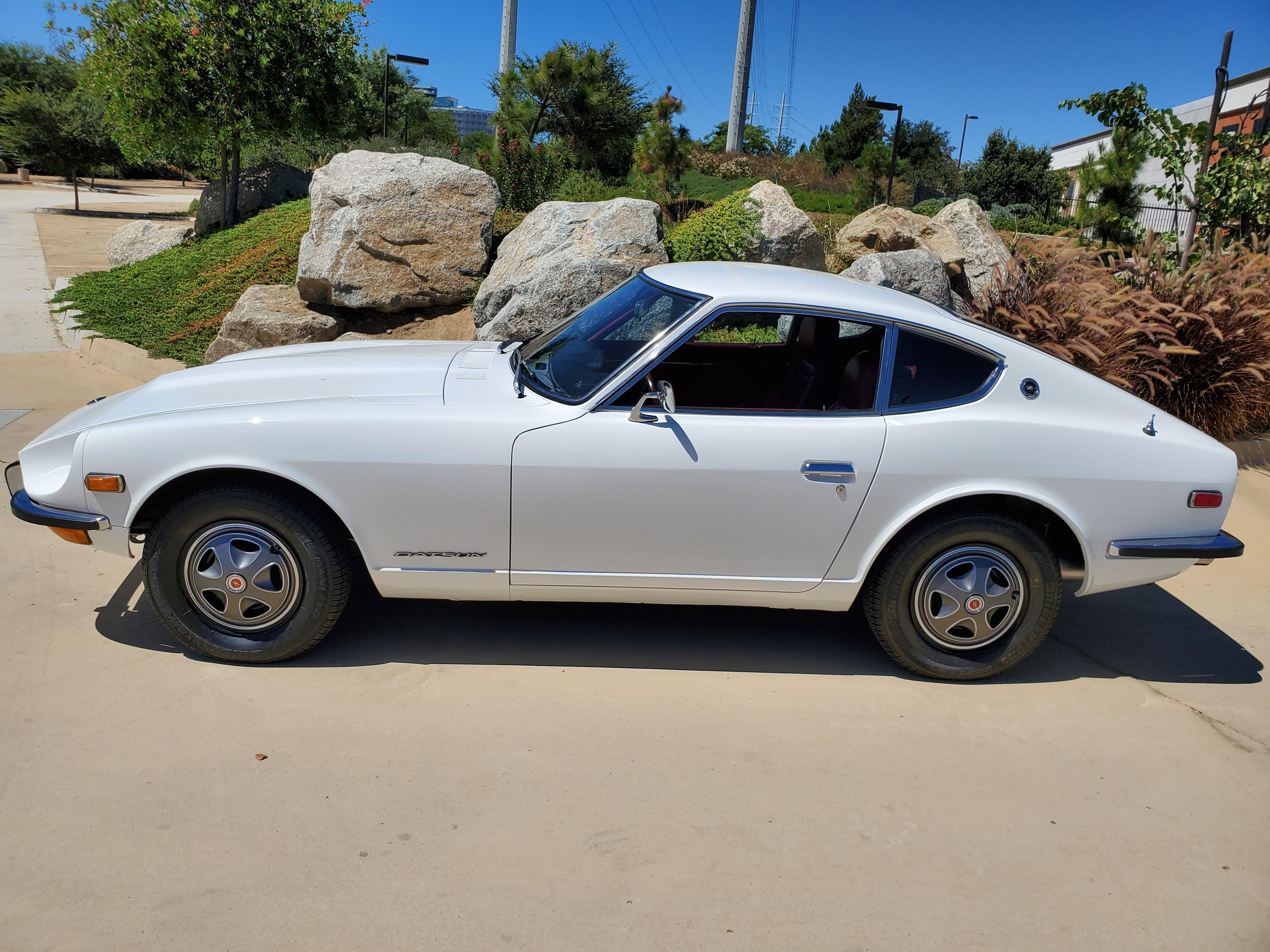
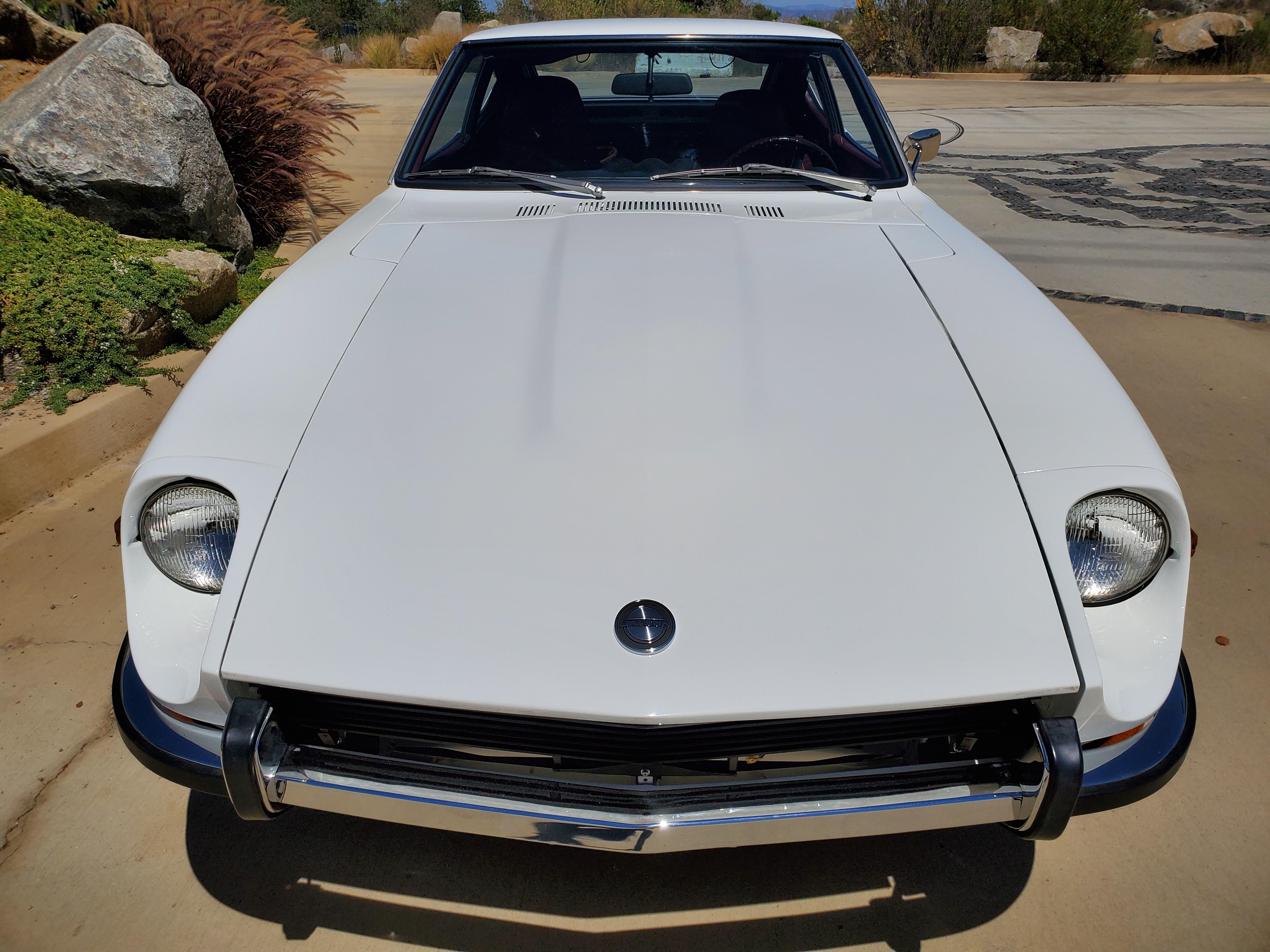
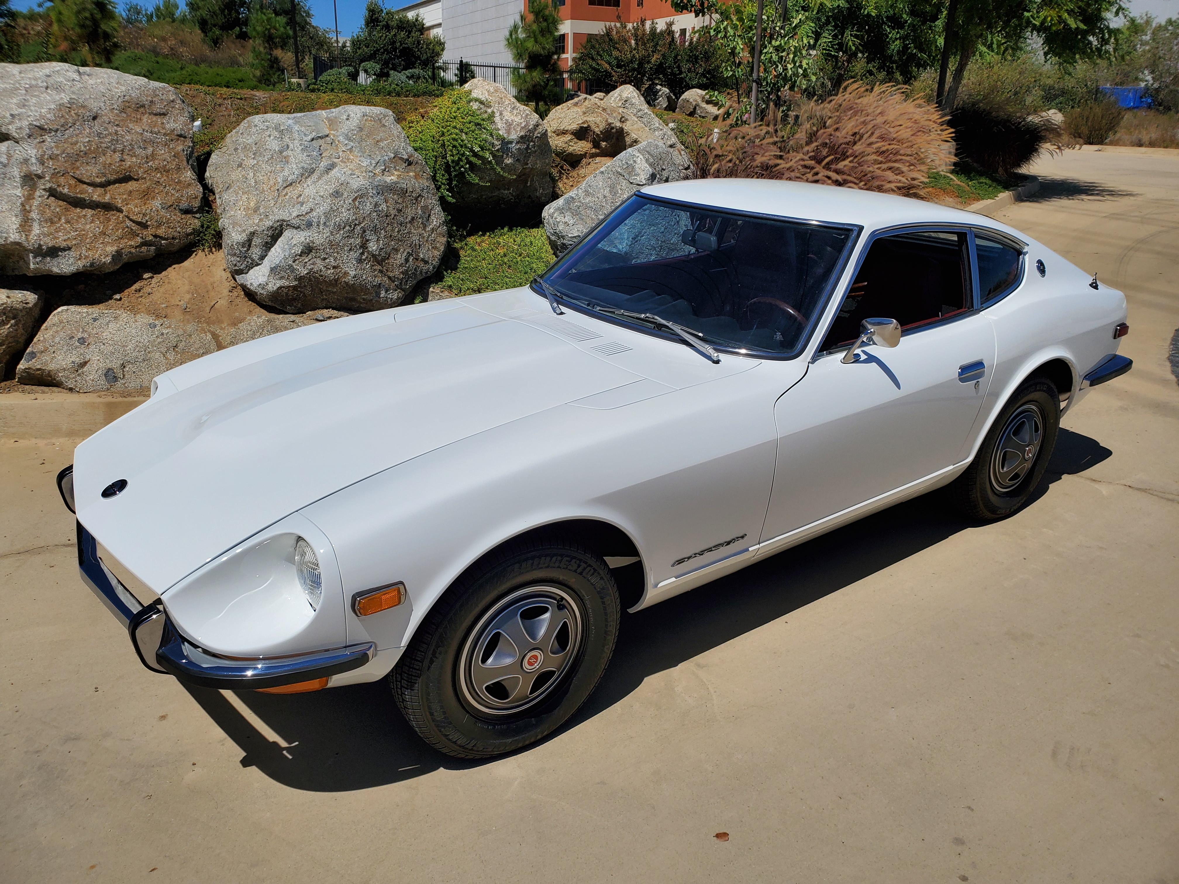
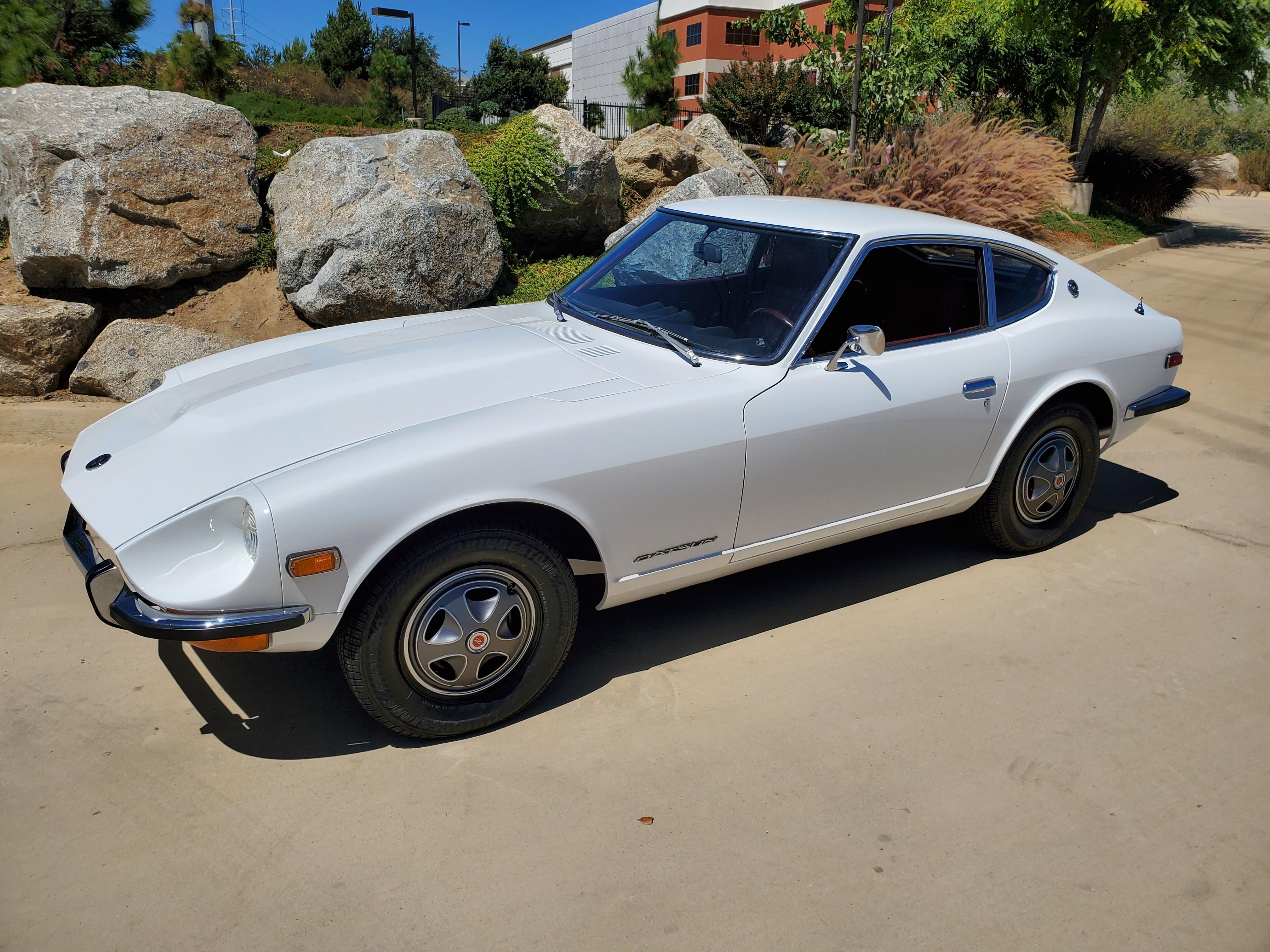
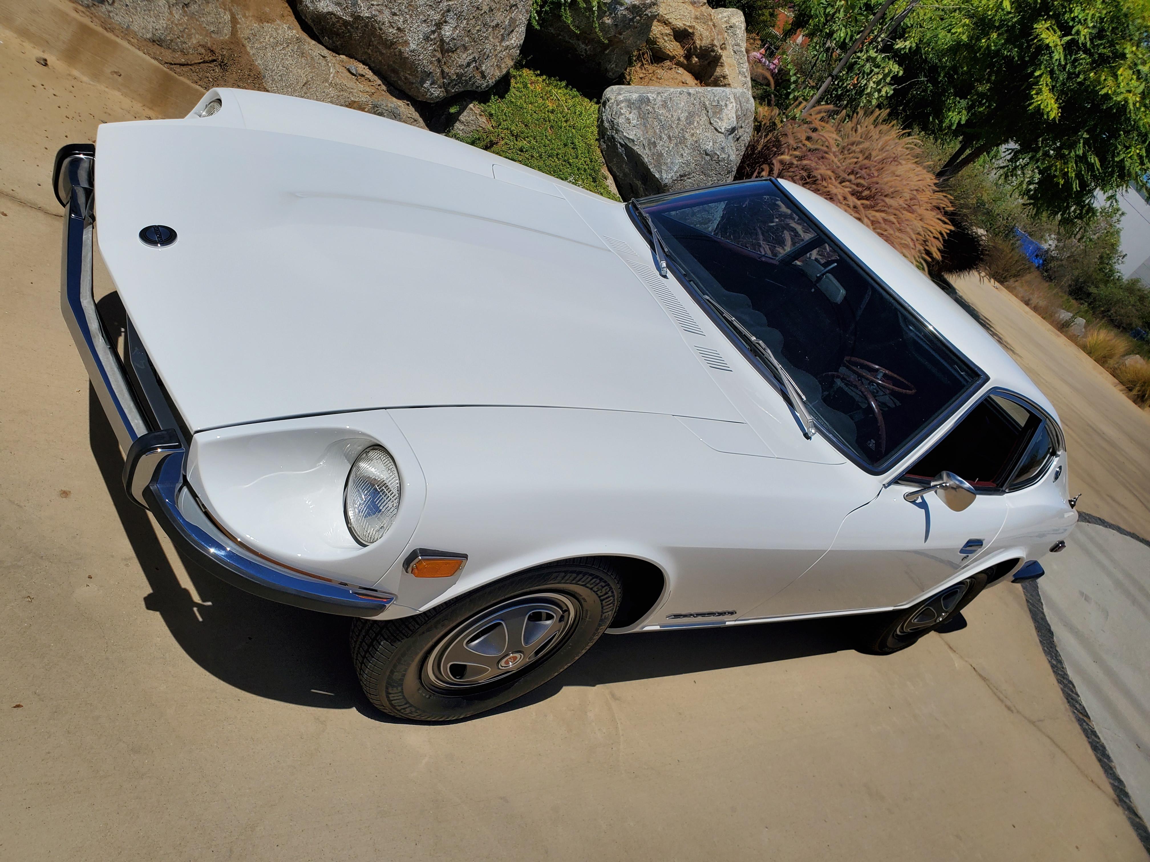
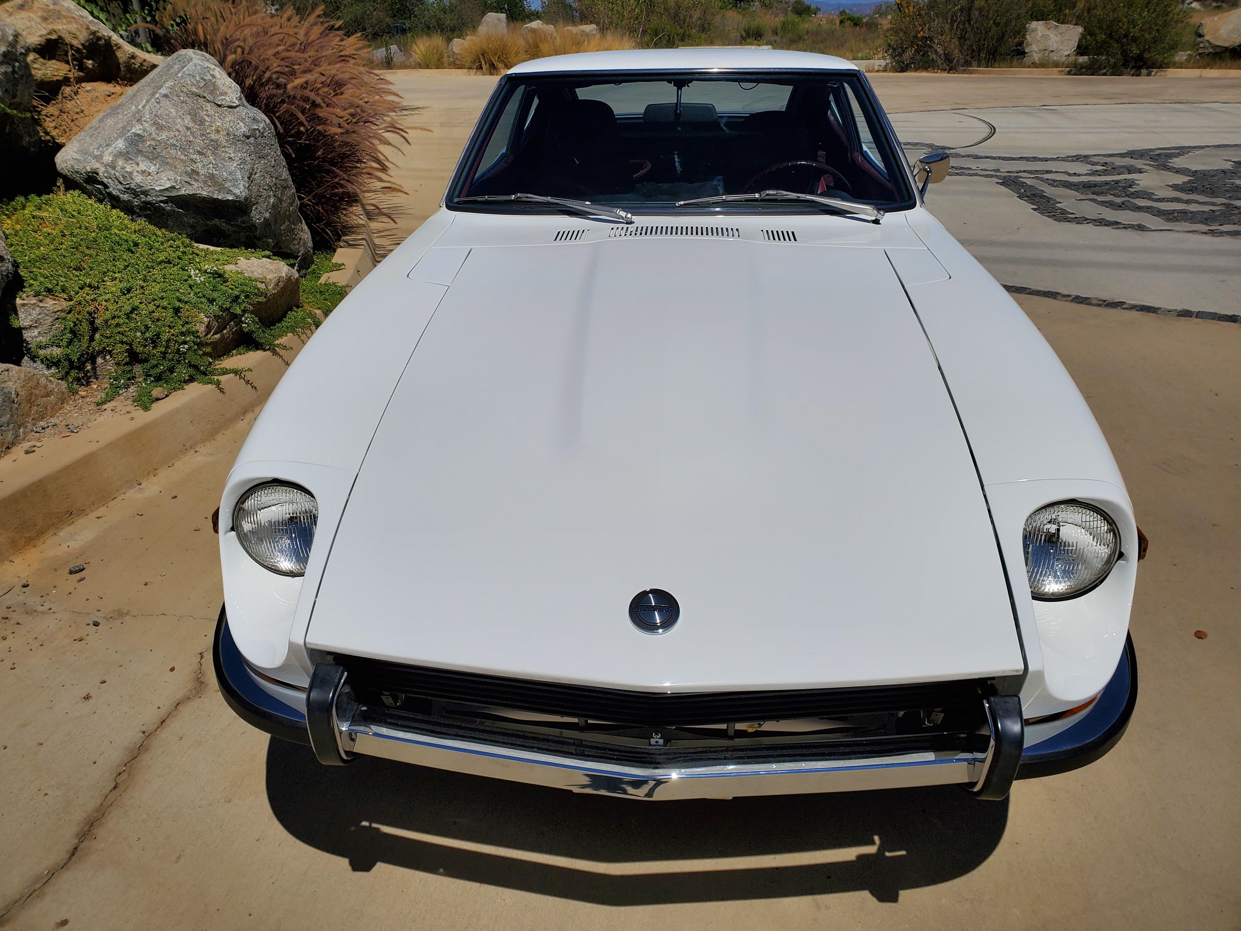
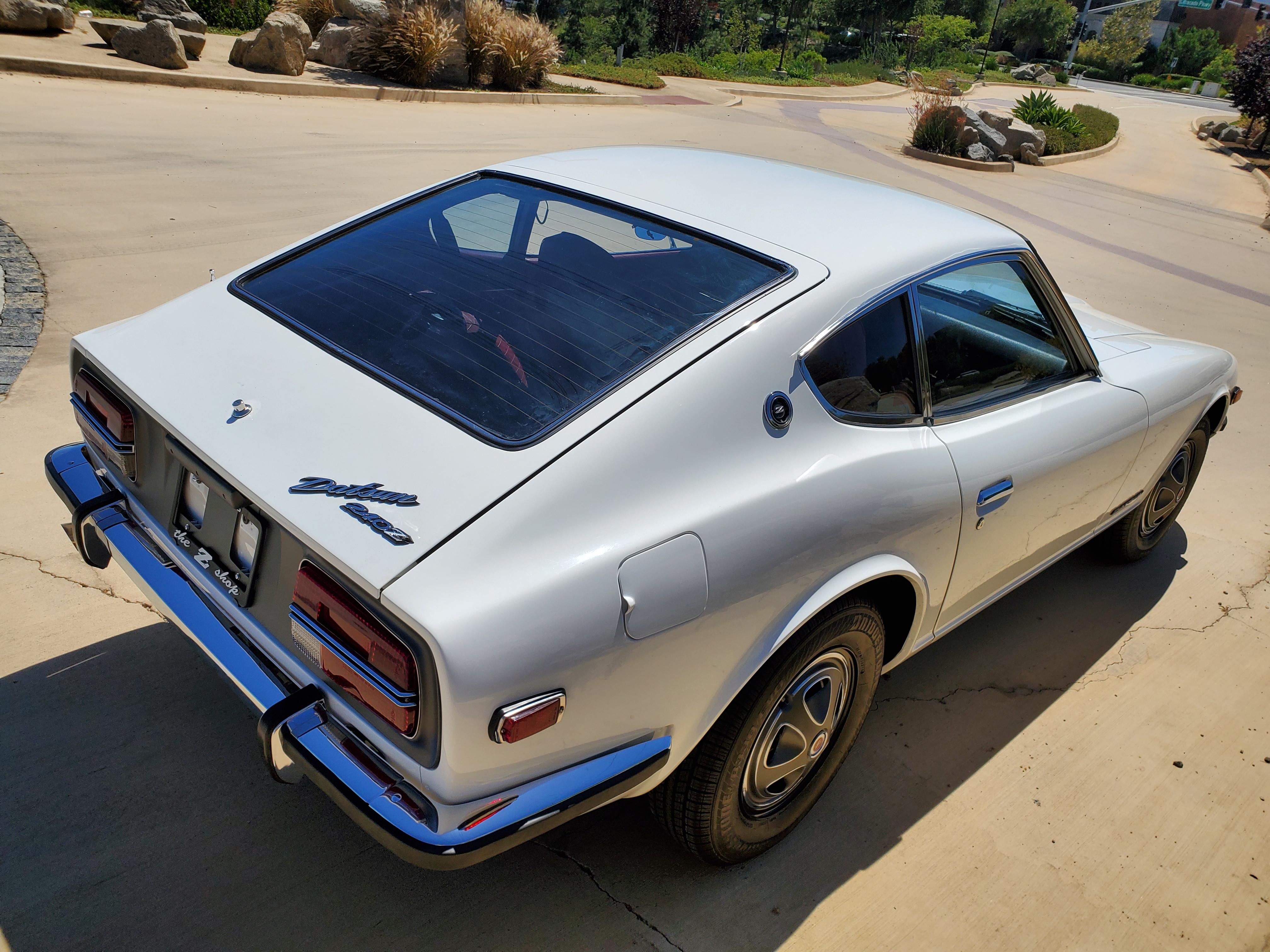
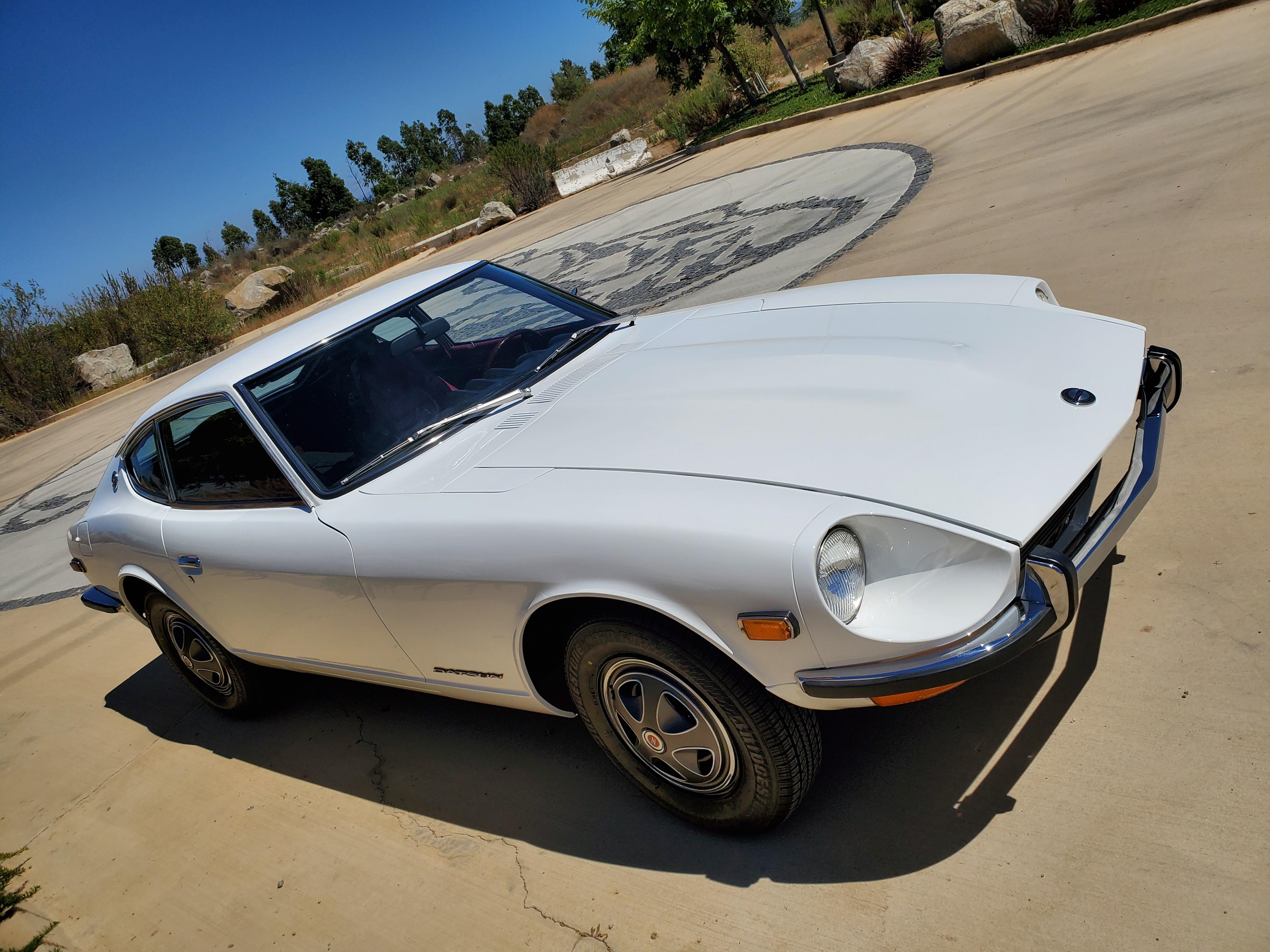
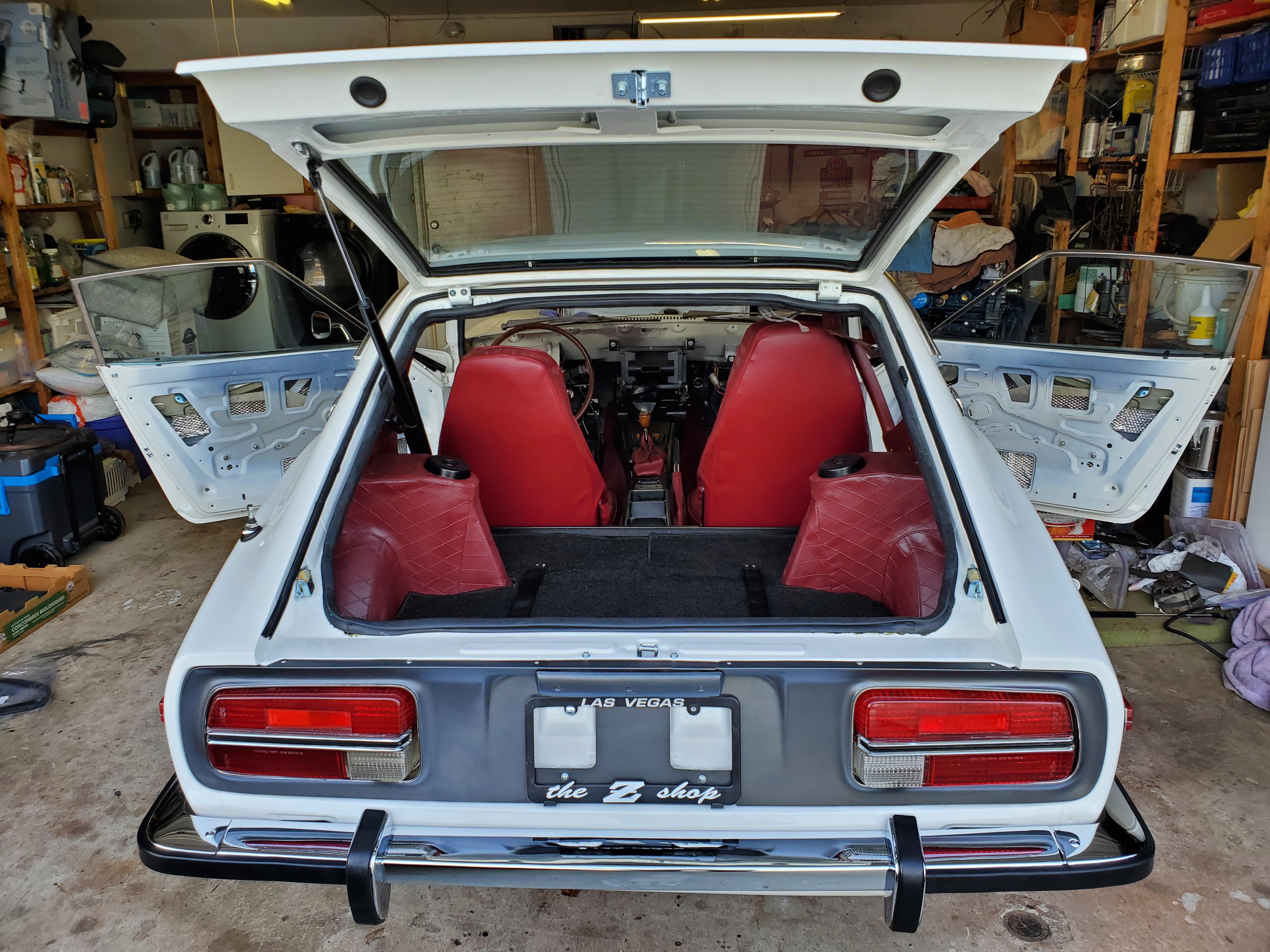
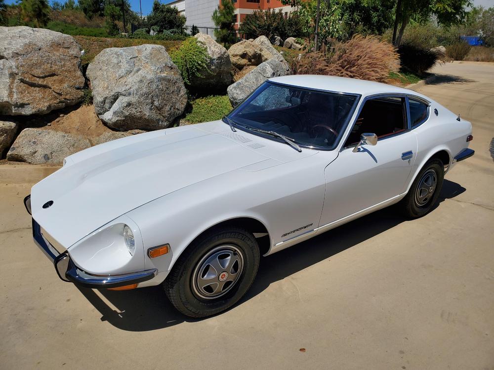
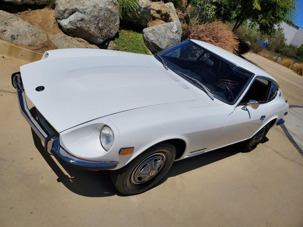
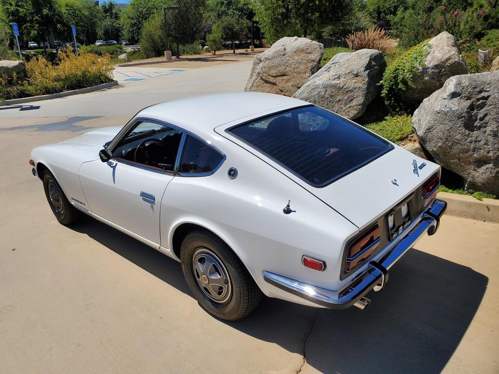
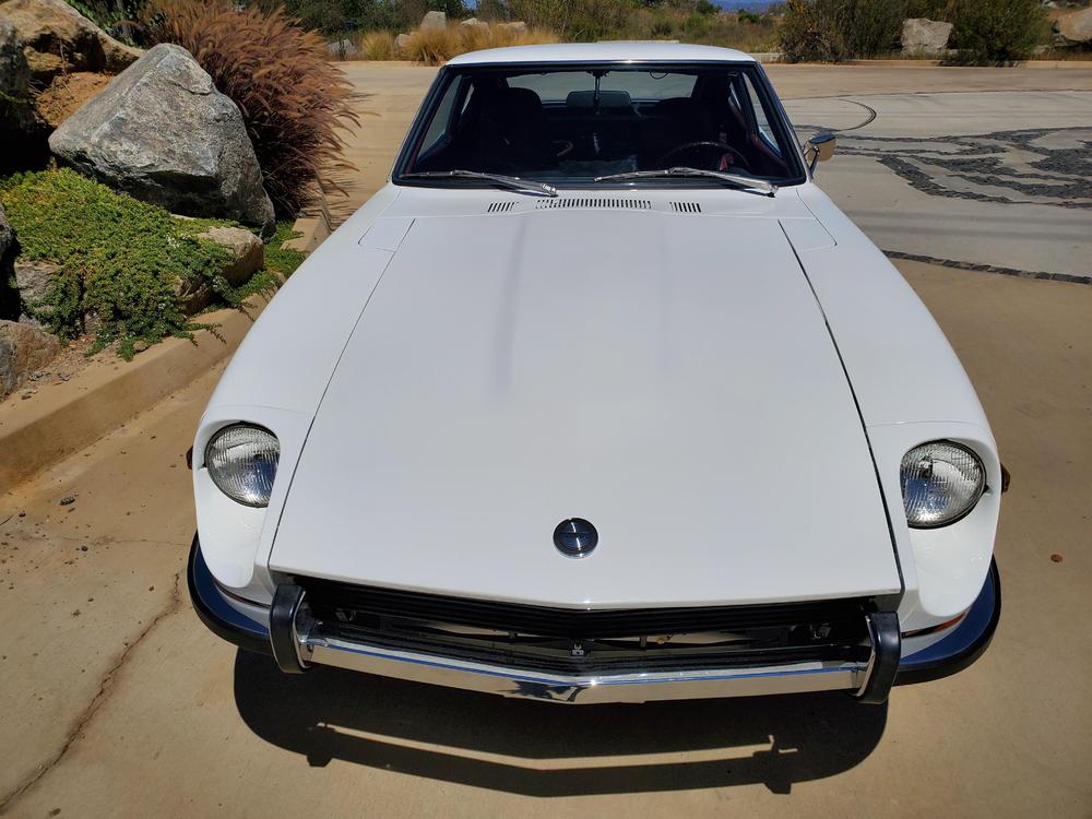
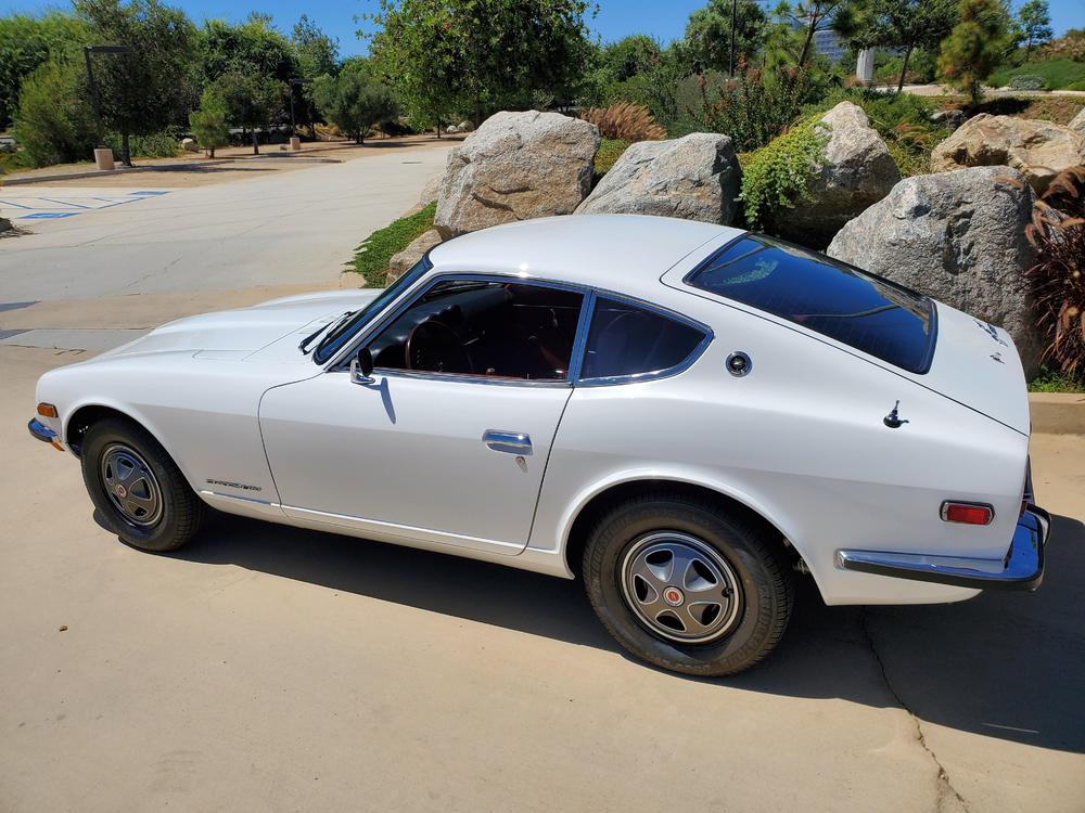
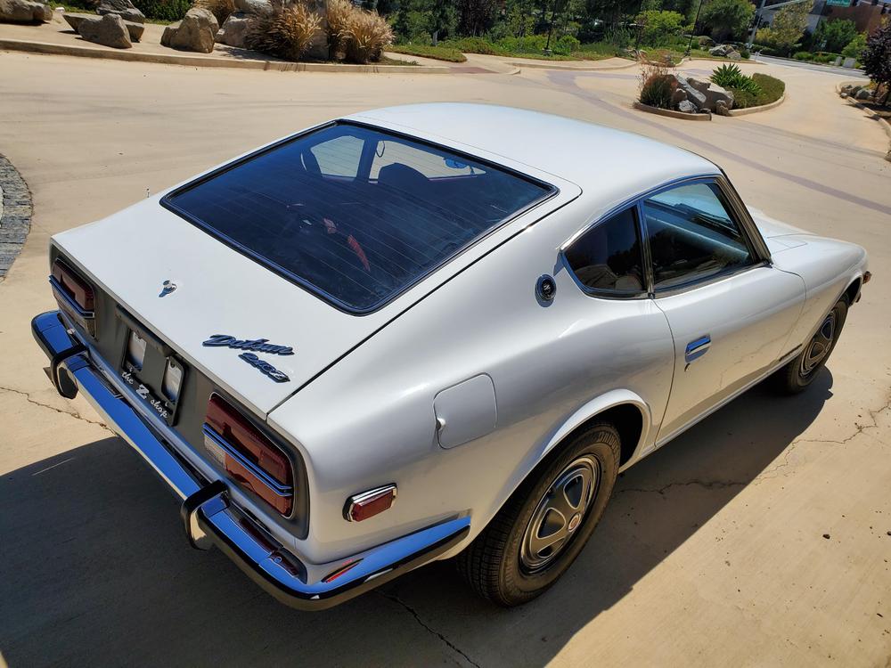
Took her out for a quick photoshoot. Car is running very nice. Still waiting for a dash so the interior is incomplete, but otherwise she is just about finished.


 1 point
 -
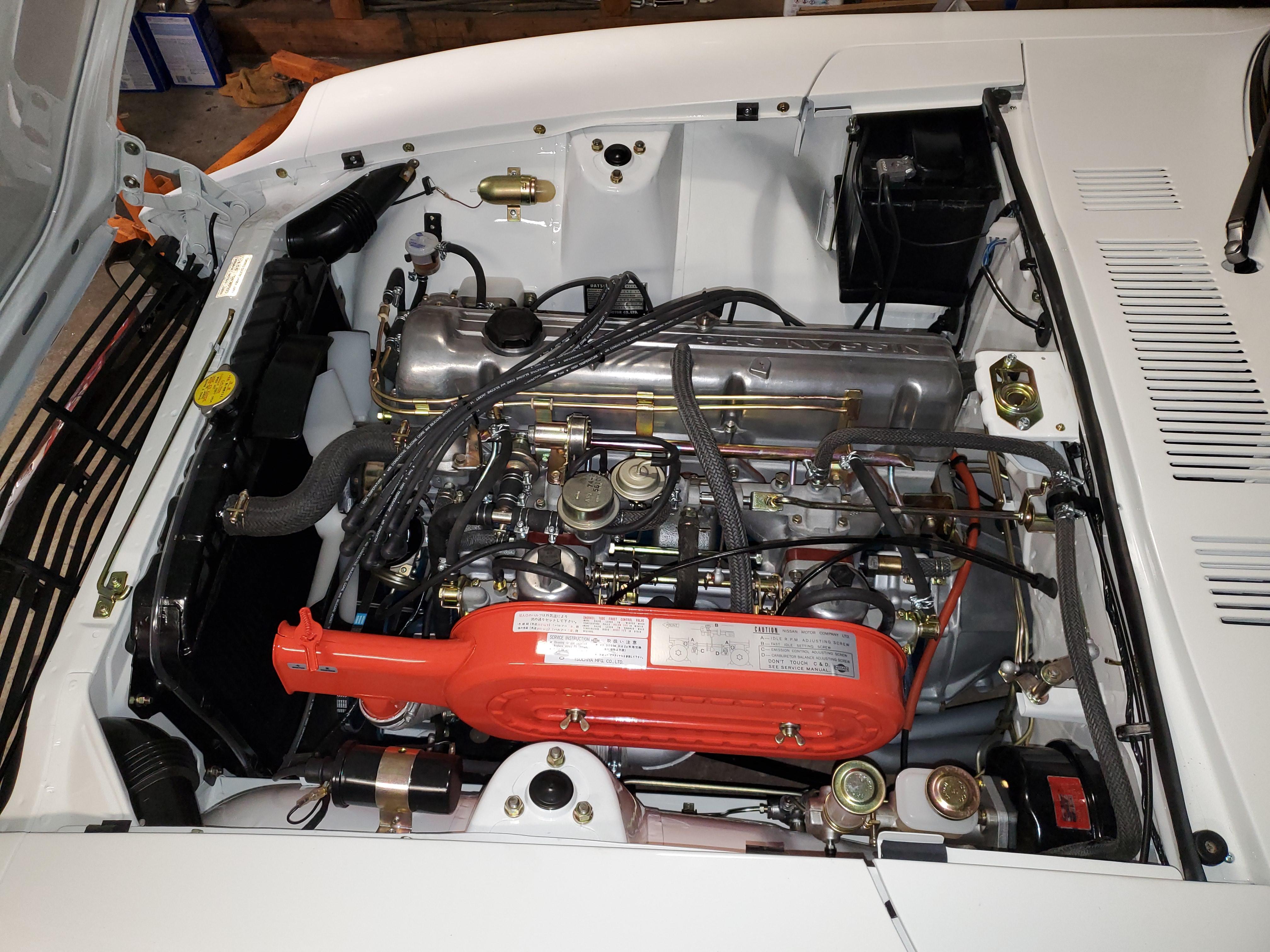
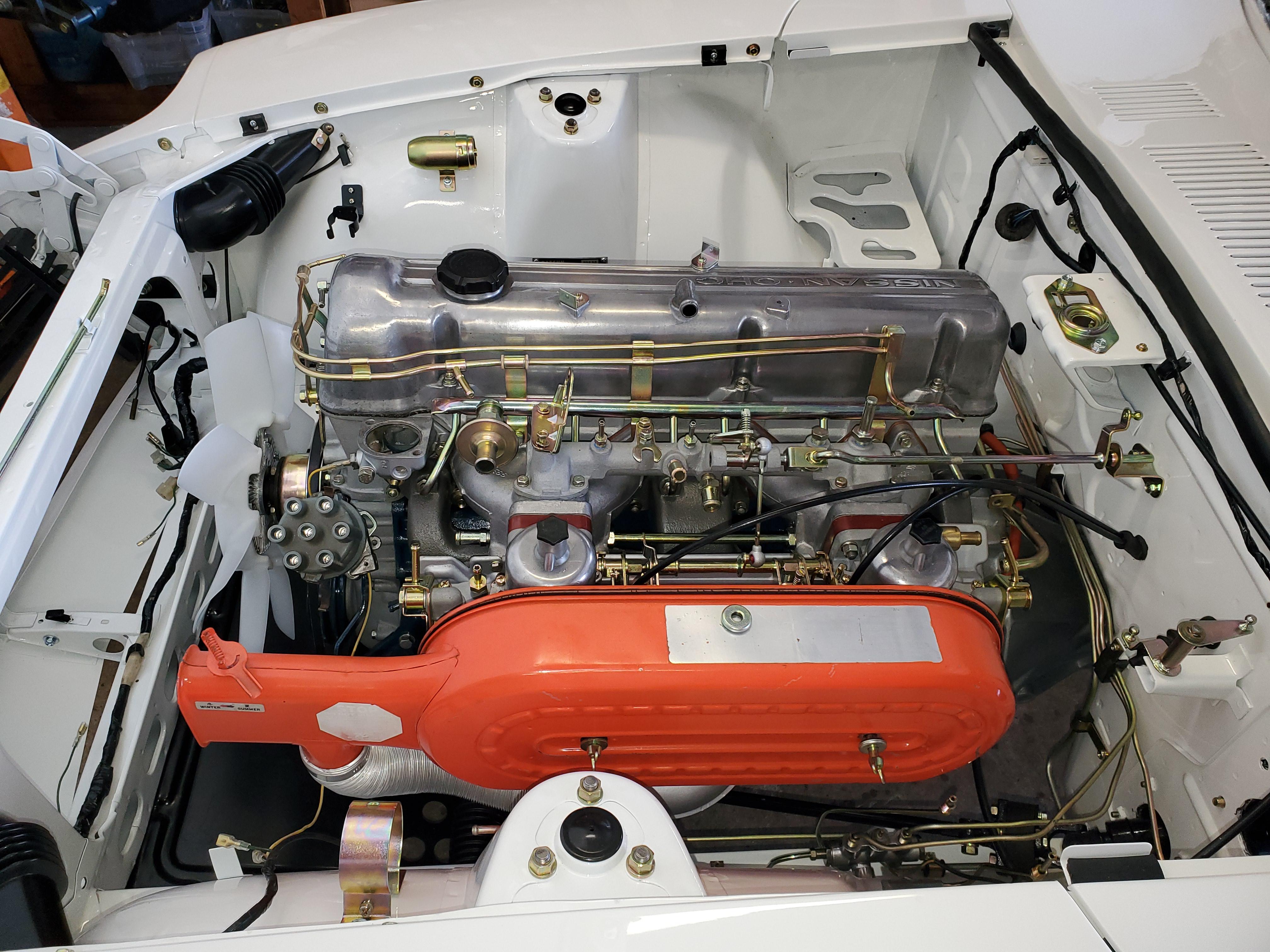
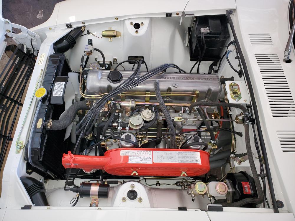
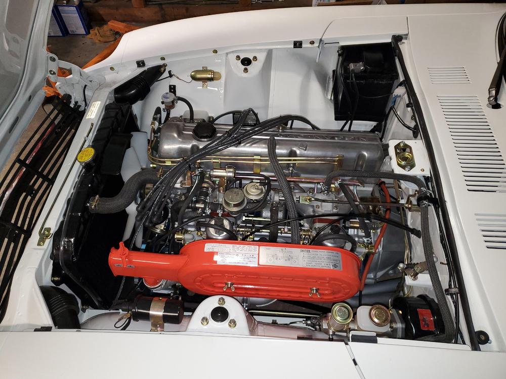
Thanks! Finally got the air cleaner back from the powdercoat shop. Turns out they were shut down for a week as one of the employees had COVID, thus the delay. Now just waiting for radiator decals and engine bay is complete.
 1 point
 -
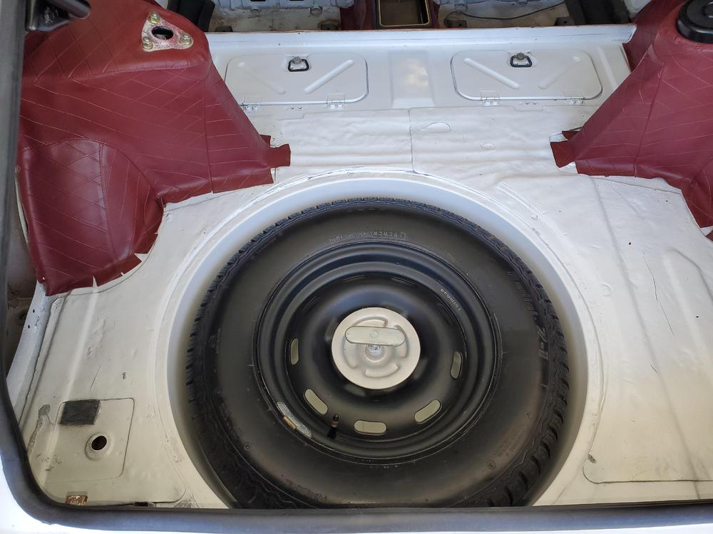
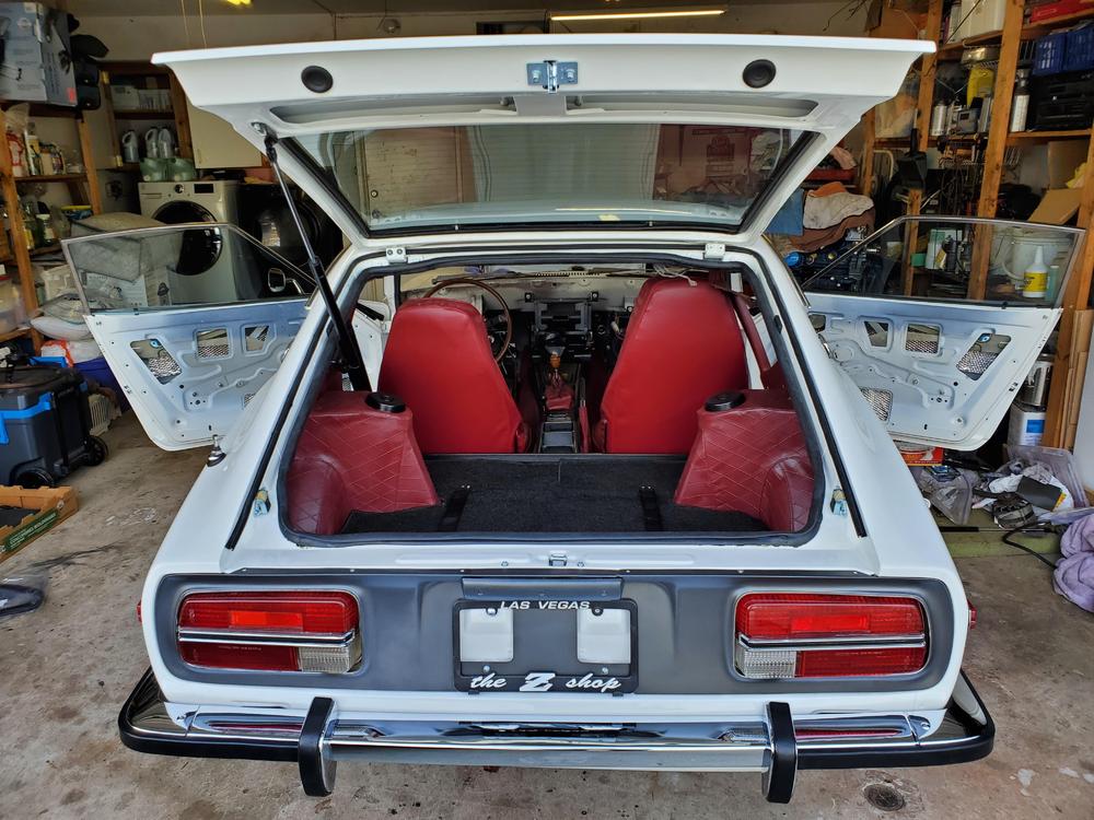
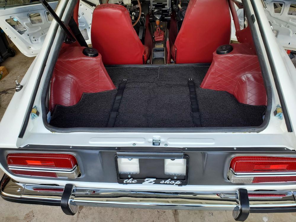
Here's a few more photo updates. Assembly is moving right along. Sent gas tank and radiator out last week for sealing and re-core. Ordered braided hoses and exhaust parts from Jay. The long poles are the headliner and vintage dash. Hopefully will have this running is a couple weeks.


 1 point
 -
0 pointsChicago is going all remote in their school system. Of course this means that the poorer families will be disadvantaged. https://www.cnn.com/2020/08/05/us/chicago-schools-virtual-coronavirus/index.html0 points