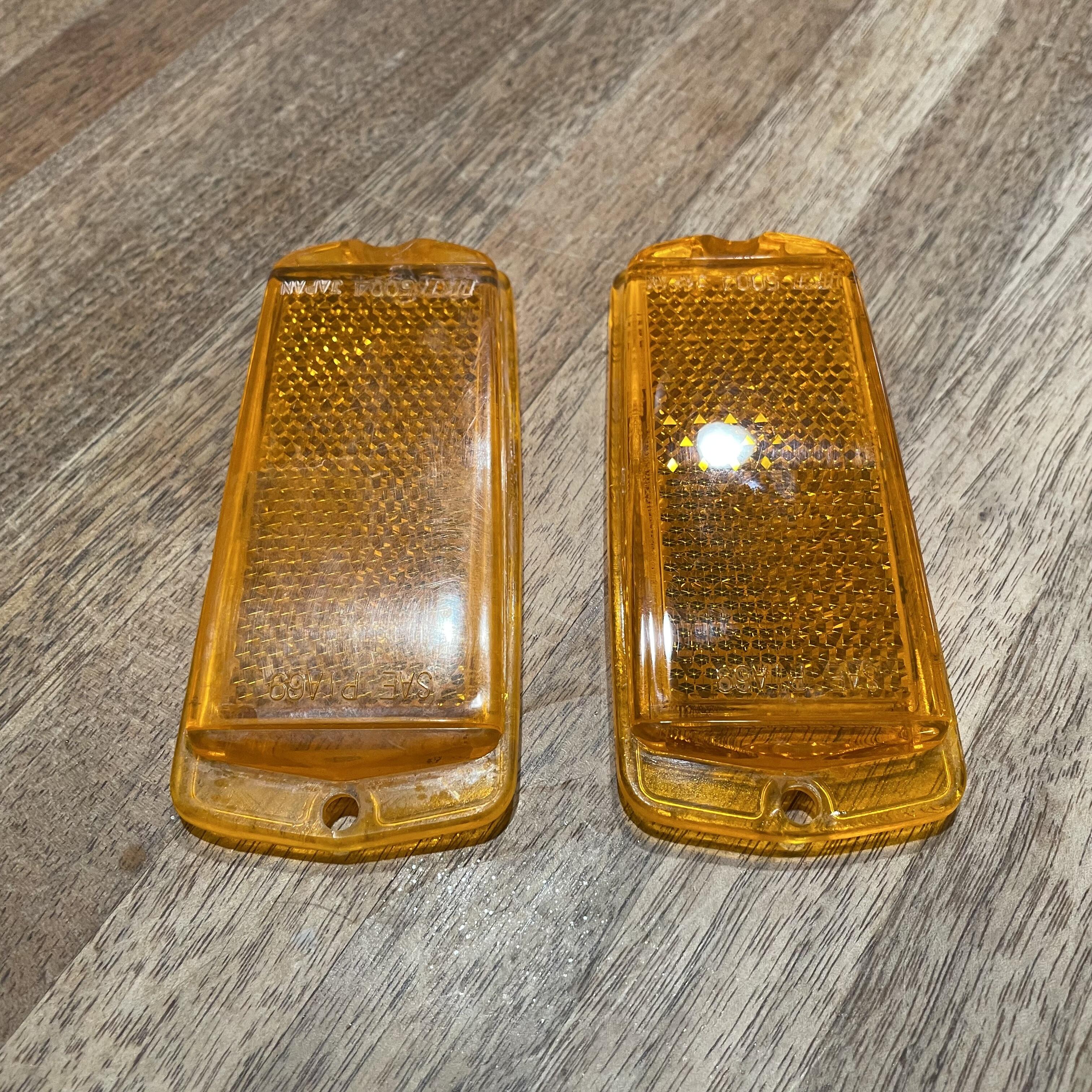
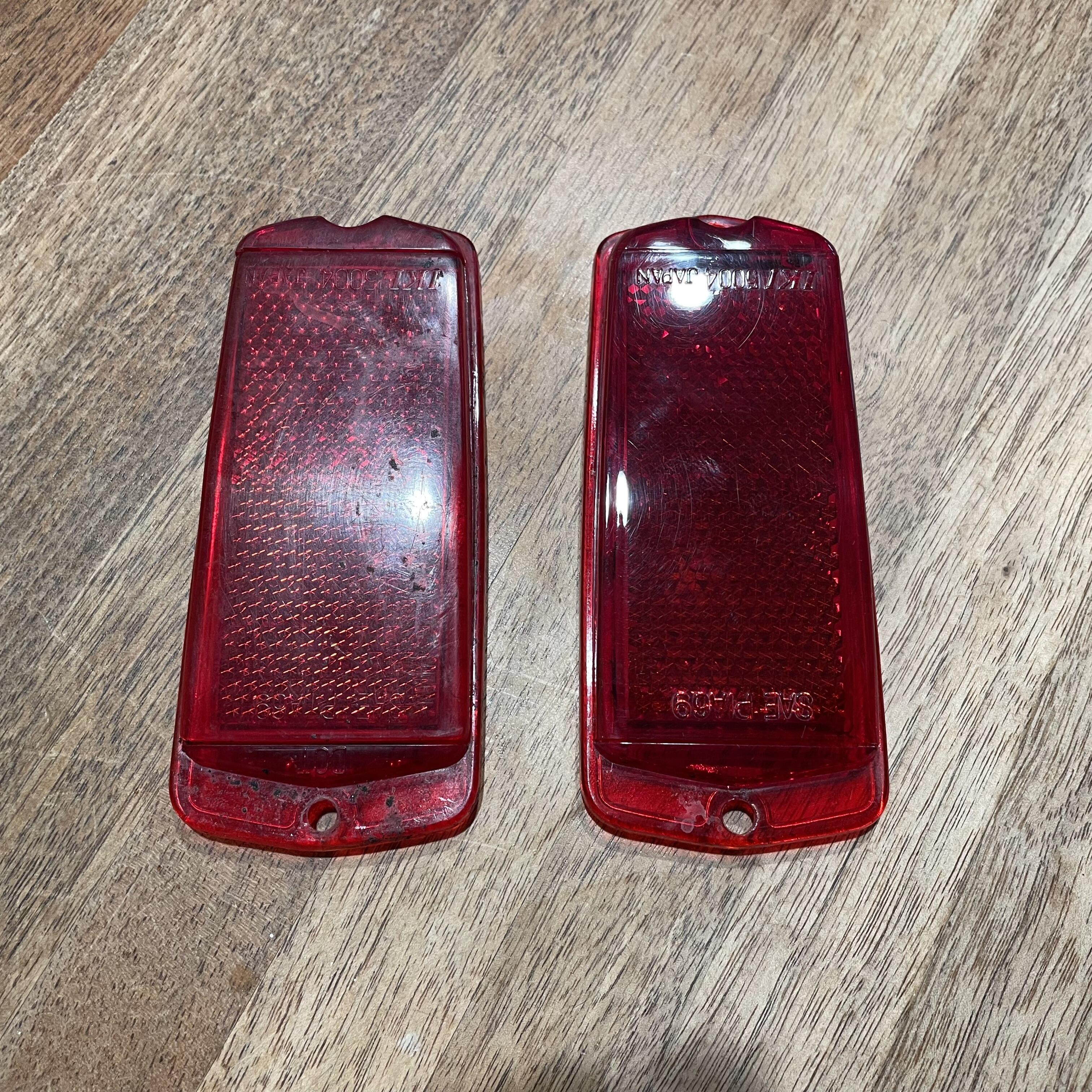
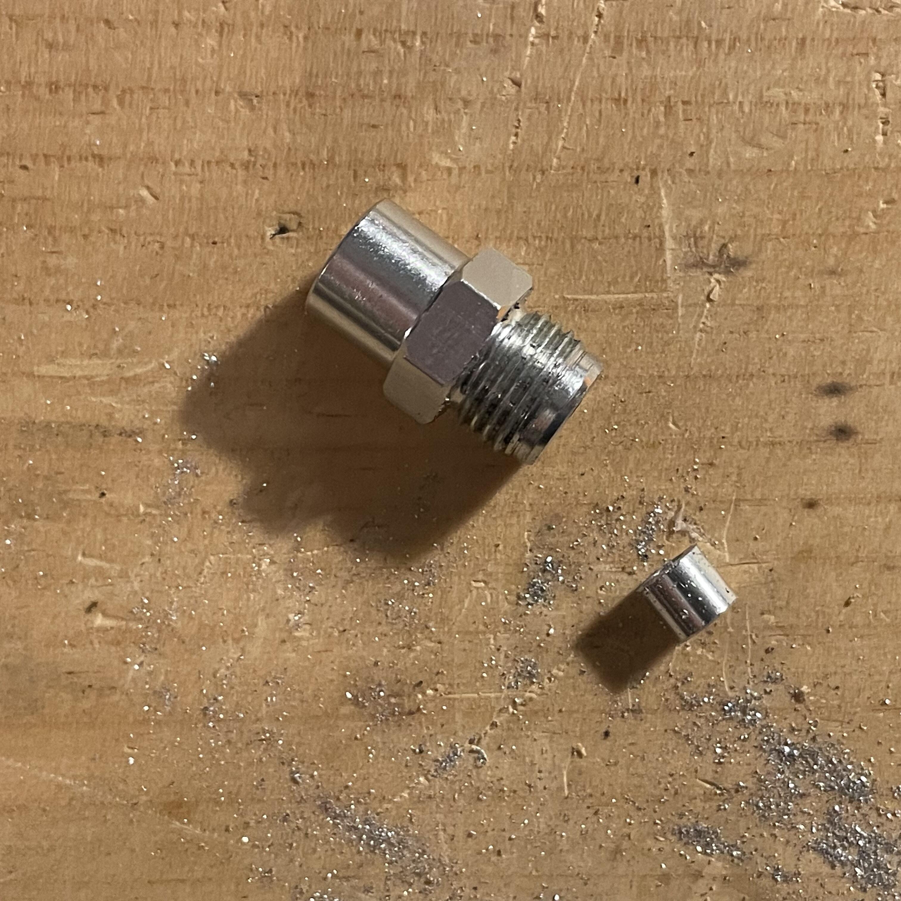
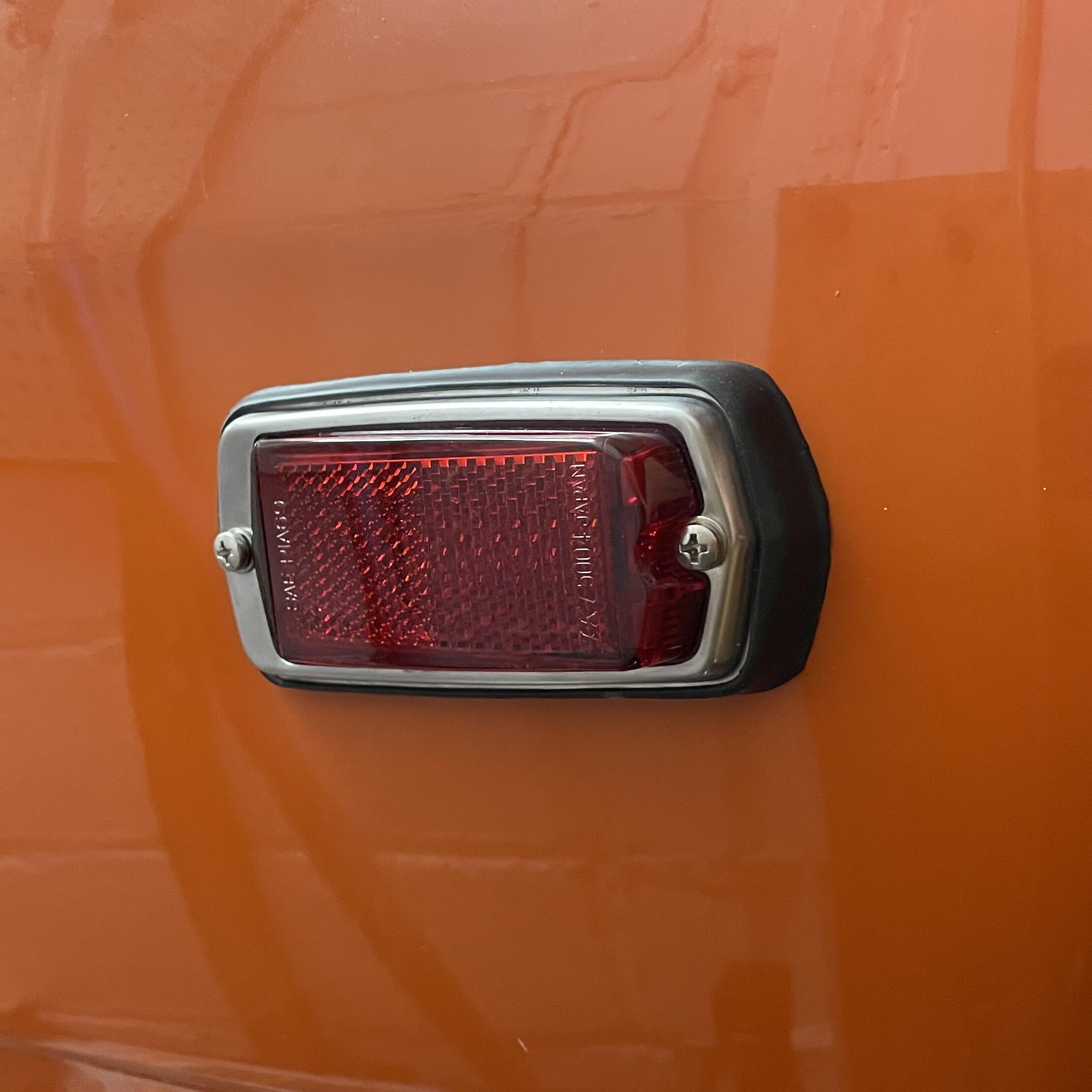
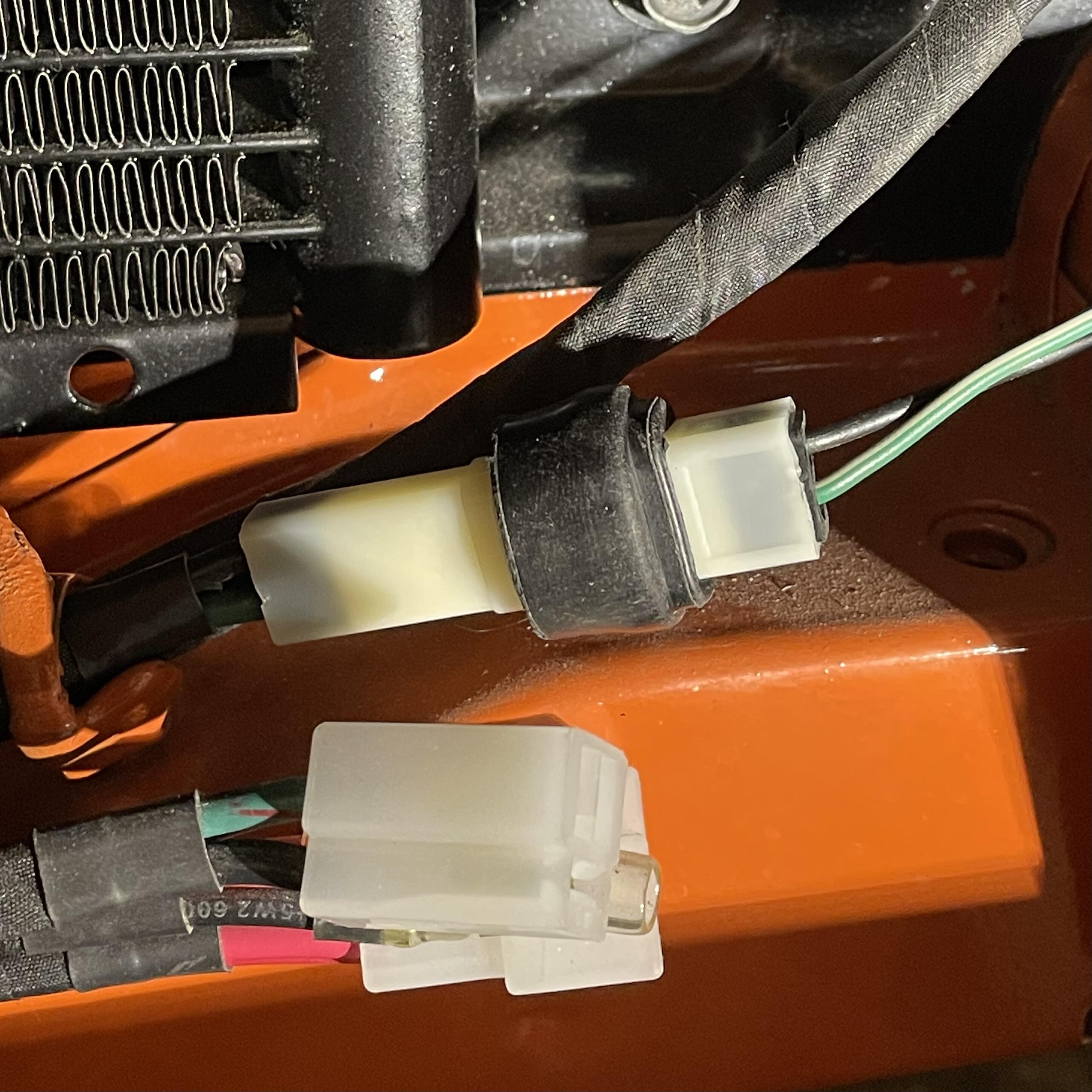
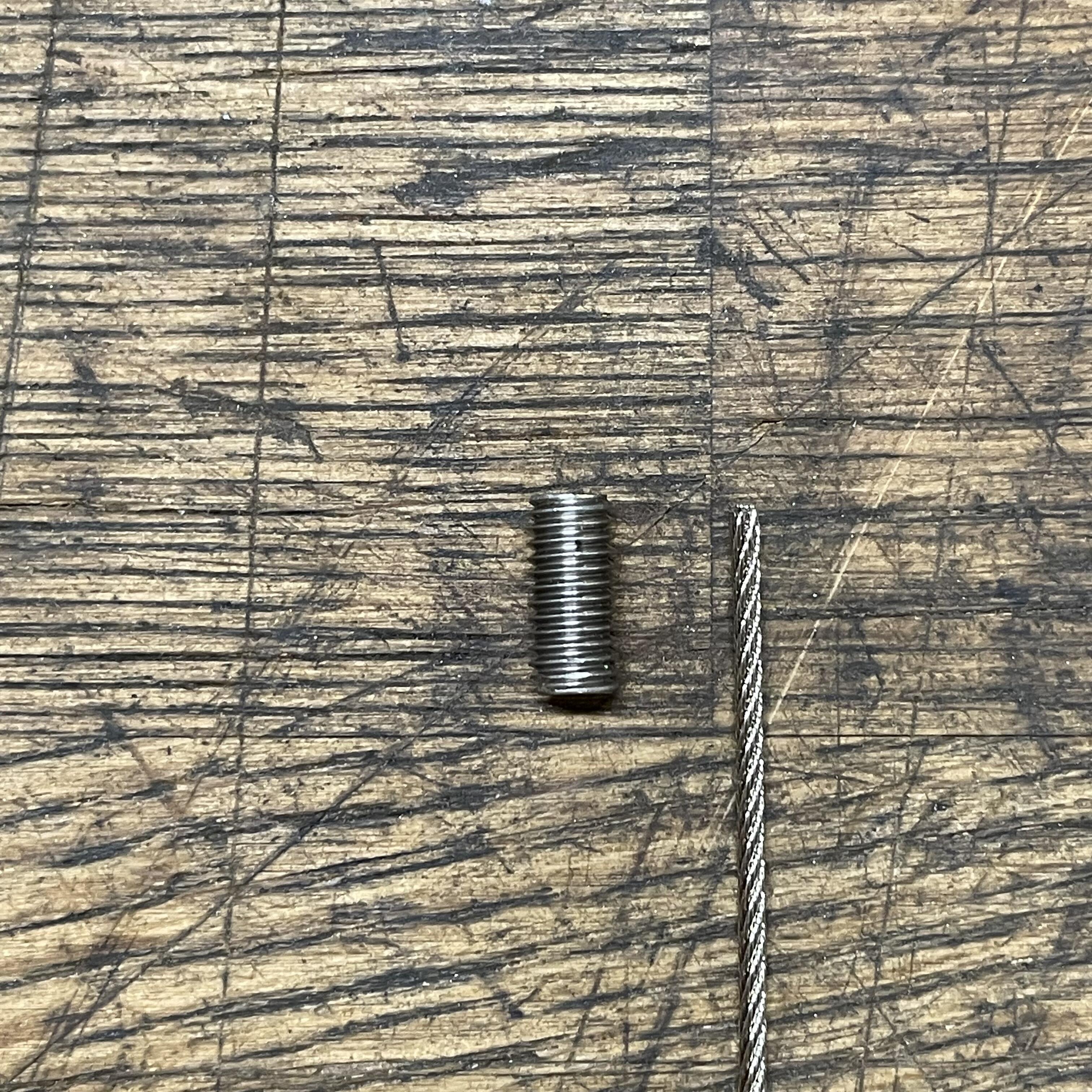
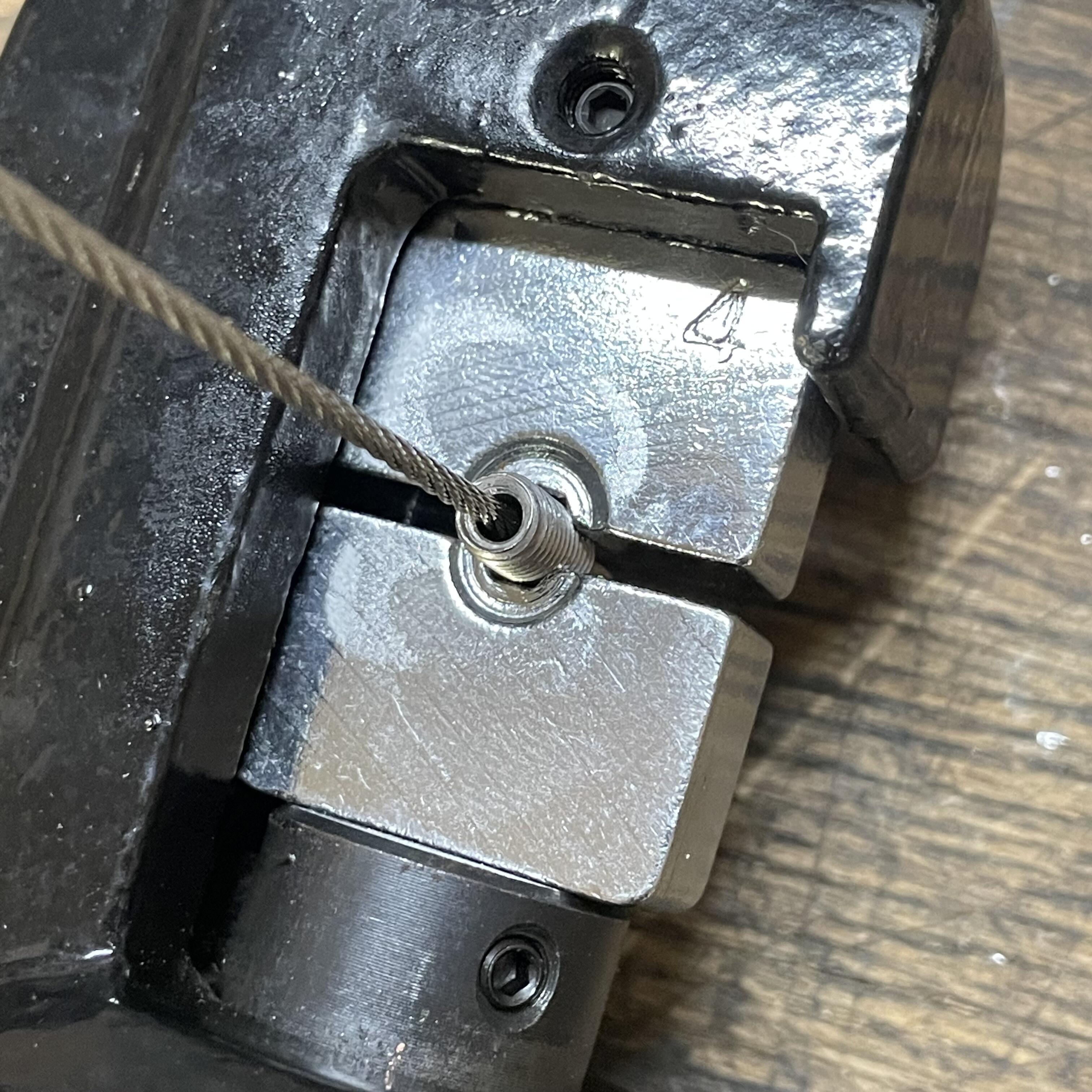
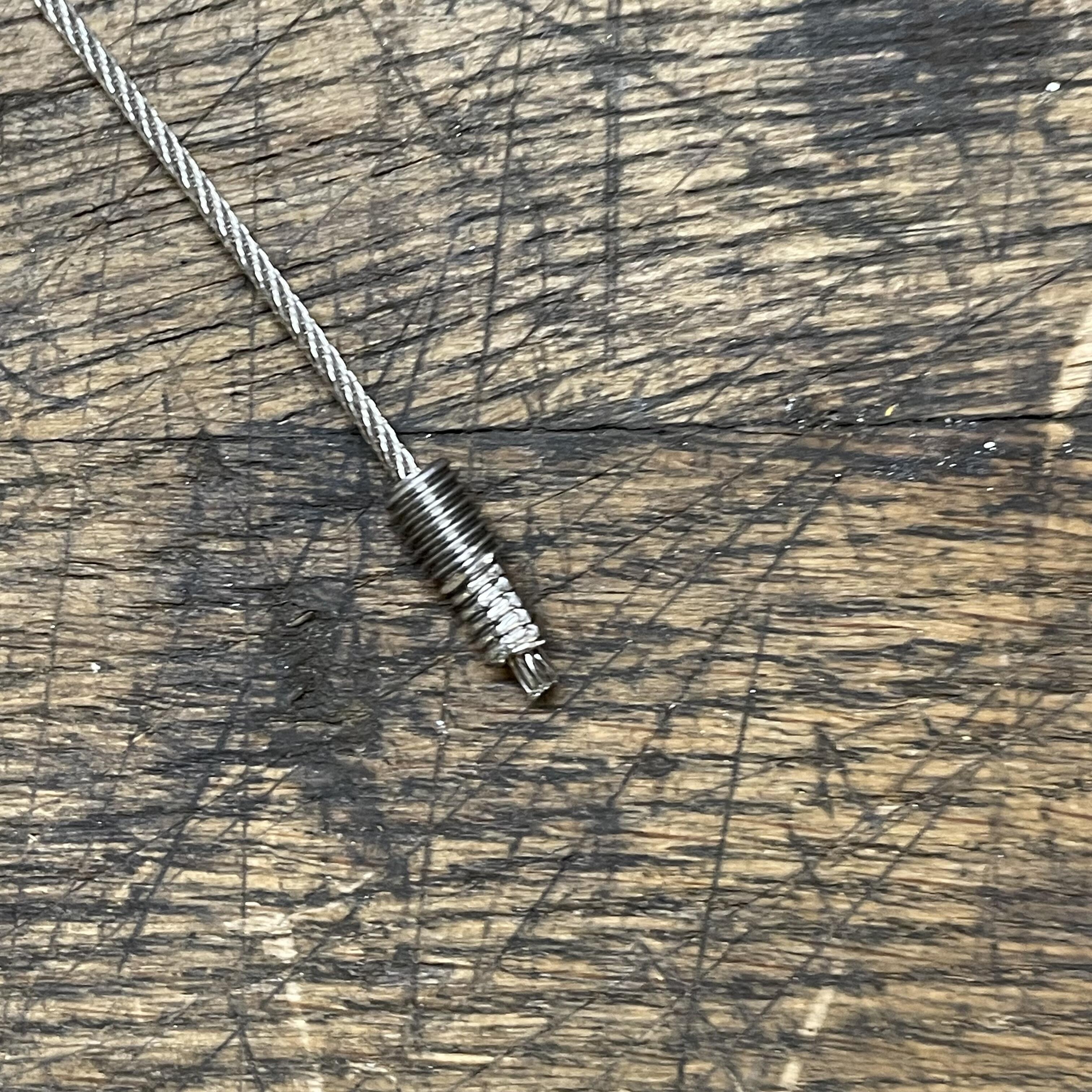
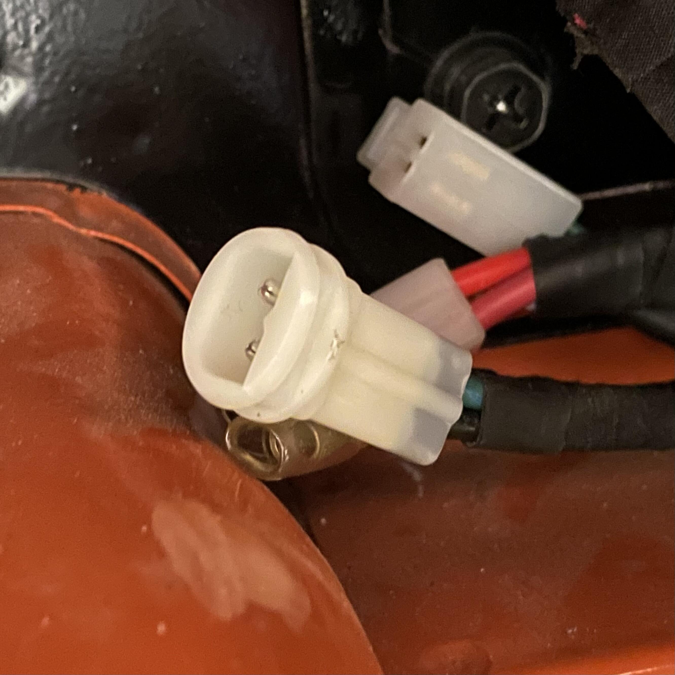
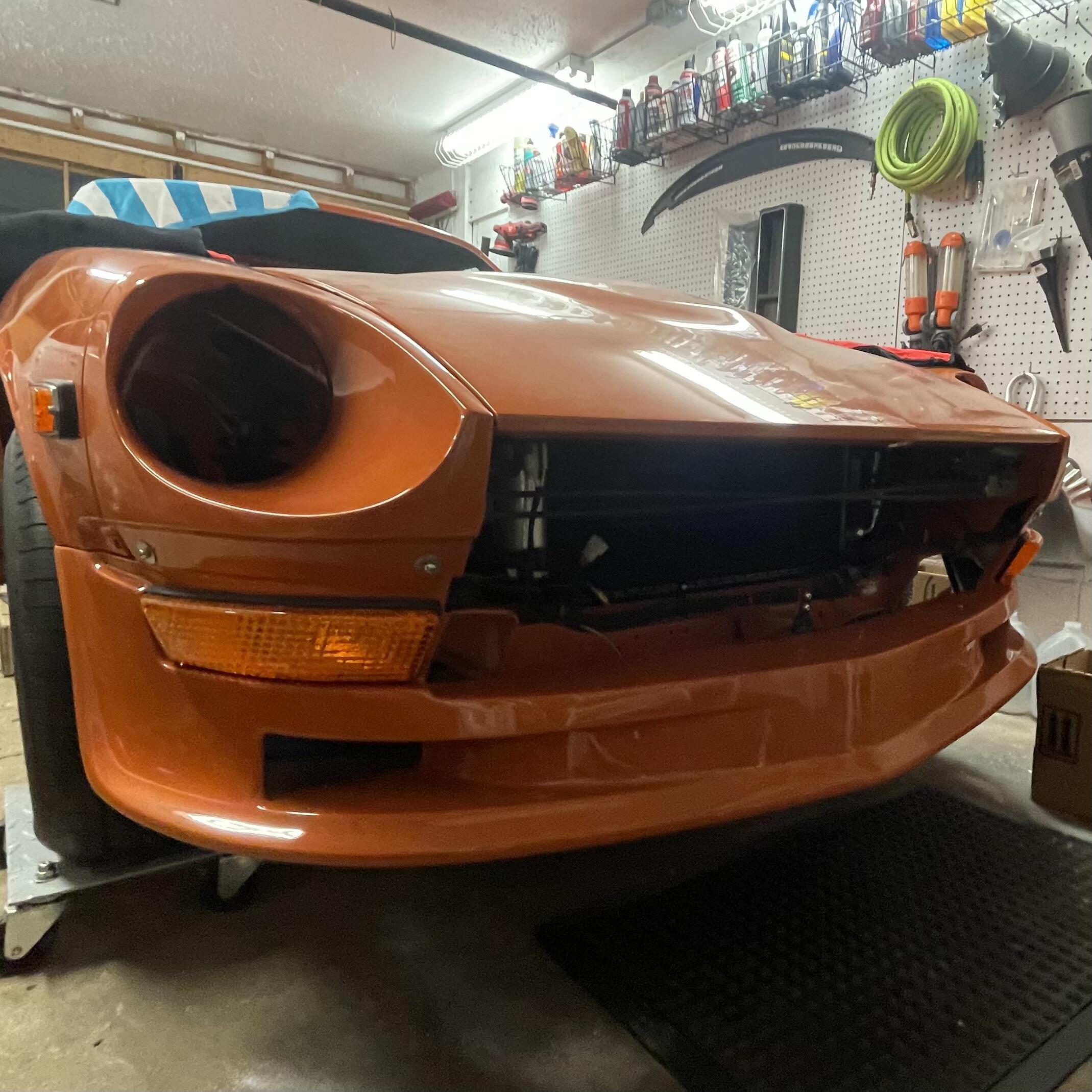
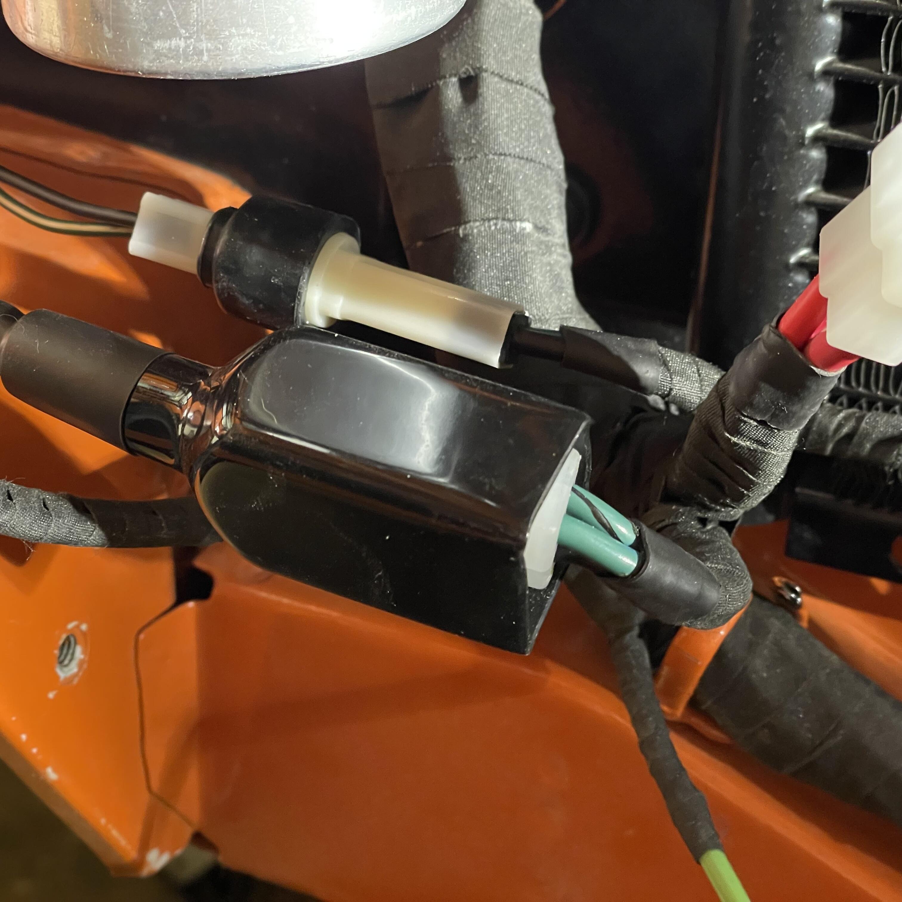
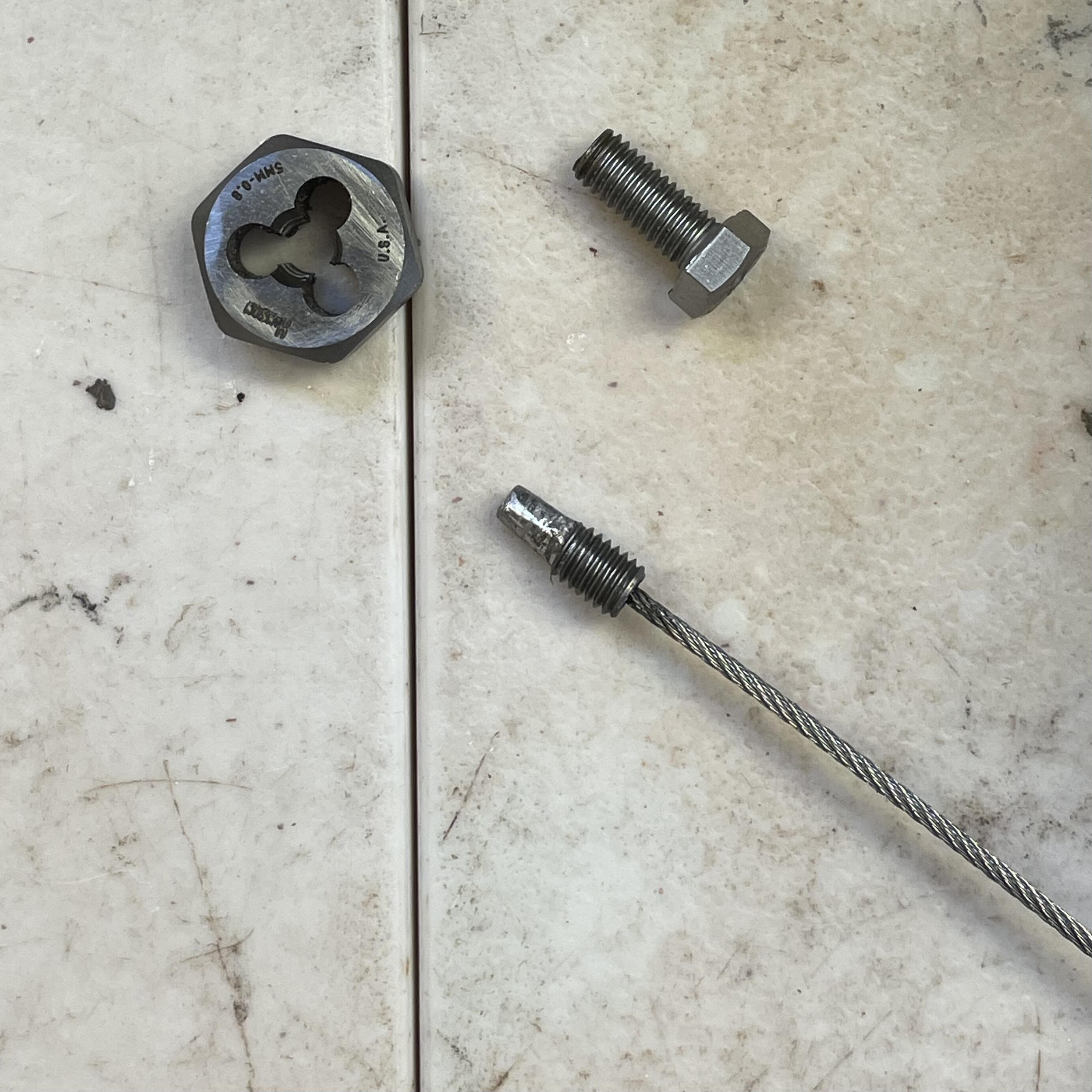
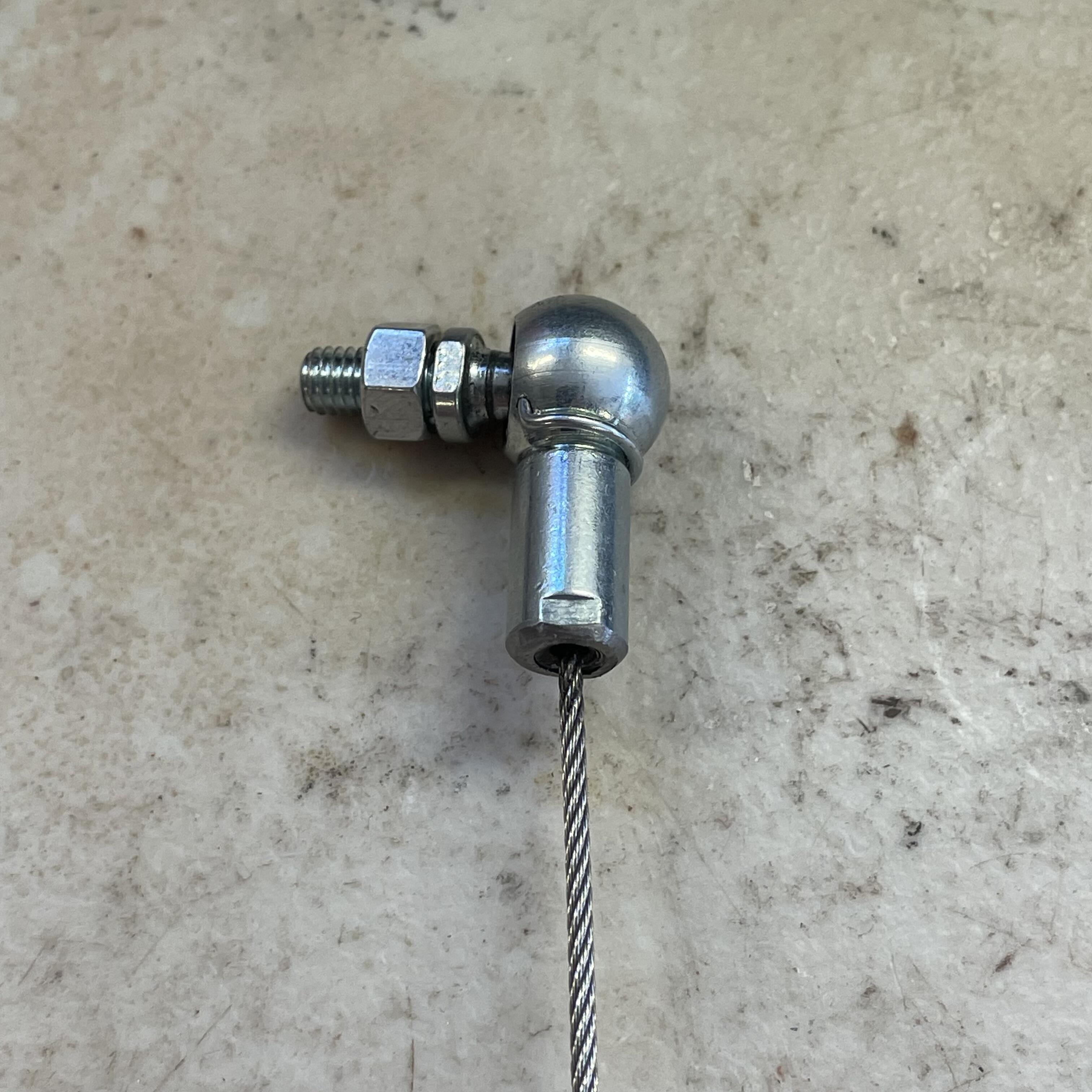
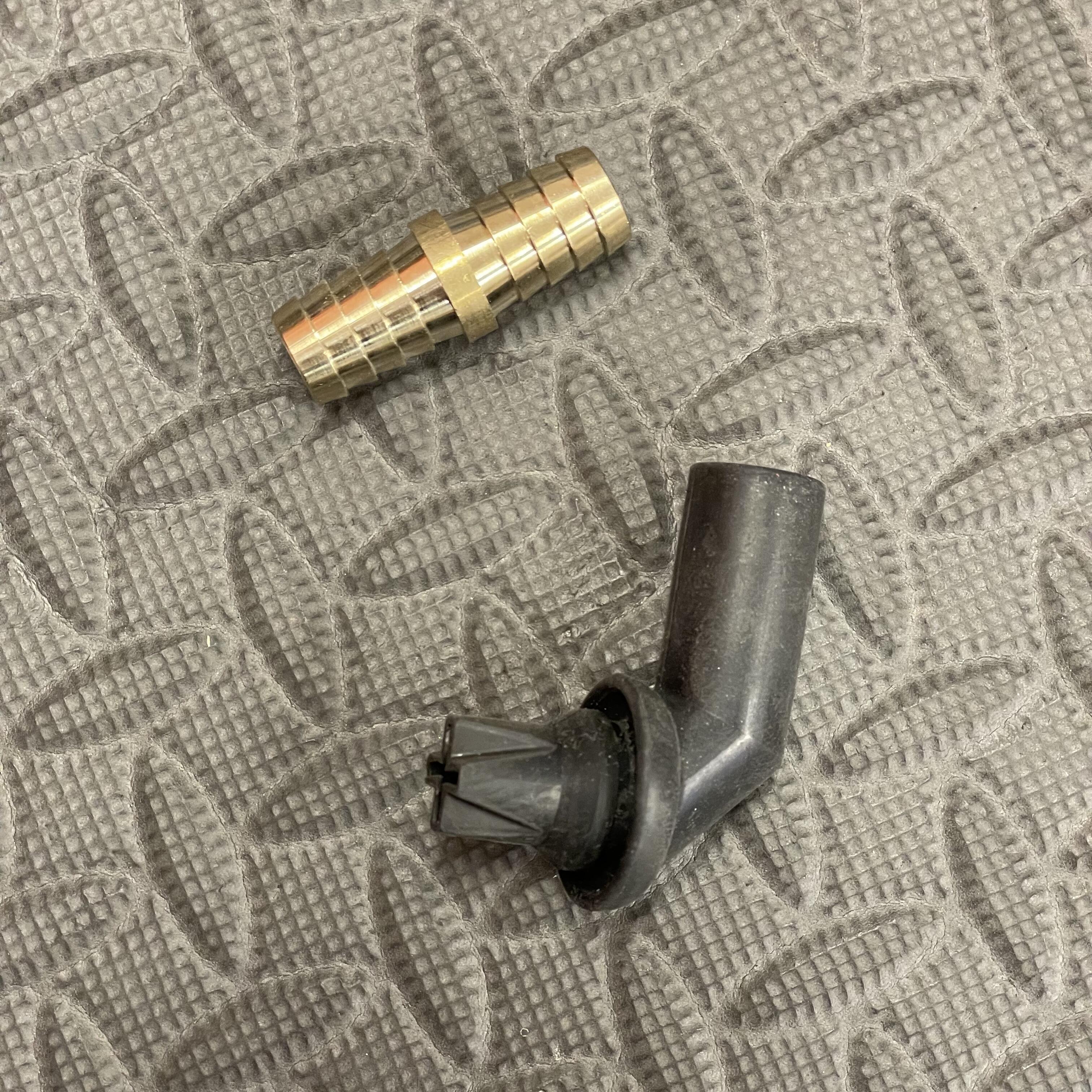
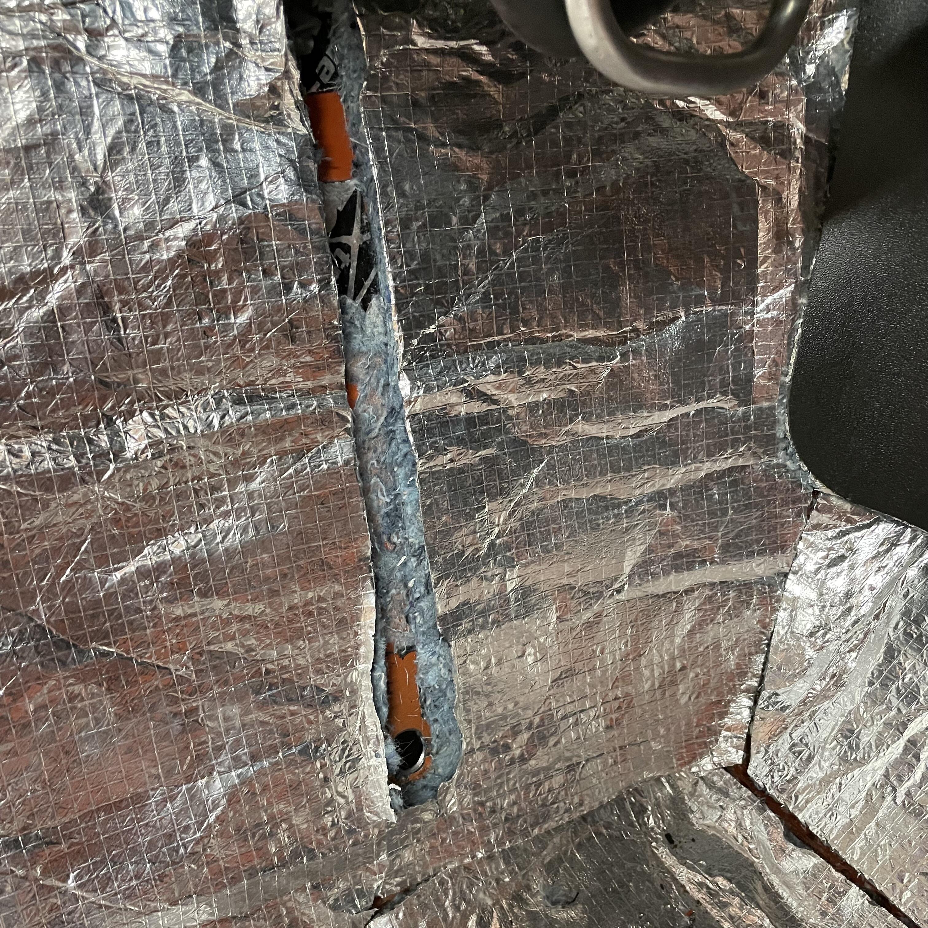
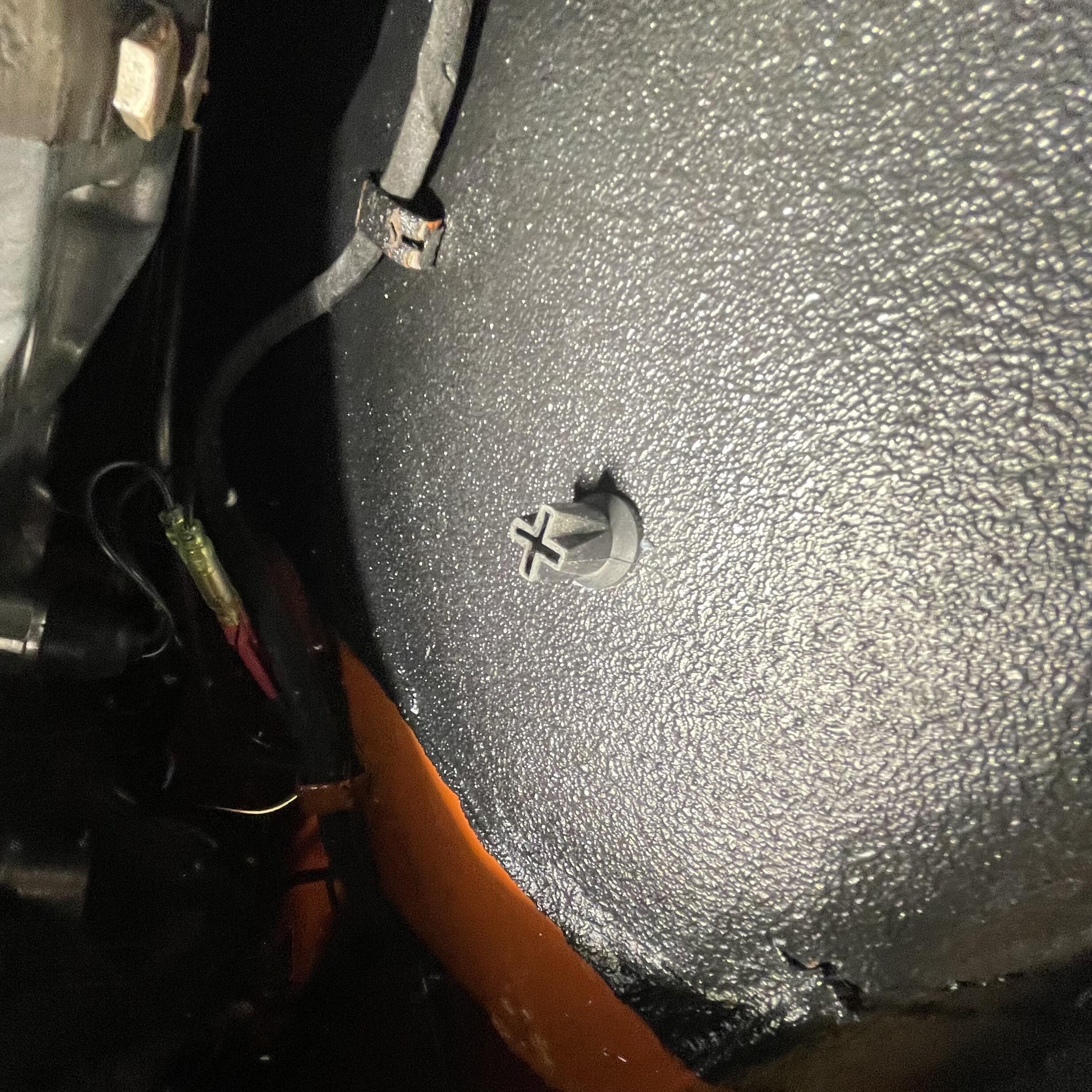
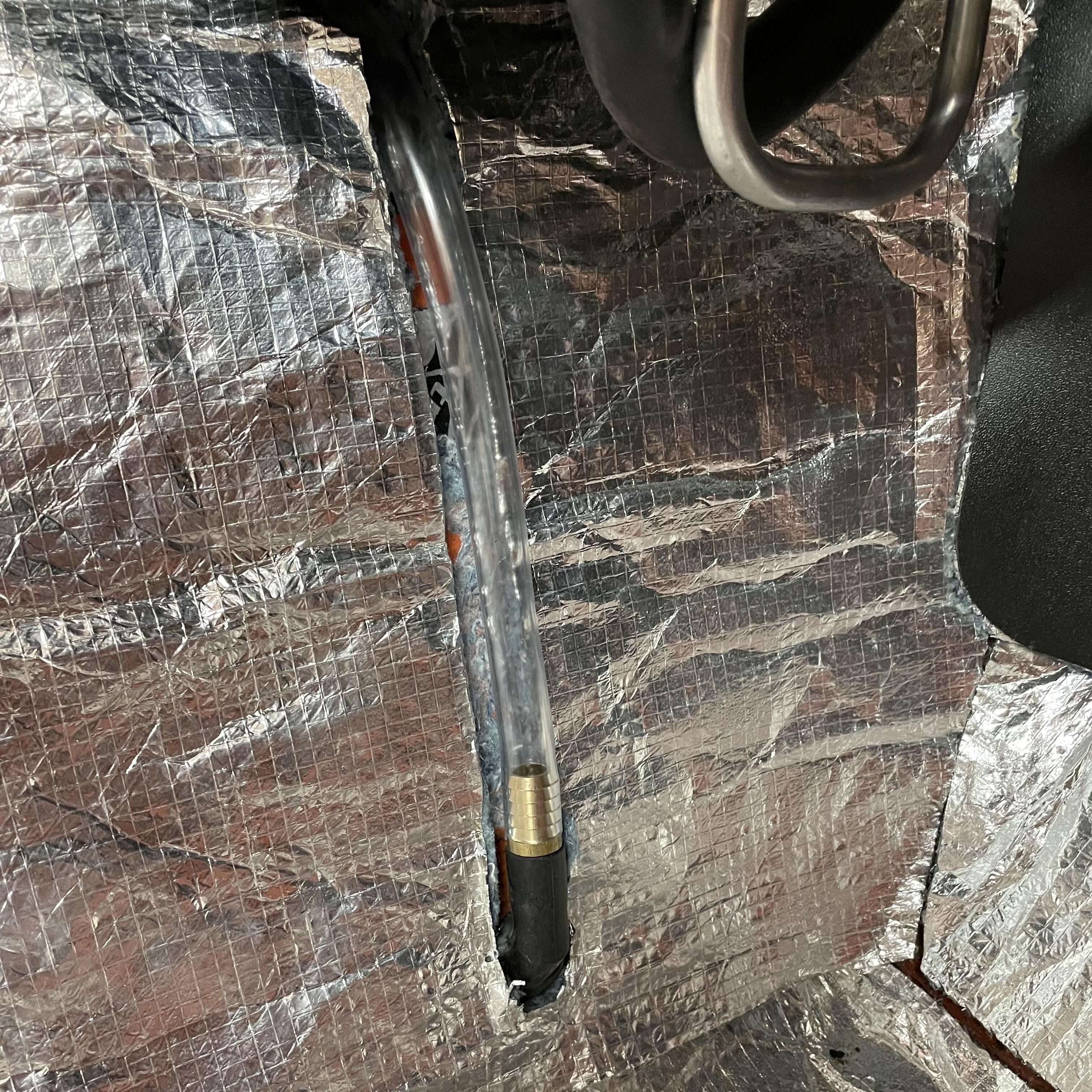
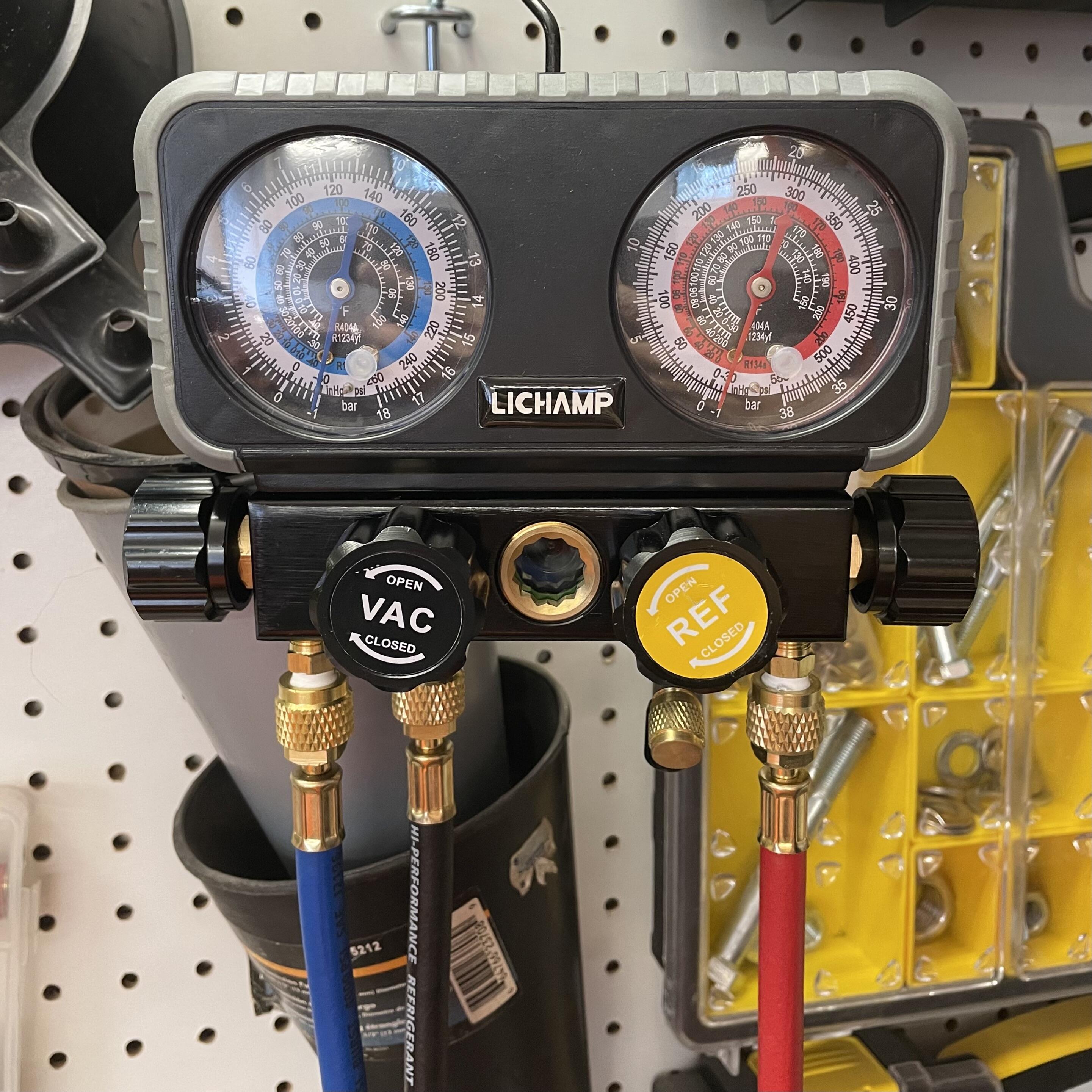
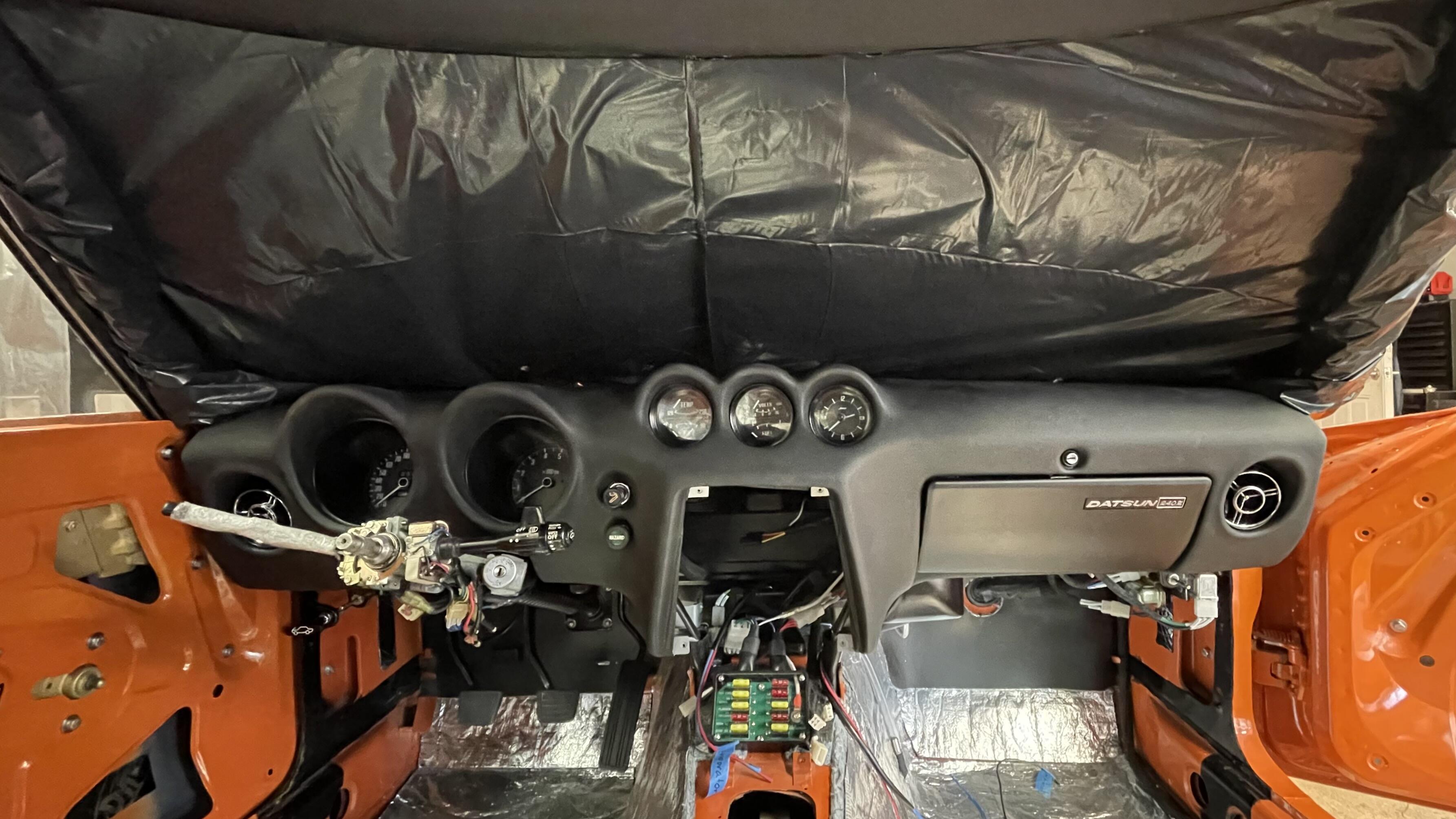
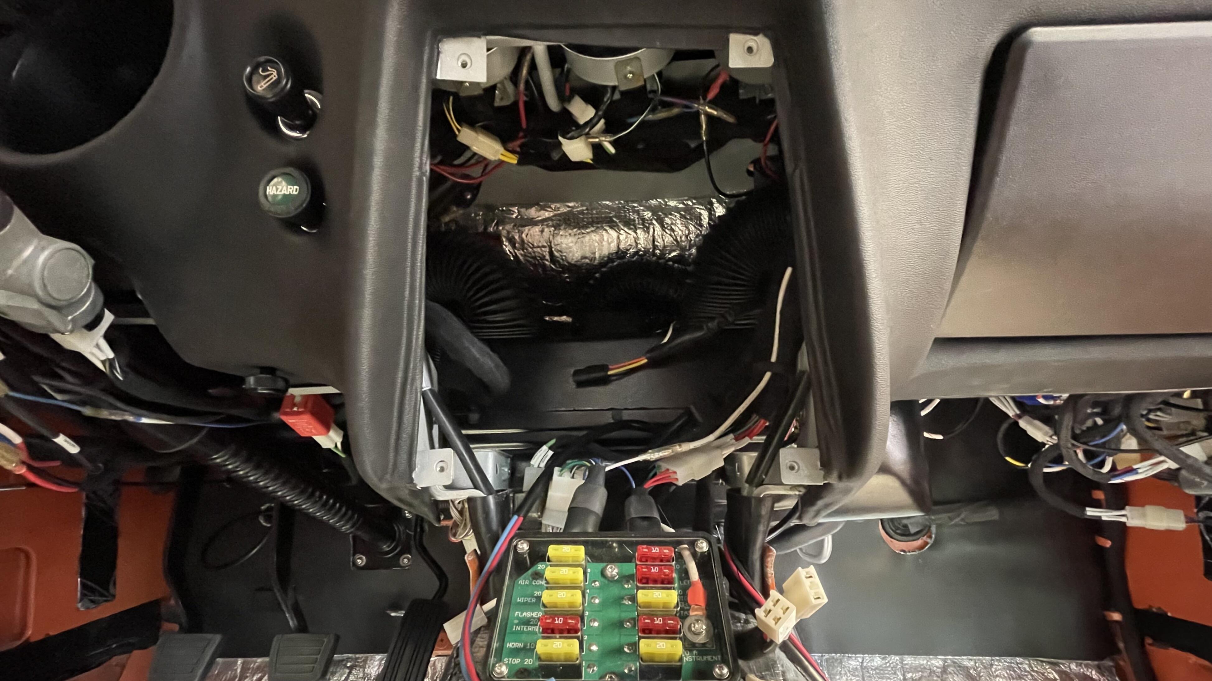
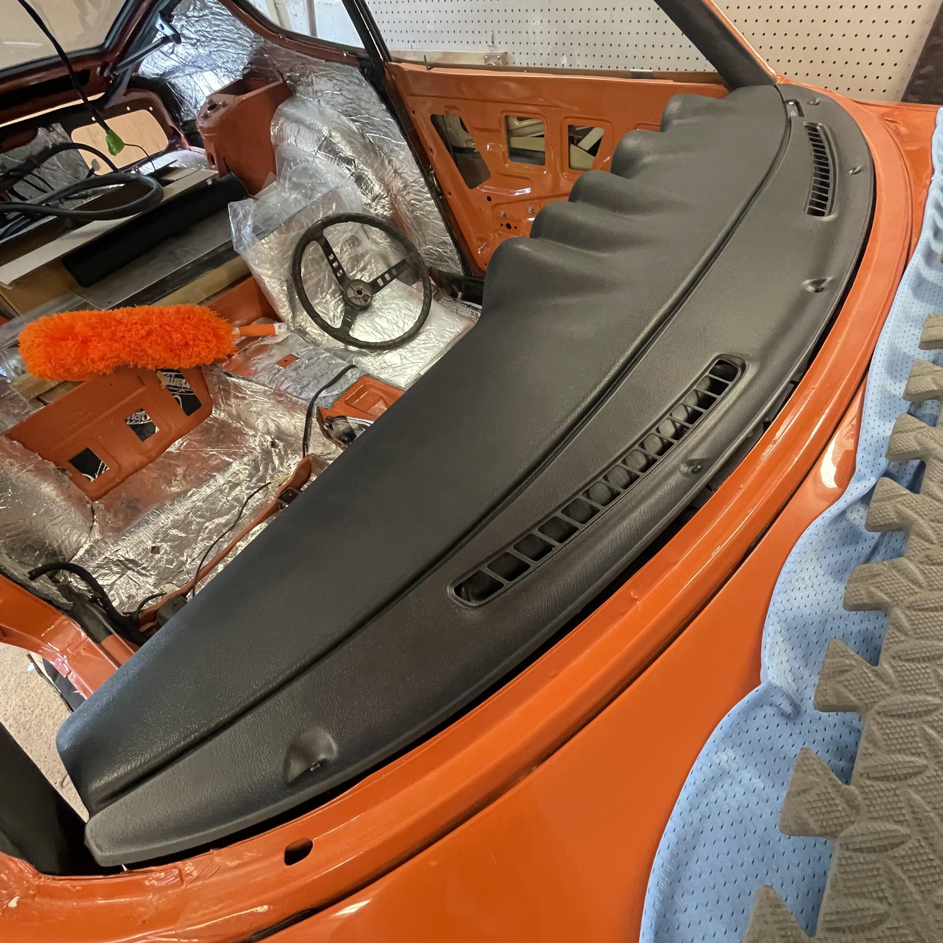
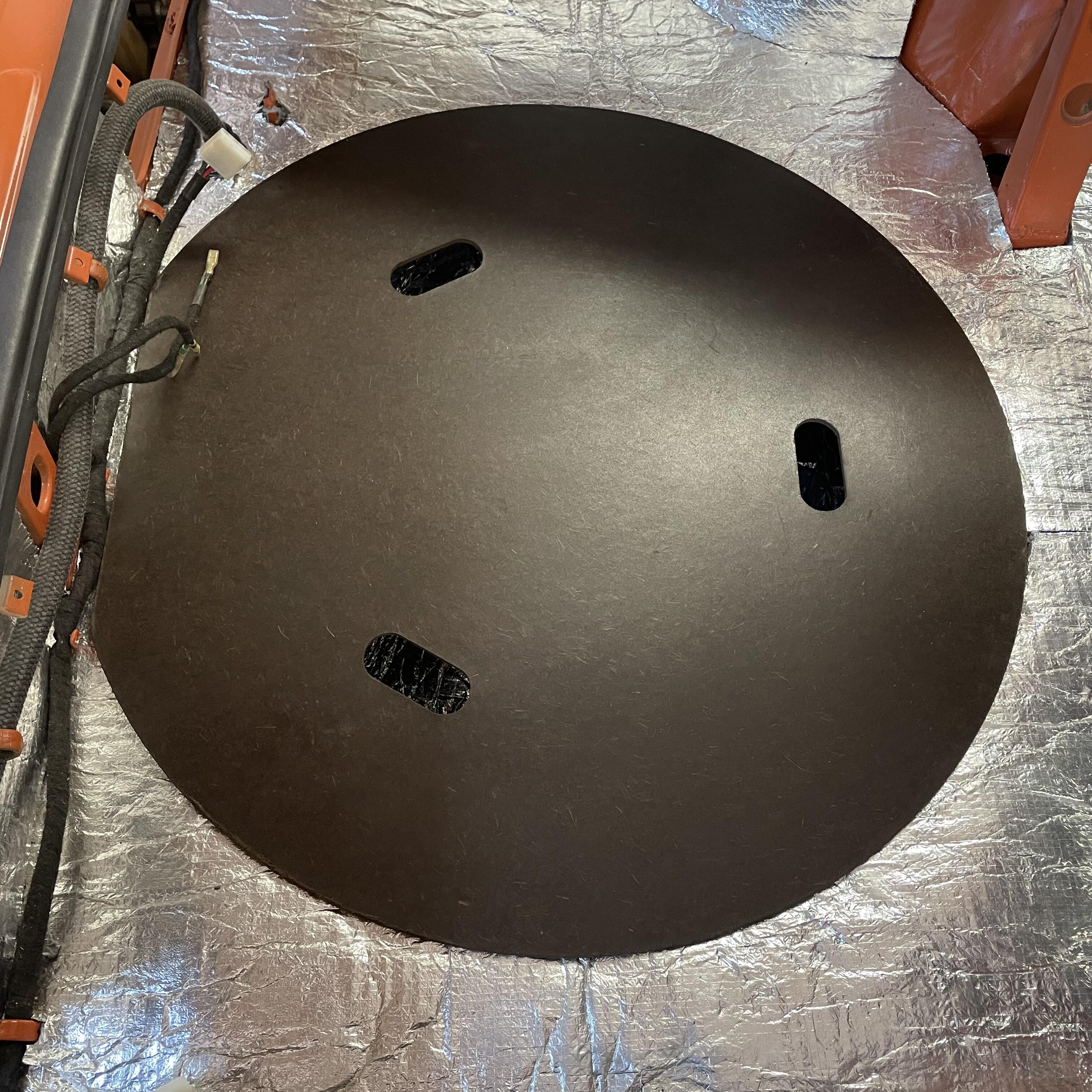
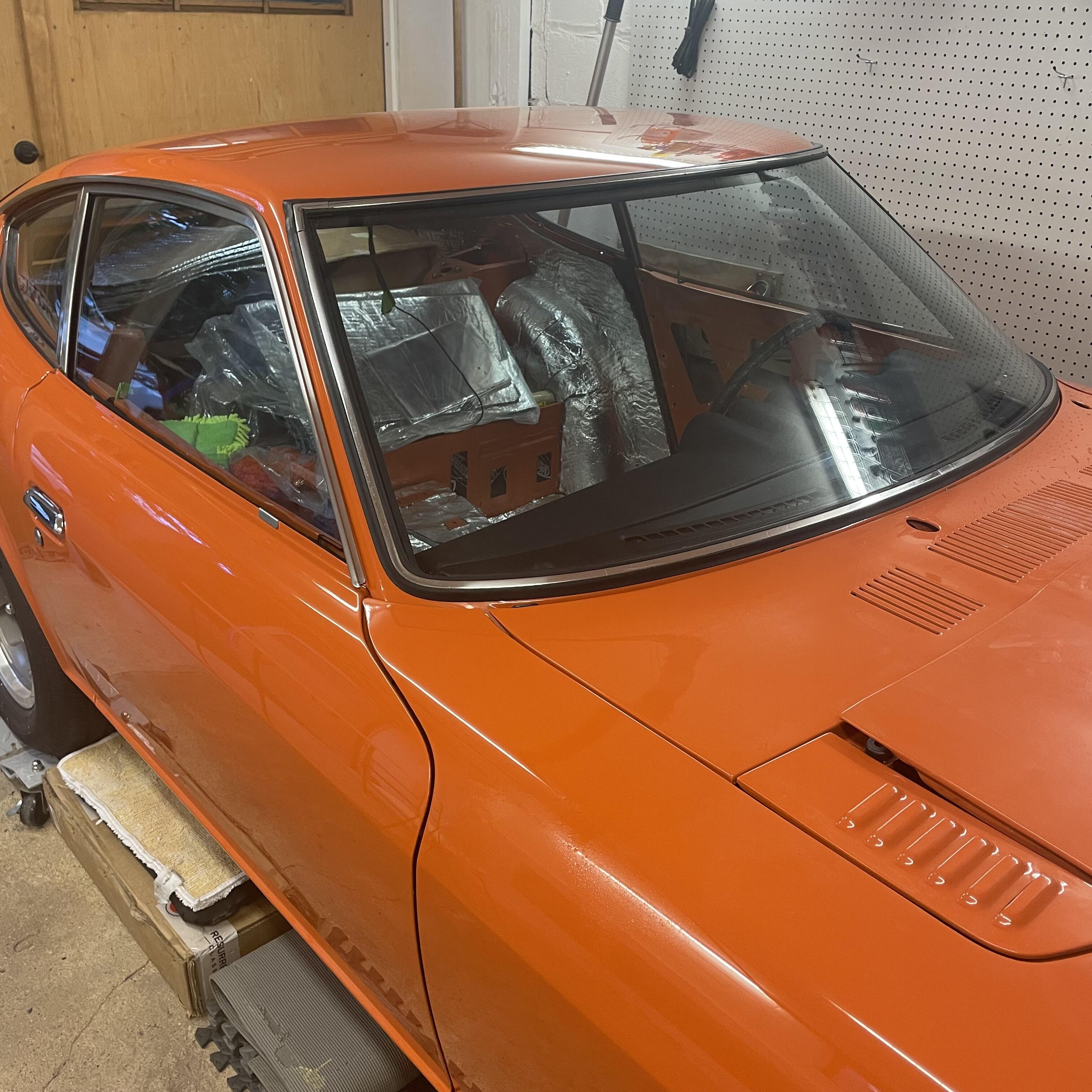
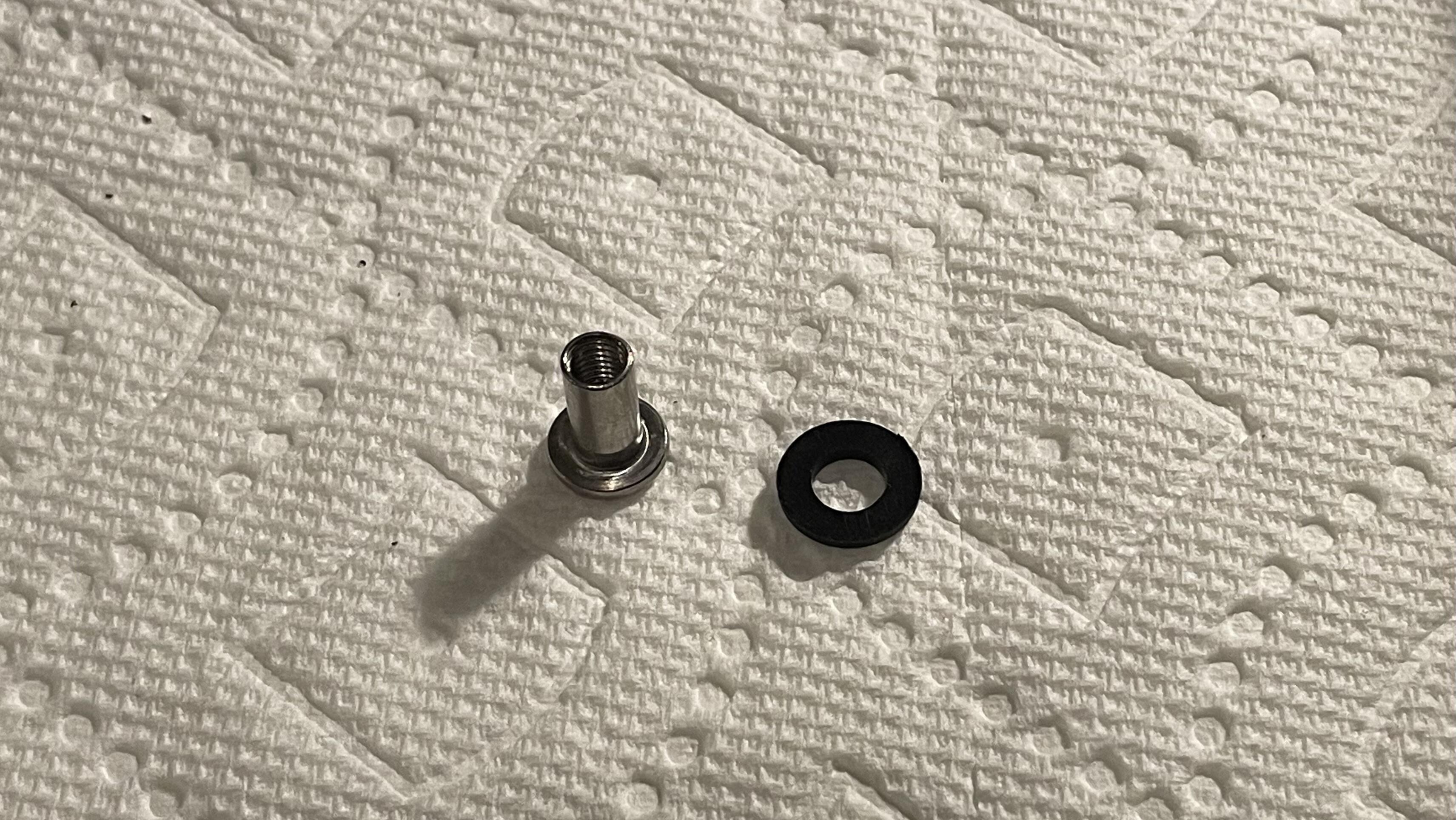
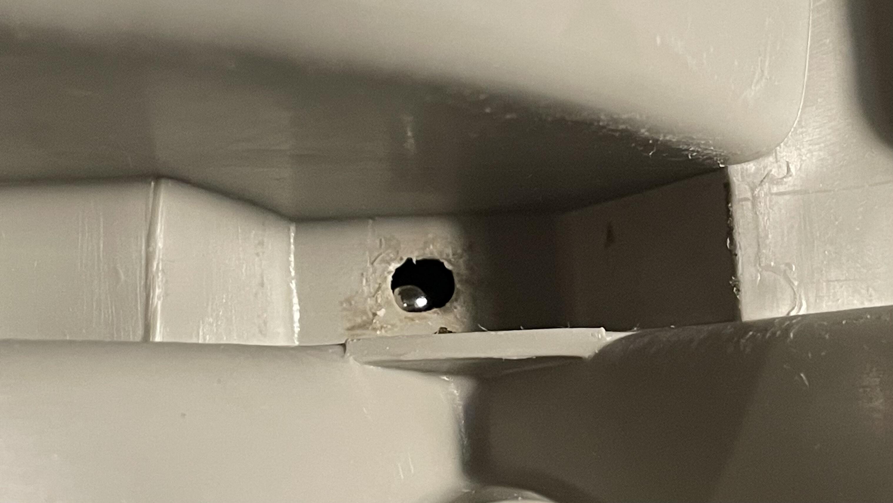
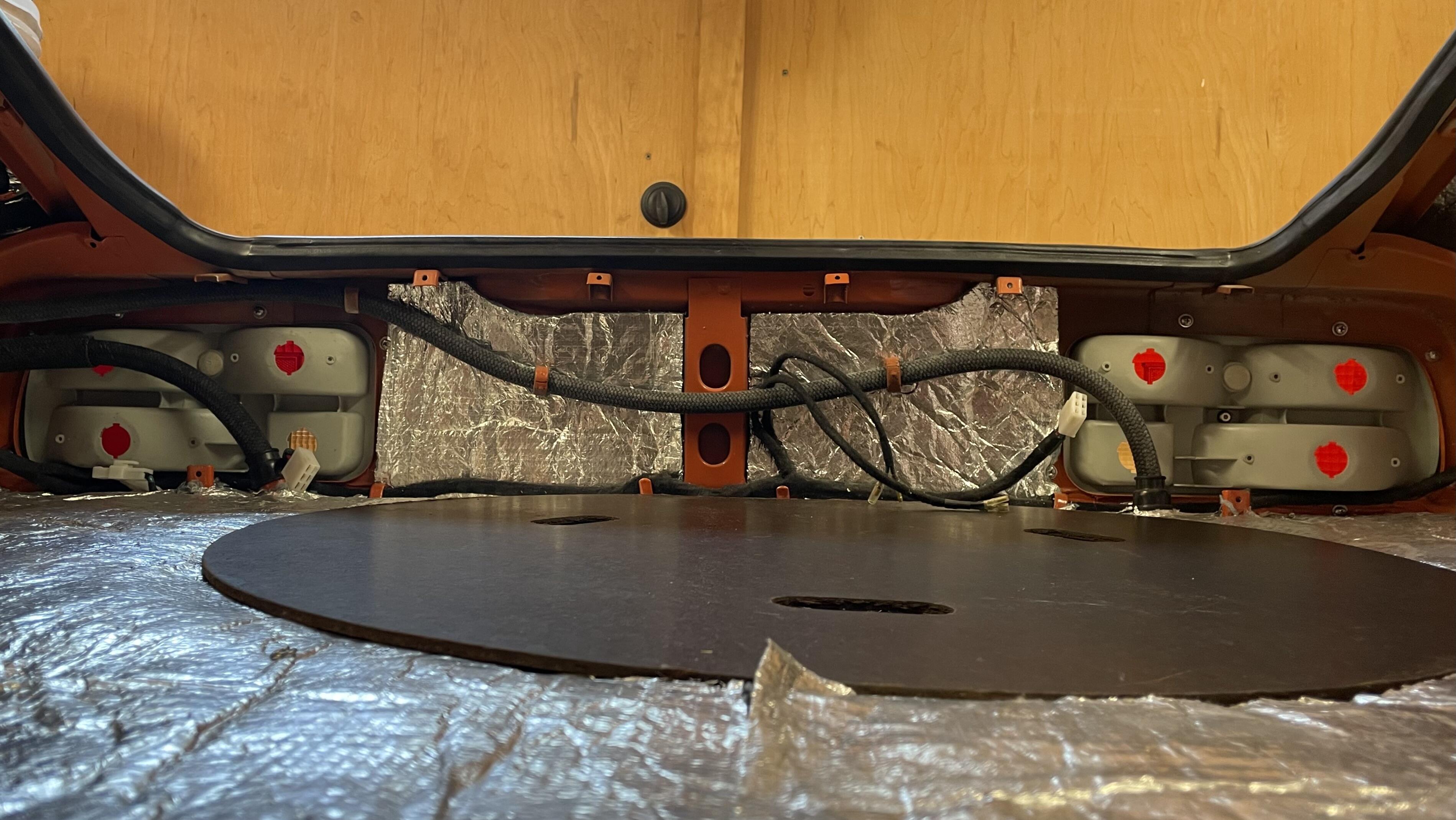
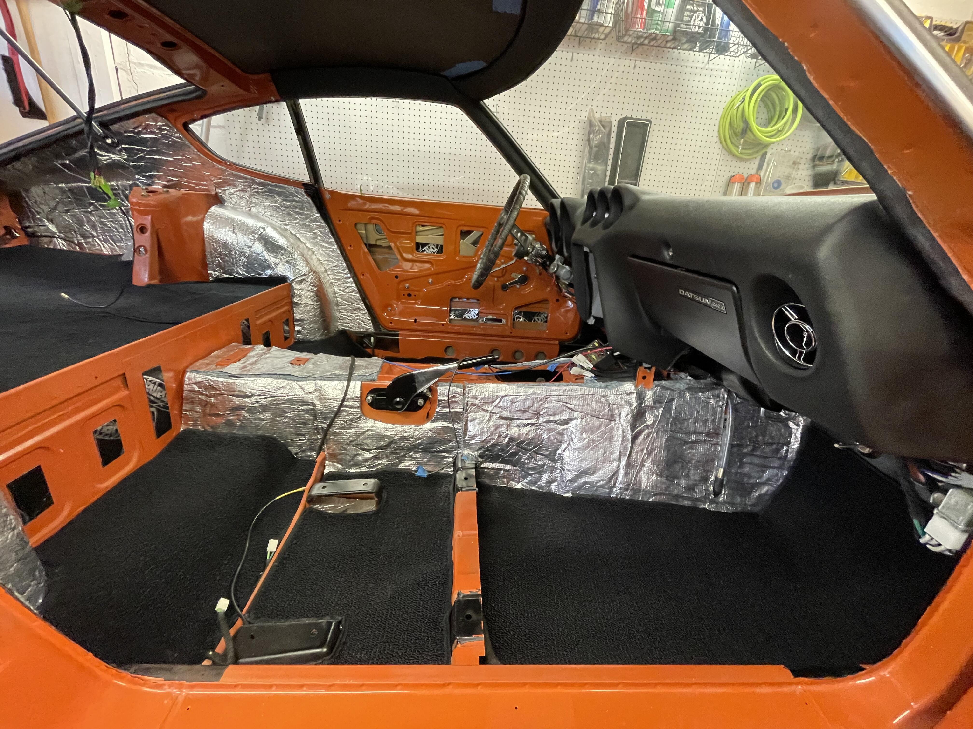
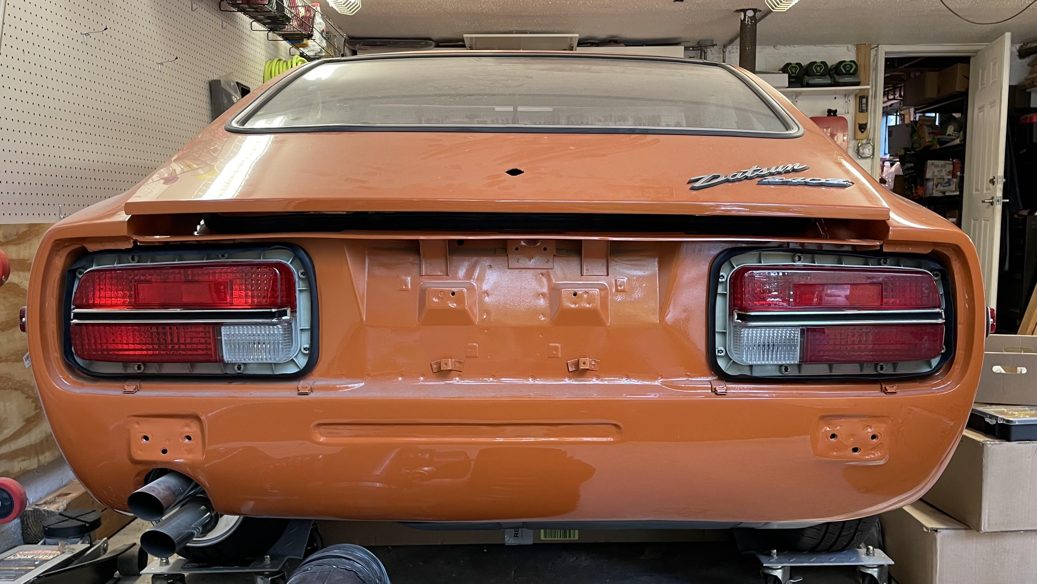
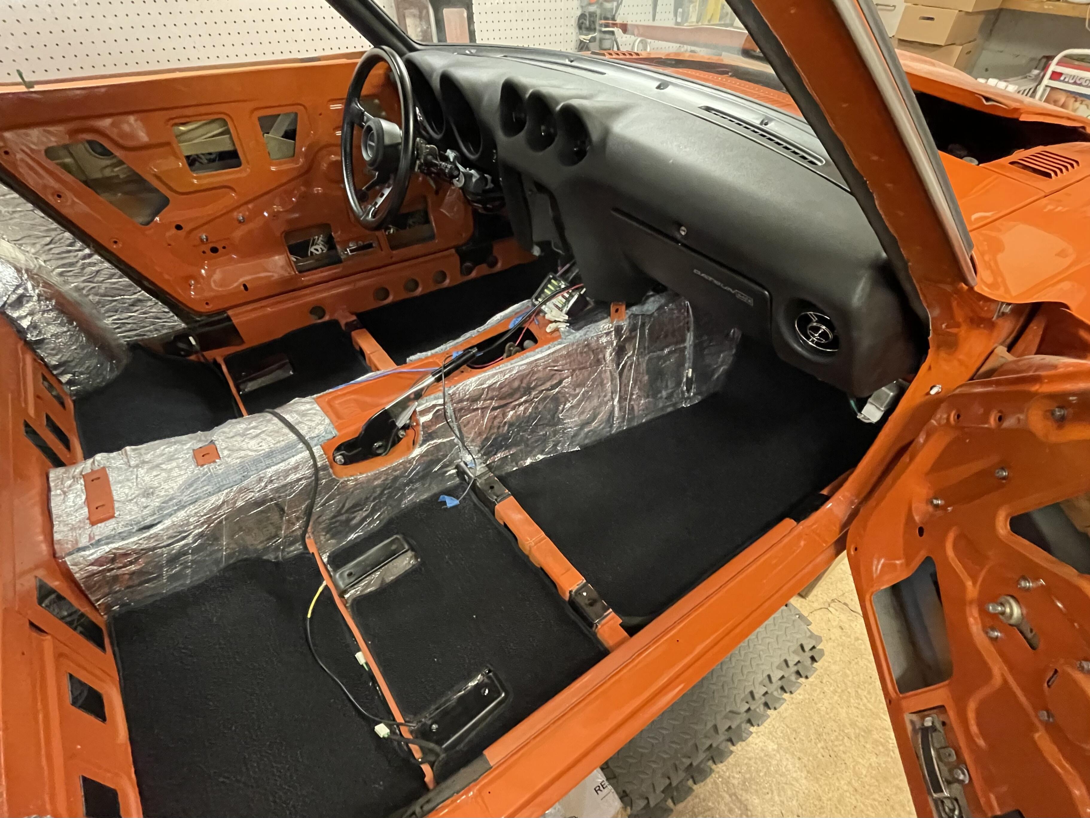
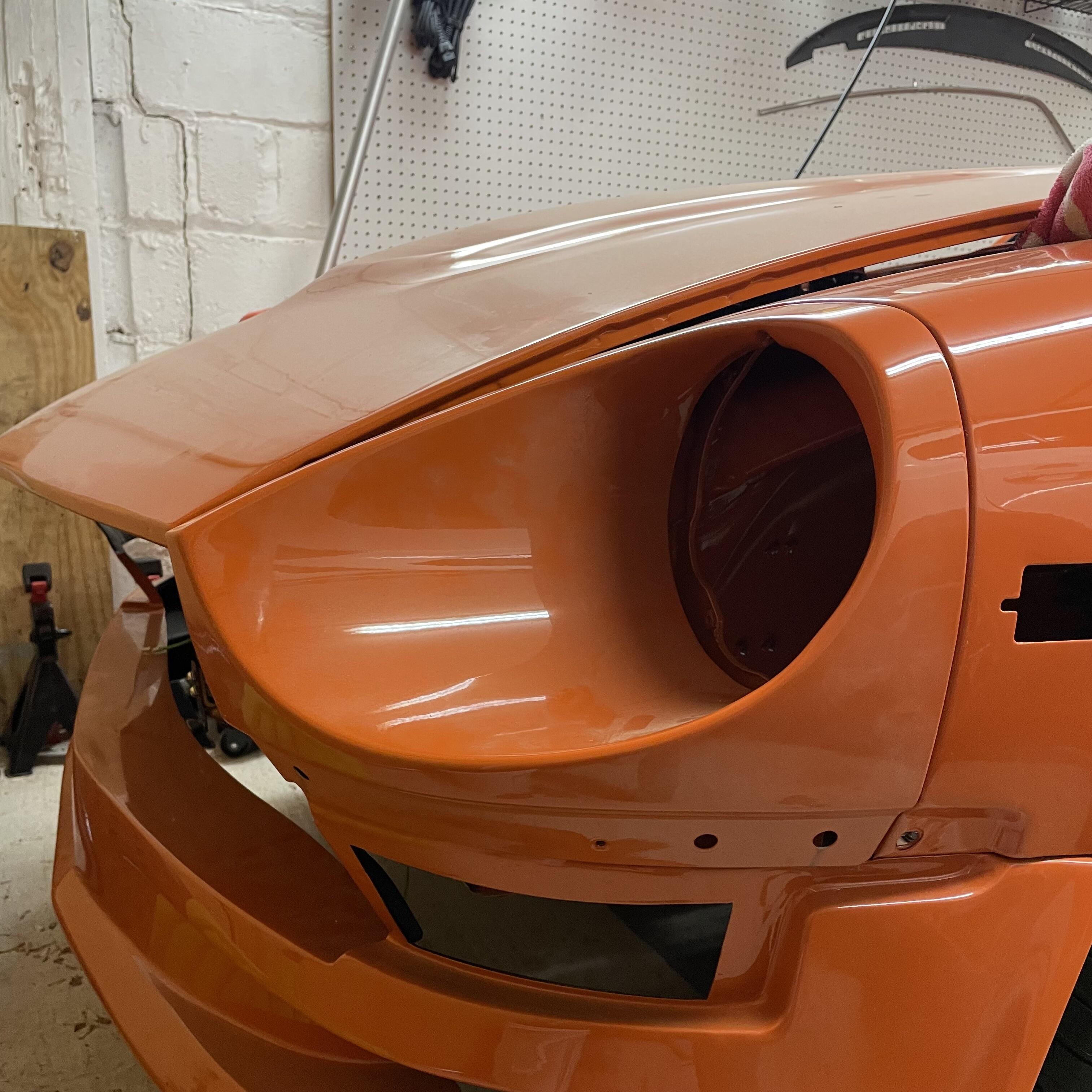
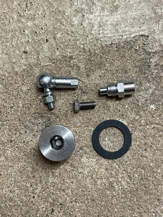
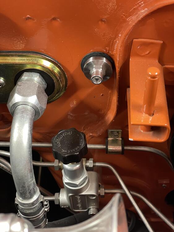
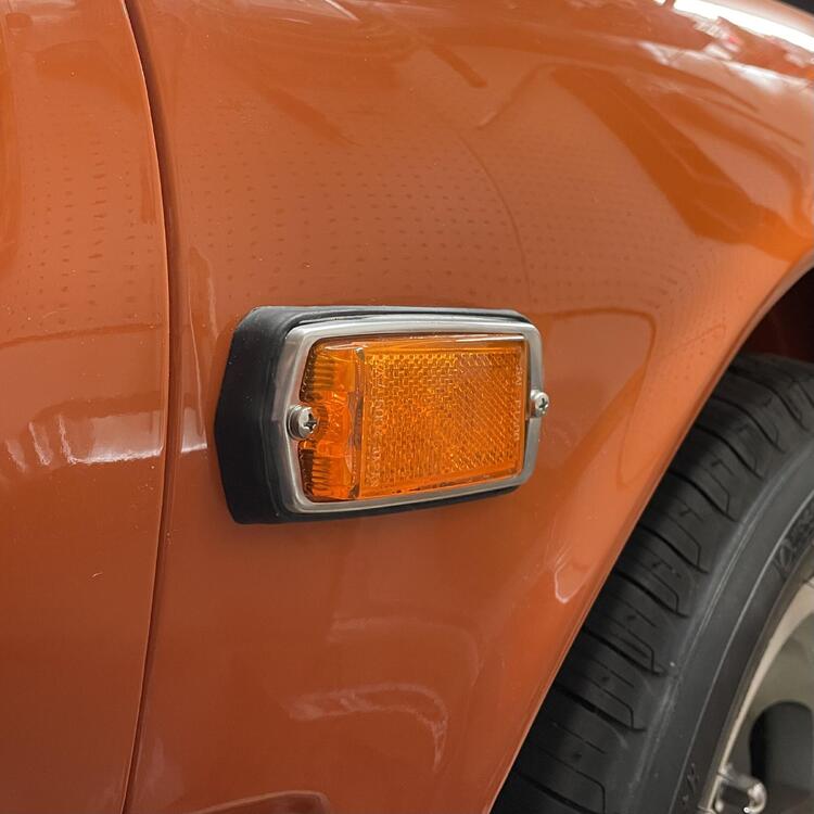
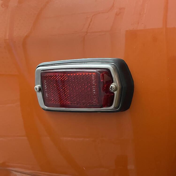
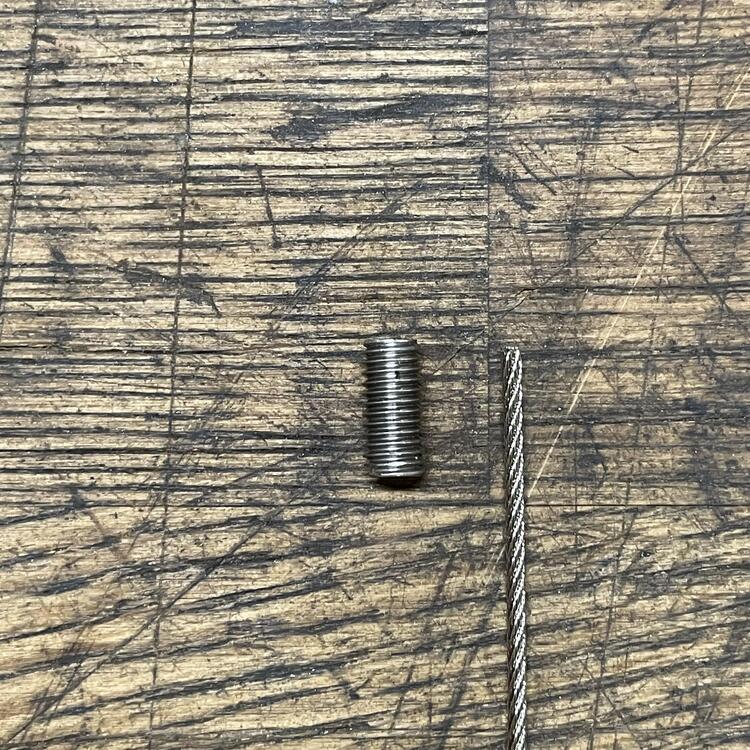
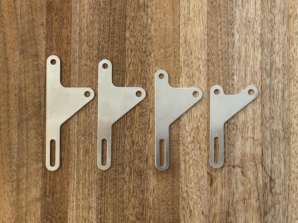
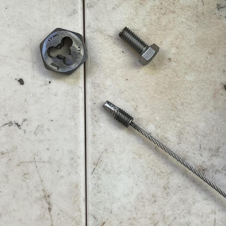
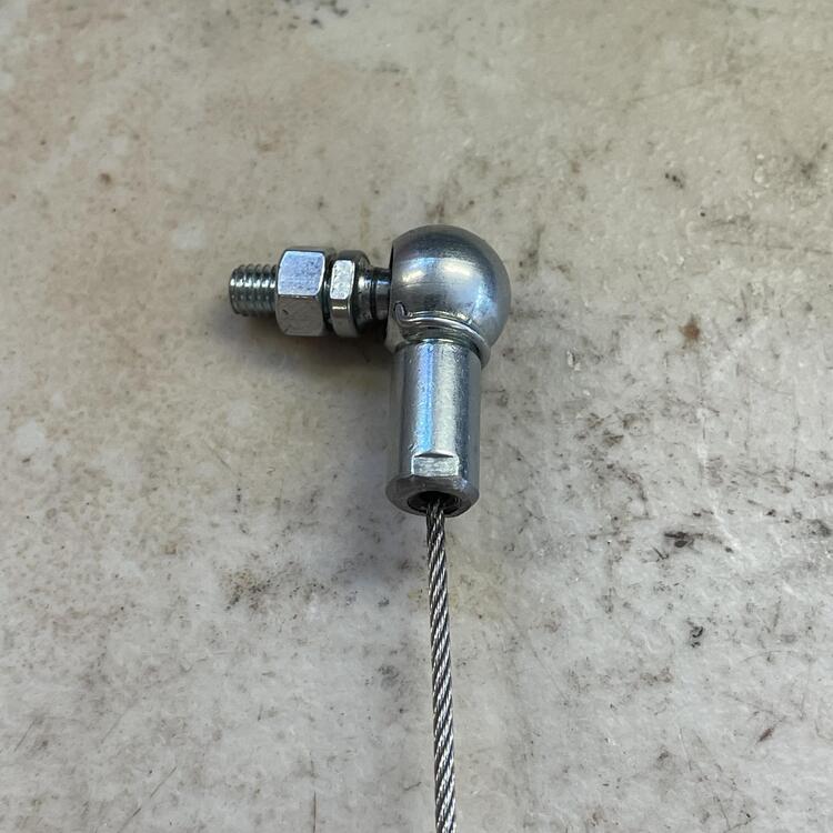
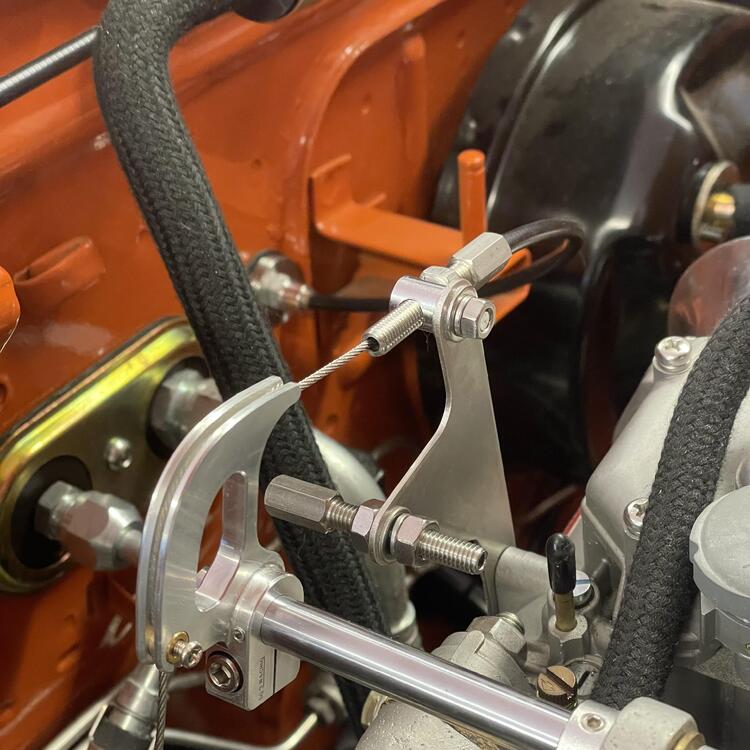
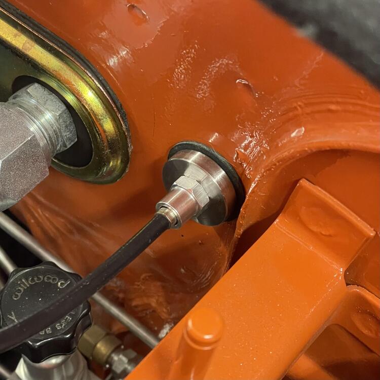
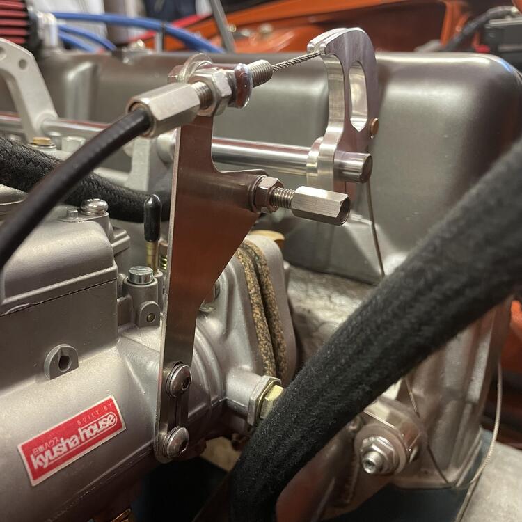
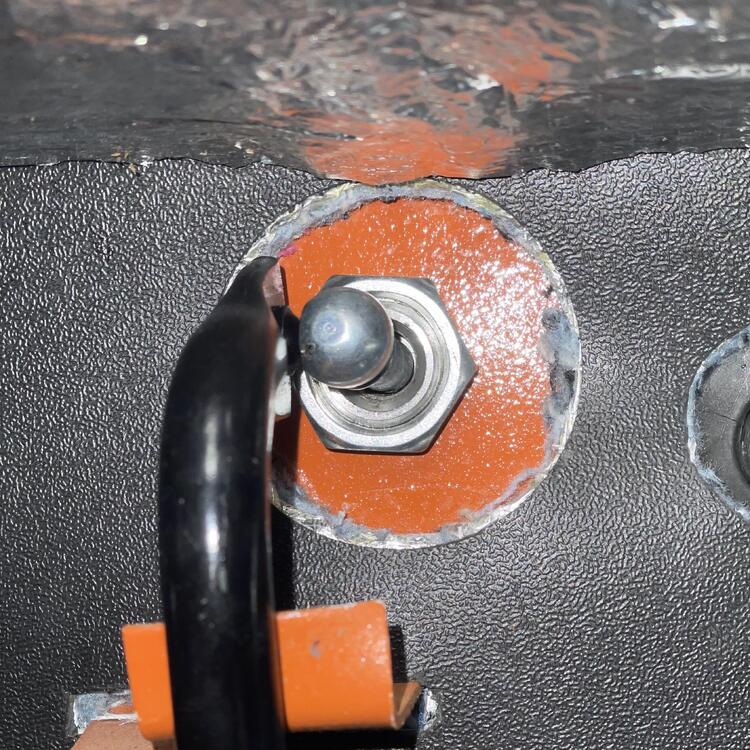
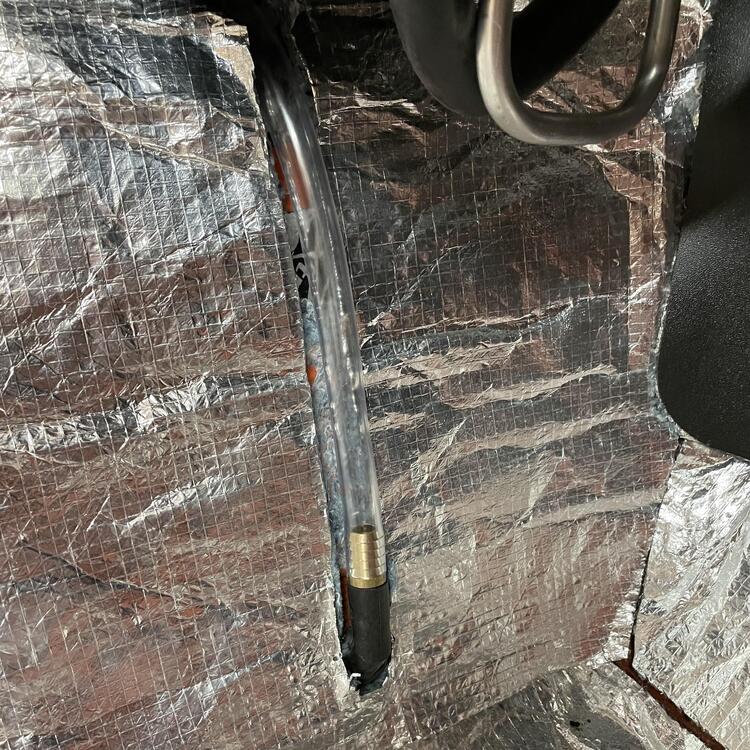
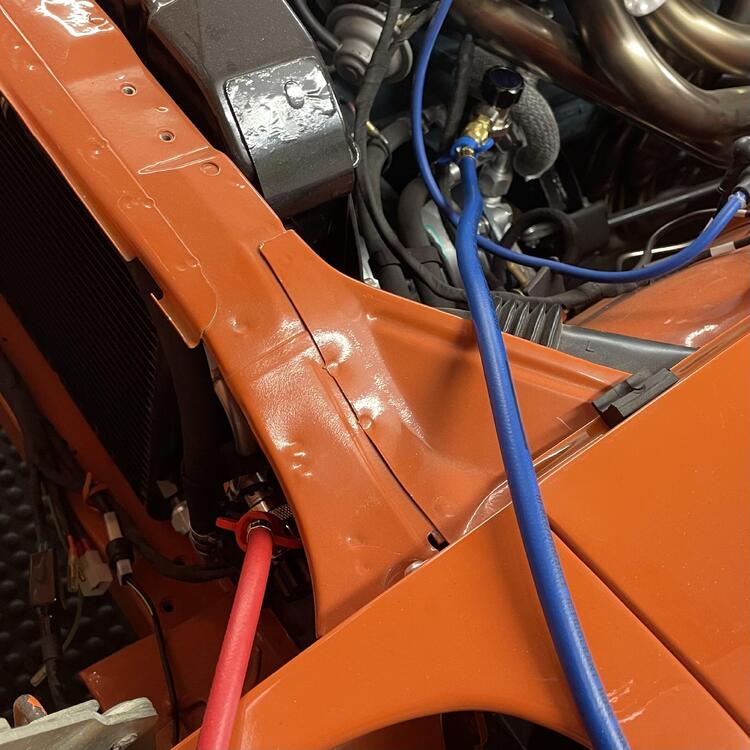
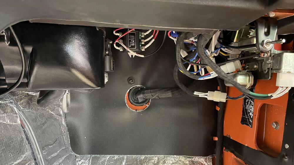
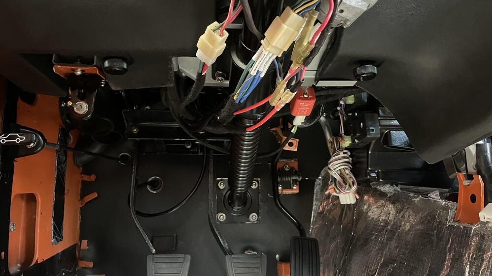
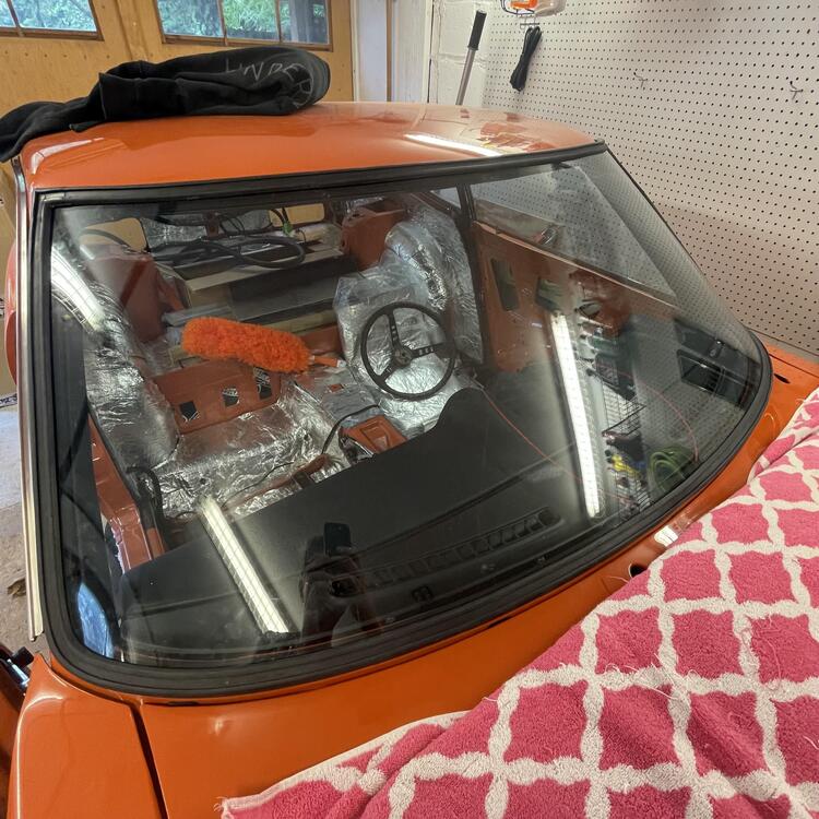
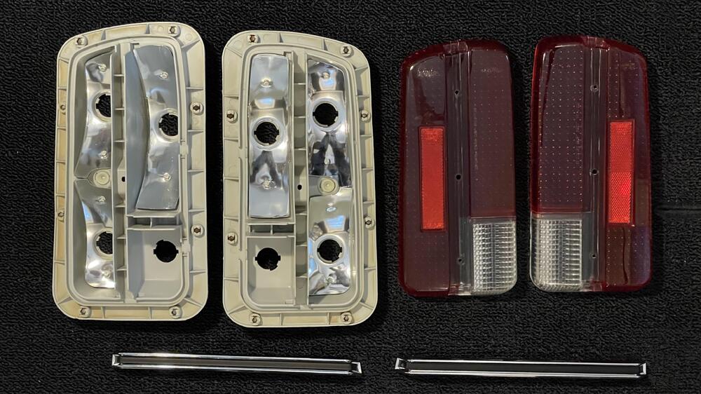
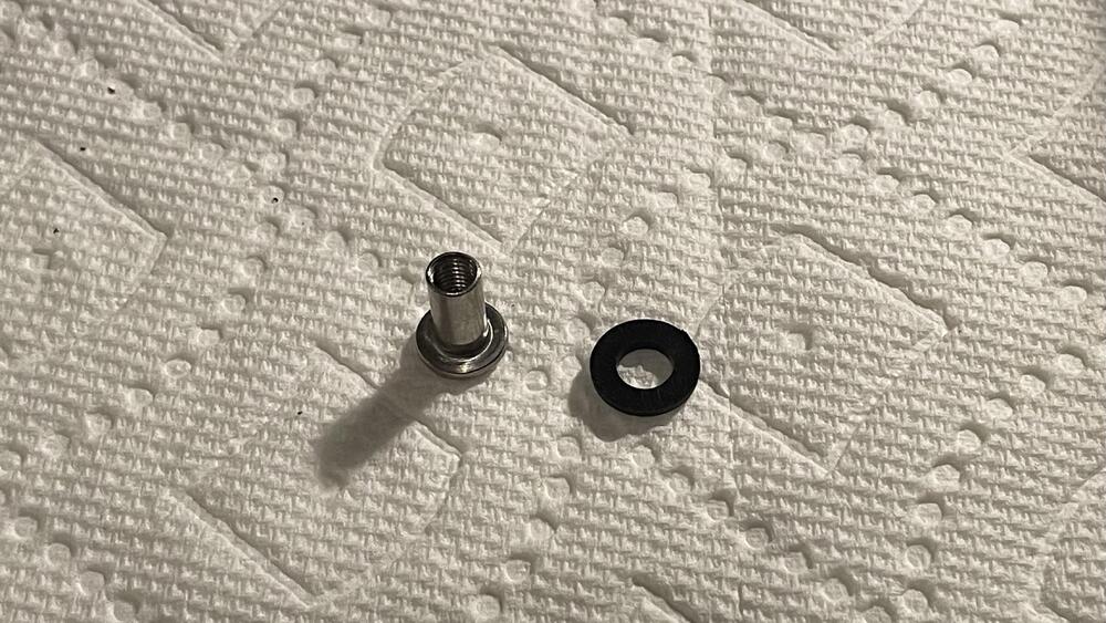
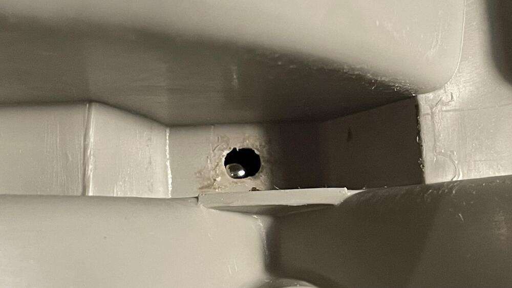
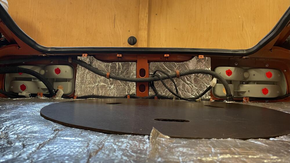
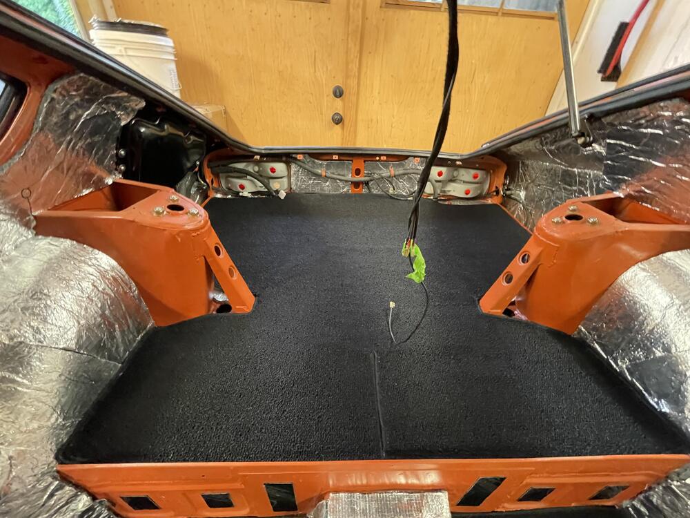
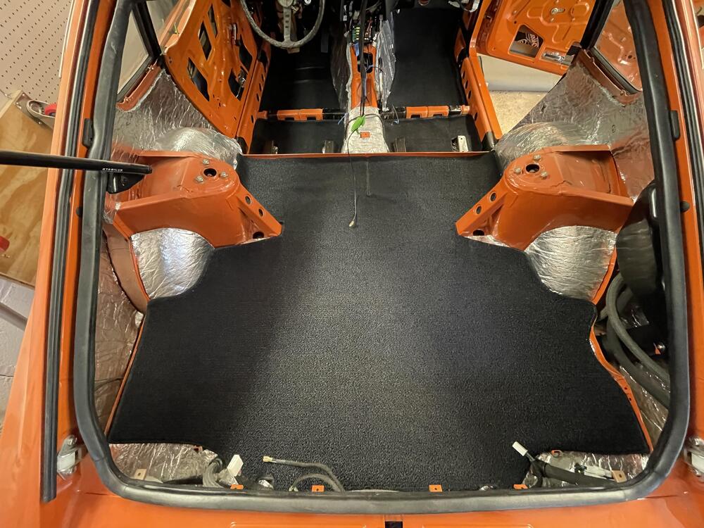
Okay, it’s been a minute so this post will be all over the place… I’m going to start with baby steps that feel like giant steps. I was able to install the left side headlight bucket last night. It seems small, but I hadn’t been able to get to all of the weatherstripping that goes under the fender so I put it off. This is the first time I’ve seen it together (on one side) since it came back from the painter. I found there was a sizable gap between the bucket and the fiberglass air dam and I didn’t know how far the dam was going to flex. It ended up working out when I got the blinkers on, but it’s not a crisp clean fit. More on that later. ••• I didn’t do a great job documenting this, but I did a complete refurb of my marker lights and turn signals, inside and out. Left side is before, right side is stage 2 of the 3 step polish. The left TS and the marker lights were pretty beat up. The plastic was nearly brown inside and the mirror and metal housings were rusted. I stripped the pieces and painted the metal parts with highly reflective silver spray paint. The plastic housing I sprayed white inside and left the outside raw. The lenses were sanded with 400 grit wet/dry paper, then up through 5,000 grit, and finally polished with Novus plastic polish. I was able to reuse all of the OEM rubber parts. They just needed scrubbing with a green scotch bright pad. I decided to replace all of the hardware with stainless. I wasn’t able to get JIS screws quickly so I just went with bolts with fender washers and nuts on the inside. I like this better anyway because the right rear screws are uncomfortably close to the fuel vapor hoses. They got rubber caps, too, just to be safe. All of the wiring and connectors were replaced. The OEM sockets and rubber boots were refurbished. I ran out of bullet connectors so I used Yamaha connectors for the front marker lights. I’m a bit bummed that the rubber connector covers for the turn signals are so short. I’m wondering if I need to do something like wrap them in tape to keep the water out. The bulbs are color specific LEDs from Super Bright LEDs, which I think look nicer than using white ones under the colored lenses. The color is much richer while still being… uh, super bright. ••• I FINALLY finished my throttle cable setup. I looked at a bunch of off the shelf options and a few specifically for Z cars, but the prices and not quite being what I wanted pushed me into making my own. The two challenging pieces were the bulkhead and the bracket. I made the bulkhead out of a stainless steel drain plug that a friend drilled out and tapped for me on his lathe. We broke a tap and probably dulled a second to the point of not being usable any more. If I did it again I would use aluminum. It’s held on with an M18 nut and has the cable adjuster for a triumph motorcycle brake lever screwed into it for the cable sleeve. That’s probably also unnecessary as I could have made the bulkhead so it acted as the cable sleeve seat on its own. The bracket was another Send Cut Send job. I had to wait until everything else was figured out to design and order it, but I made four versions with the hole for the throttle cable adjuster at various heights. I opted for the second tallest, but I’ll swap it out if this ends up feeling wrong. I went with a progressive cam from @duffymahoney and had to make sure there is no interference when said and done. The shortest bracket looked the best but was uncomfortably close to the cam at full throttle. All of the cable bits and pieces I got from Venhill Engineering for a song. The reason there are two adjusters in the photo is so the bracket can also hold the choke cable, which I am repurposing to operate the starter valves on the Mikunis. I doubt I’ll ever use them but I don’t like having inoperable parts in the car. The cable is affixed to the ball socket by a m5 lamp bolt that was decapitated, crimped to the cable, and soldered. So yeah, the throttle half of this project is done for now. I just need to change the screw holding the cable to the cam to be a set crew and cut the excess cable and cap it off. The bracket may need to be stiffer, but that’s for later. ••• Unfortunately I keep forgetting to take pictures. I DID remember with this, though, and can show you how I ran the AC drain so it minimizes the size of the lump when I install the transmission hump upholstery. The Vintage Air evaporator came with a black hose, but I swapped it out for some hose with a thicker side wall, which should keep it from compressing under the upholstery and inhibiting the flow of condensation. The black piece is from sun roof drains on GM and other vehicles and its X-shaped aperture should prevent anything from traveling back up the hose, including wind. Pretty generic and available on Amazon for a few bucks. I connected it to the hose with a 1/2” barbed splice fitting and cut the insulation to make a channel for the hose to rest in. A 5/8” hole and some RTV to make sure it doesn’t pop out and I’m good to go. Now to check the refrigerant plumbing for air leaks. I also finished the passenger side door window and the rest of the interior firewall work the same day. ••• After I was finally able to get all of the firewall work done (AC leak test and drain, a few grommets, transmission hump insulation), I put the dash in and plugged it all together. Nothing major to report since I’ve discussed the details in previous posts. This time I took more care to tuck the wiring away nicely. The few loose ends are wire for a set of foot well lights that are switched at the doors, a feed for a USB plug I intend to put in the center console, and the power/ground and control wires for the evaporator. The biggest challenge was getting it back in with the air ducts installed. This correlated tubing from Vintage Air is nice but it’s not flattened/ovular like the OEM stuff so it requires some persuading. I still think it’s better, though. It’s tough to see in the center but it’s really well fit to the evaporator without any clamps, which keeps it clean and free of things to chafe of the hose or wiring looms. I’m hoping a harness cover will clean up the wa around the relays, but I’m going to zip tie some of this up tight before any showed or covers go on. ••• Here It’s starting to feel like a car! Or, at least I am staring to get some storage space back. 🤣 I’m really pleased with how the Vintage Dashes dashboard looks. The glove box door needs adjusting, but after hitting the finisher with some SEM Products Color Coat in Landau Black, it all came together. It seems the internet was correct about that being the right color. I’d heard these aftermarket windshield gaskets leave a bit to be desired compared to OEM, and it’s true, but I think you can finesse it into shape. The gaps in the corners were really bad until I put the steel trim in. That stretched them out a bit, but it’s not perfect. I’ll let it settle for a while and then might just pump the gaps full of weather strip adhesive until it’s filled in. Speaking of trim, that’s a fun chore. 🙄 ••• My spare tire cover was FILTHY. Luckily it cleaned up well. The orange flecks in the fiber board are a nice touch. ••• Lights! No before pictures but here’s everything together. I used the same process on the lenses as the blinkers. The housings were scrubbed and then wiped lightly with acetone to get the last of the adhesive out. The center lug on the replacement chrome trim is too short to function as the only fastener holding everything together, so I used a M5 threaded socket left over from installing the blinkers along with a rubber washer. It worked fabulously, but I think it would be really easy to screw up if over tightened. No wiring yet. I just wanted to close up the cabin for the next step. ••• Clean. I picked up the basic carpet set from Newark Auto in black 80/20 loop. It’s really nicely made, but I don’t think it’s meant to go with an insulation kit like the one I have. There are a few places where it would have fit better f there was no insulation, and there are a few places where it is just straight up off. Overall give it a 89 to 91 out of 100. Worth it but could be improved. I’ll be using the vinyl kit from MSA on the sides. I’m going to cross my fingers and hope my original interior pieces clean up nicely. I just put them straight into storage without unpacking them when I bought the car, so who knows what shape their in. If they suck I’ll be new replacements. But yeah, the car is starting to feel like a car. My 10th Anniversary steering wheel really helps!


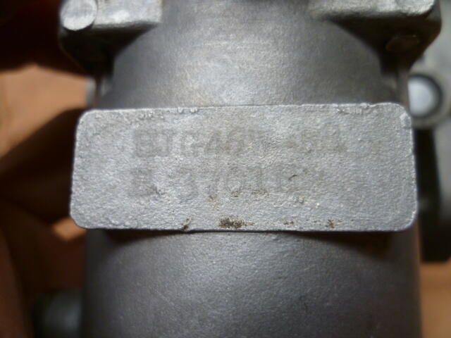
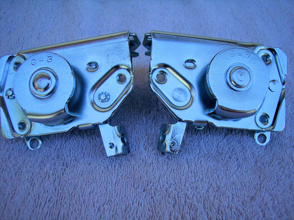
 @jfa.series1 can you tefresh me on deciphering the date codes?
 Okay, it’s been a minute so this post will be all over the place… I’m going to start with baby steps that feel like giant steps. I was able to install the left side headlight bucket last night. It seems small, but I hadn’t been able to get to all of the weatherstripping that goes under the fender so I put it off. This is the first time I’ve seen it together (on one side) since it came back from the painter. I found there was a sizable gap between the bucket and the fiberglass air dam and I didn’t know how far the dam was going to flex. It ended up working out when I got the blinkers on, but it’s not a crisp clean fit. More on that later. ••• I didn’t do a great job documenting this, but I did a complete refurb of my marker lights and turn signals, inside and out. Left side is before, right side is stage 2 of the 3 step polish. The left TS and the marker lights were pretty beat up. The plastic was nearly brown inside and the mirror and metal housings were rusted. I stripped the pieces and painted the metal parts with highly reflective silver spray paint. The plastic housing I sprayed white inside and left the outside raw. The lenses were sanded with 400 grit wet/dry paper, then up through 5,000 grit, and finally polished with Novus plastic polish. I was able to reuse all of the OEM rubber parts. They just needed scrubbing with a green scotch bright pad. I decided to replace all of the hardware with stainless. I wasn’t able to get JIS screws quickly so I just went with bolts with fender washers and nuts on the inside. I like this better anyway because the right rear screws are uncomfortably close to the fuel vapor hoses. They got rubber caps, too, just to be safe. All of the wiring and connectors were replaced. The OEM sockets and rubber boots were refurbished. I ran out of bullet connectors so I used Yamaha connectors for the front marker lights. I’m a bit bummed that the rubber connector covers for the turn signals are so short. I’m wondering if I need to do something like wrap them in tape to keep the water out. The bulbs are color specific LEDs from Super Bright LEDs, which I think look nicer than using white ones under the colored lenses. The color is much richer while still being… uh, super bright. ••• I FINALLY finished my throttle cable setup. I looked at a bunch of off the shelf options and a few specifically for Z cars, but the prices and not quite being what I wanted pushed me into making my own. The two challenging pieces were the bulkhead and the bracket. I made the bulkhead out of a stainless steel drain plug that a friend drilled out and tapped for me on his lathe. We broke a tap and probably dulled a second to the point of not being usable any more. If I did it again I would use aluminum. It’s held on with an M18 nut and has the cable adjuster for a triumph motorcycle brake lever screwed into it for the cable sleeve. That’s probably also unnecessary as I could have made the bulkhead so it acted as the cable sleeve seat on its own. The bracket was another Send Cut Send job. I had to wait until everything else was figured out to design and order it, but I made four versions with the hole for the throttle cable adjuster at various heights. I opted for the second tallest, but I’ll swap it out if this ends up feeling wrong. I went with a progressive cam from @duffymahoney and had to make sure there is no interference when said and done. The shortest bracket looked the best but was uncomfortably close to the cam at full throttle. All of the cable bits and pieces I got from Venhill Engineering for a song. The reason there are two adjusters in the photo is so the bracket can also hold the choke cable, which I am repurposing to operate the starter valves on the Mikunis. I doubt I’ll ever use them but I don’t like having inoperable parts in the car. The cable is affixed to the ball socket by a m5 lamp bolt that was decapitated, crimped to the cable, and soldered. So yeah, the throttle half of this project is done for now. I just need to change the screw holding the cable to the cam to be a set crew and cut the excess cable and cap it off. The bracket may need to be stiffer, but that’s for later. ••• Unfortunately I keep forgetting to take pictures. I DID remember with this, though, and can show you how I ran the AC drain so it minimizes the size of the lump when I install the transmission hump upholstery. The Vintage Air evaporator came with a black hose, but I swapped it out for some hose with a thicker side wall, which should keep it from compressing under the upholstery and inhibiting the flow of condensation. The black piece is from sun roof drains on GM and other vehicles and its X-shaped aperture should prevent anything from traveling back up the hose, including wind. Pretty generic and available on Amazon for a few bucks. I connected it to the hose with a 1/2” barbed splice fitting and cut the insulation to make a channel for the hose to rest in. A 5/8” hole and some RTV to make sure it doesn’t pop out and I’m good to go. Now to check the refrigerant plumbing for air leaks. I also finished the passenger side door window and the rest of the interior firewall work the same day. ••• After I was finally able to get all of the firewall work done (AC leak test and drain, a few grommets, transmission hump insulation), I put the dash in and plugged it all together. Nothing major to report since I’ve discussed the details in previous posts. This time I took more care to tuck the wiring away nicely. The few loose ends are wire for a set of foot well lights that are switched at the doors, a feed for a USB plug I intend to put in the center console, and the power/ground and control wires for the evaporator. The biggest challenge was getting it back in with the air ducts installed. This correlated tubing from Vintage Air is nice but it’s not flattened/ovular like the OEM stuff so it requires some persuading. I still think it’s better, though. It’s tough to see in the center but it’s really well fit to the evaporator without any clamps, which keeps it clean and free of things to chafe of the hose or wiring looms. I’m hoping a harness cover will clean up the wa around the relays, but I’m going to zip tie some of this up tight before any showed or covers go on. ••• Here It’s starting to feel like a car! Or, at least I am staring to get some storage space back. 🤣 I’m really pleased with how the Vintage Dashes dashboard looks. The glove box door needs adjusting, but after hitting the finisher with some SEM Products Color Coat in Landau Black, it all came together. It seems the internet was correct about that being the right color. I’d heard these aftermarket windshield gaskets leave a bit to be desired compared to OEM, and it’s true, but I think you can finesse it into shape. The gaps in the corners were really bad until I put the steel trim in. That stretched them out a bit, but it’s not perfect. I’ll let it settle for a while and then might just pump the gaps full of weather strip adhesive until it’s filled in. Speaking of trim, that’s a fun chore. 🙄 ••• My spare tire cover was FILTHY. Luckily it cleaned up well. The orange flecks in the fiber board are a nice touch. ••• Lights! No before pictures but here’s everything together. I used the same process on the lenses as the blinkers. The housings were scrubbed and then wiped lightly with acetone to get the last of the adhesive out. The center lug on the replacement chrome trim is too short to function as the only fastener holding everything together, so I used a M5 threaded socket left over from installing the blinkers along with a rubber washer. It worked fabulously, but I think it would be really easy to screw up if over tightened. No wiring yet. I just wanted to close up the cabin for the next step. ••• Clean. I picked up the basic carpet set from Newark Auto in black 80/20 loop. It’s really nicely made, but I don’t think it’s meant to go with an insulation kit like the one I have. There are a few places where it would have fit better f there was no insulation, and there are a few places where it is just straight up off. Overall give it a 89 to 91 out of 100. Worth it but could be improved. I’ll be using the vinyl kit from MSA on the sides. I’m going to cross my fingers and hope my original interior pieces clean up nicely. I just put them straight into storage without unpacking them when I bought the car, so who knows what shape their in. If they suck I’ll be new replacements. But yeah, the car is starting to feel like a car. My 10th Anniversary steering wheel really helps!


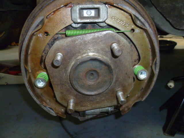
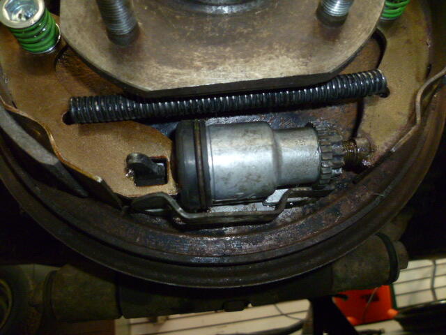
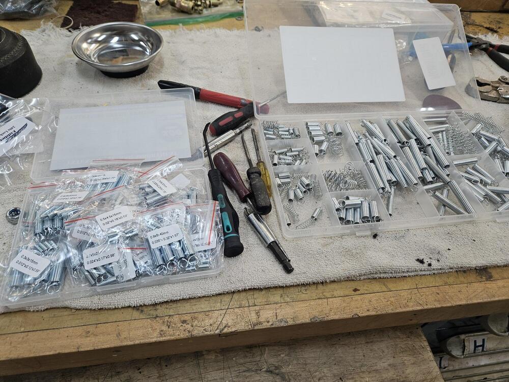
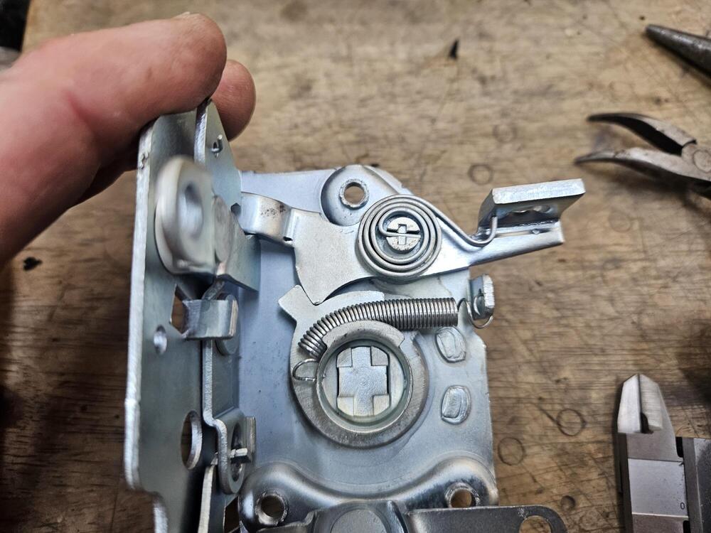
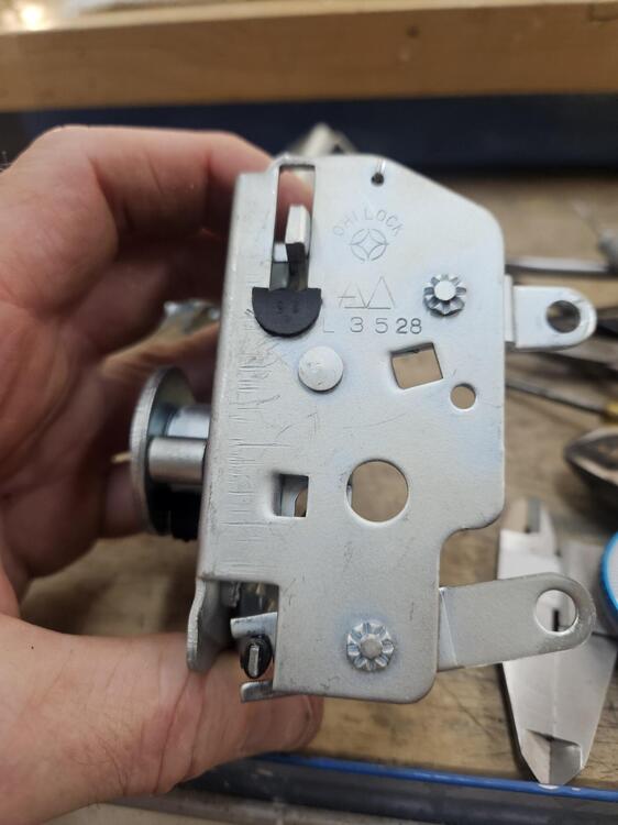
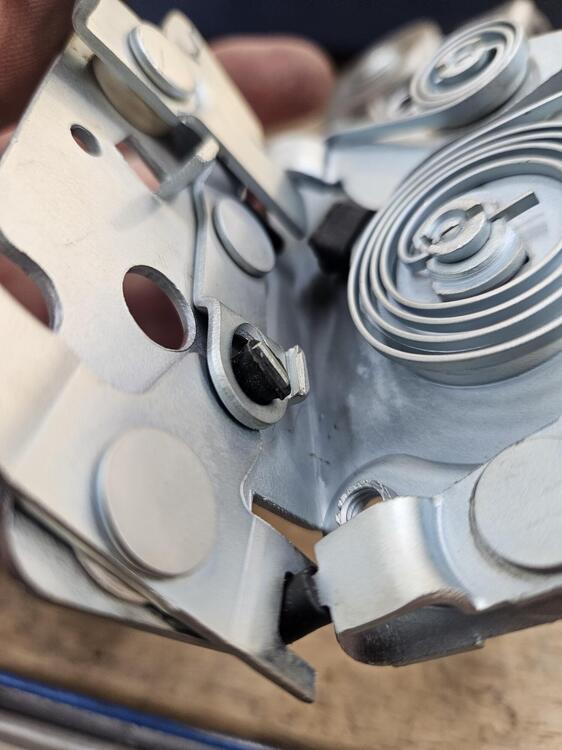
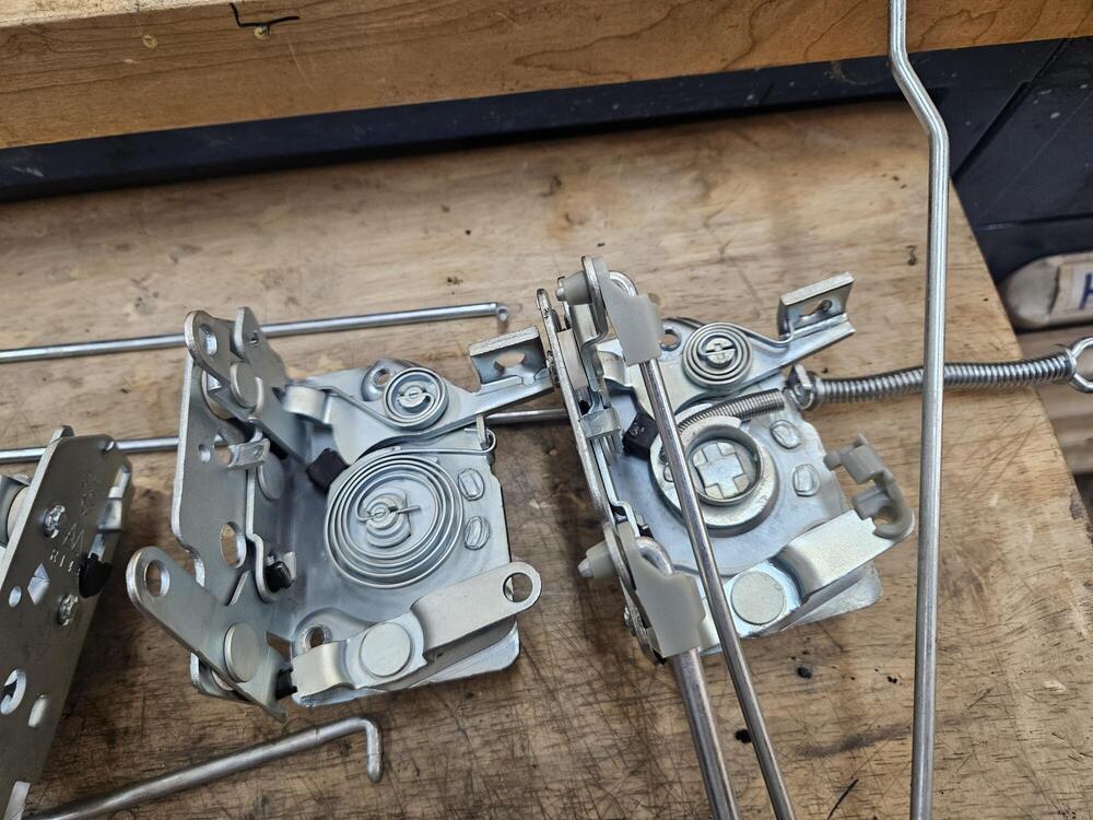
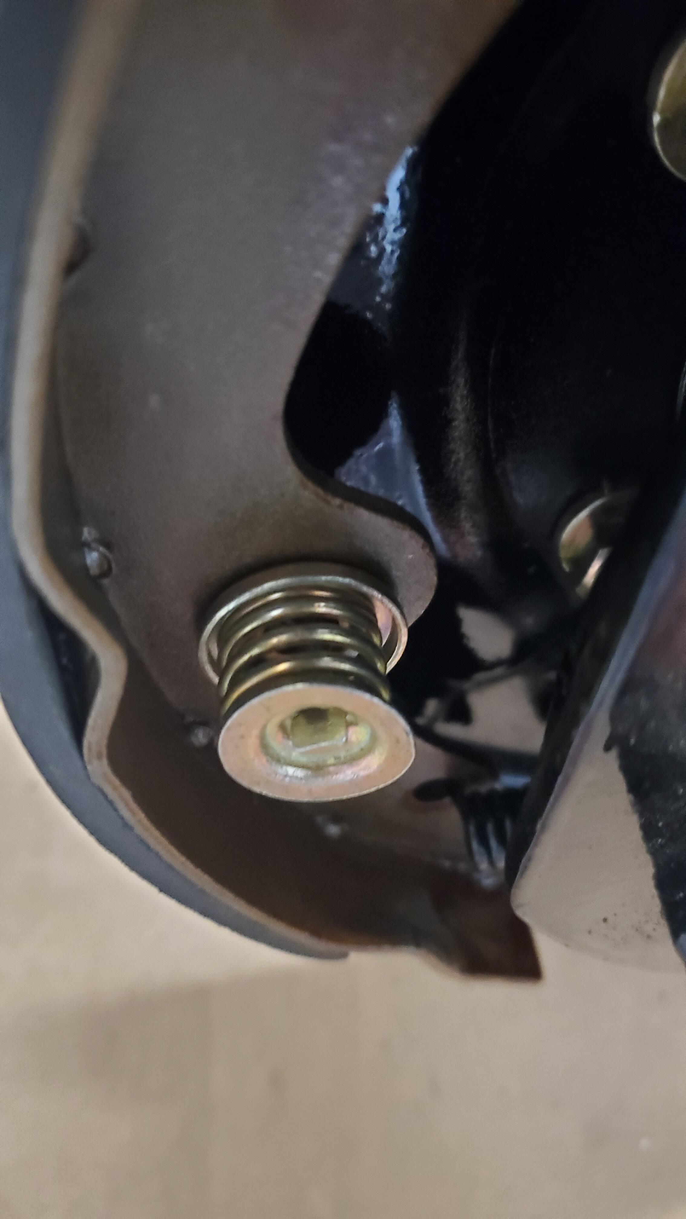
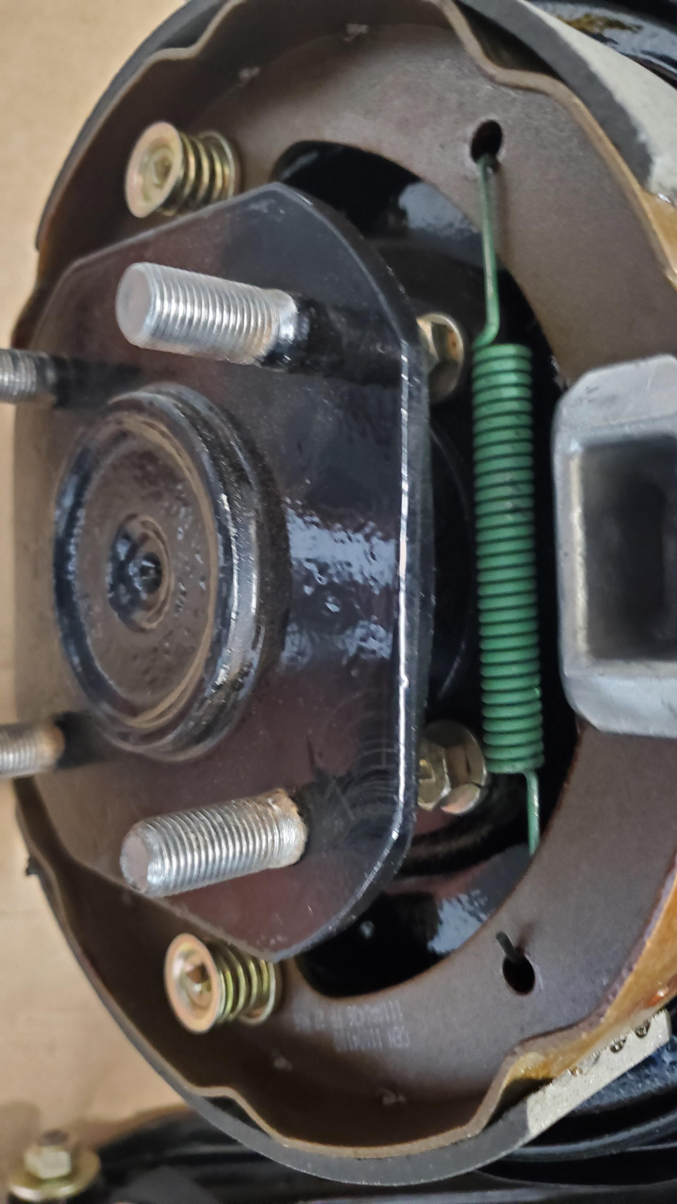
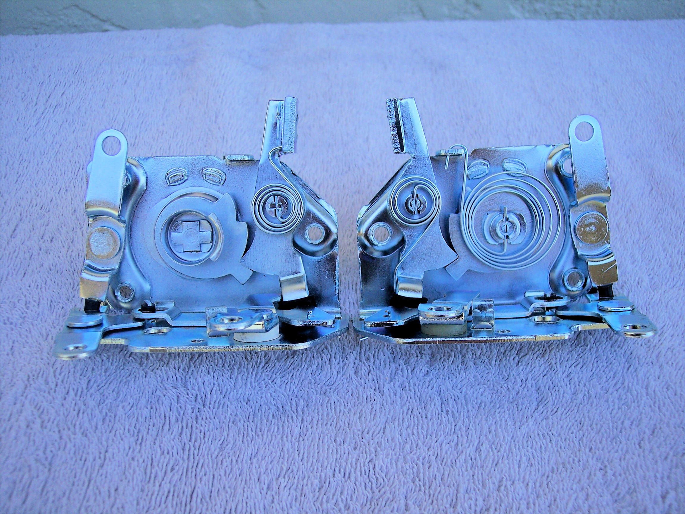
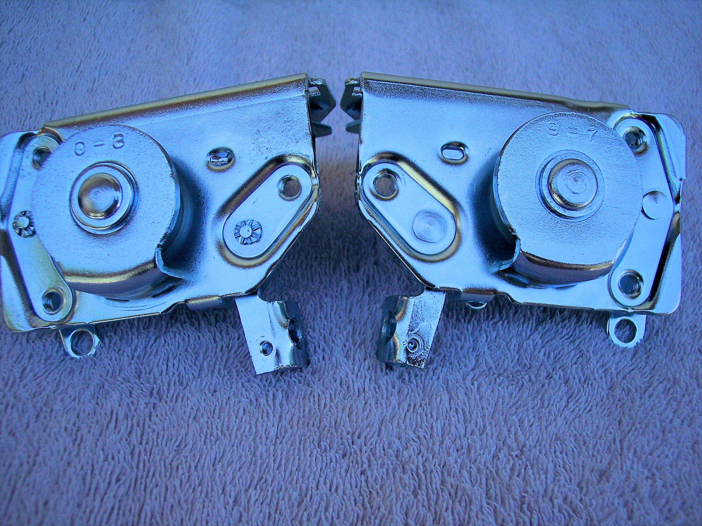
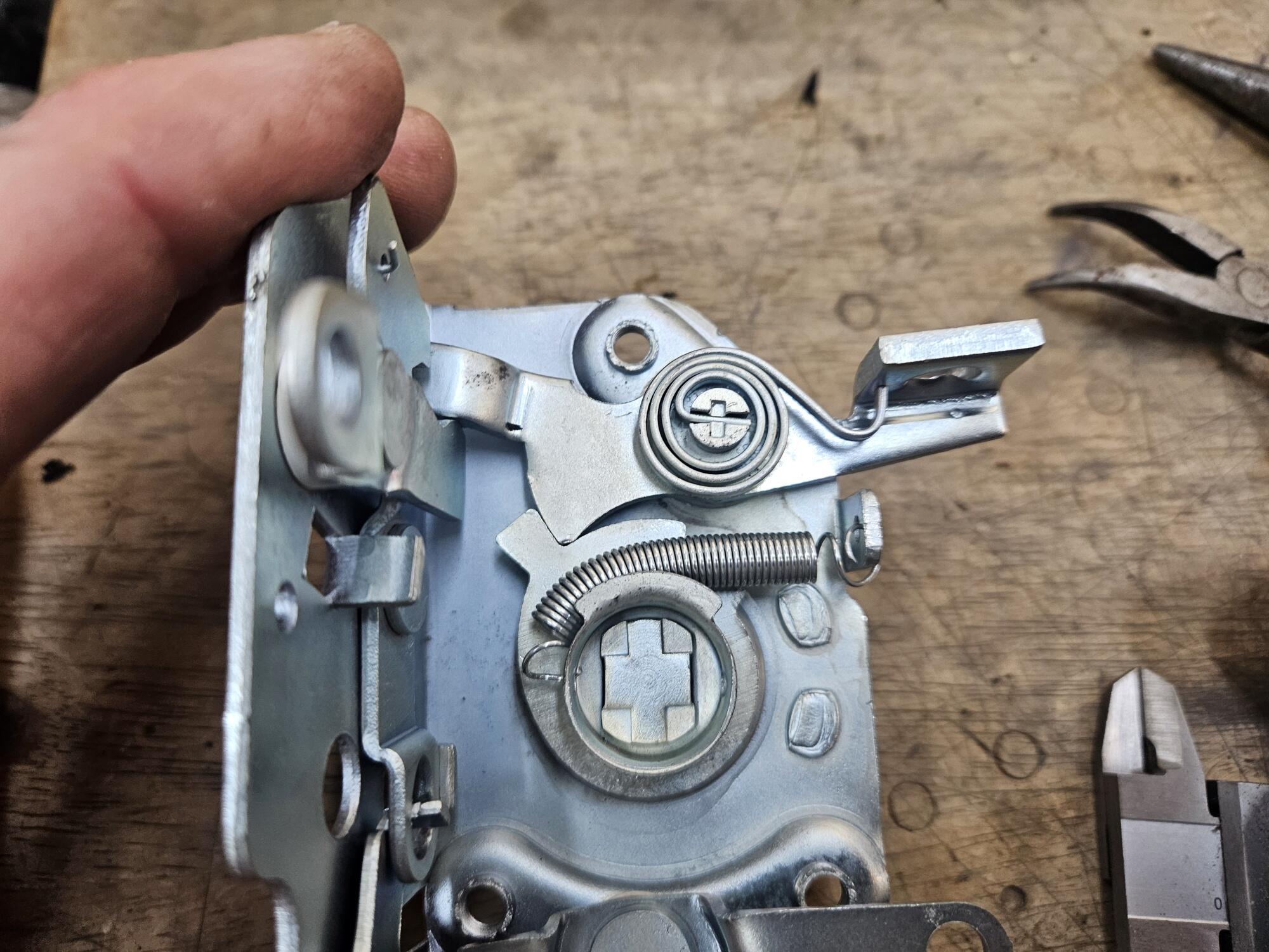
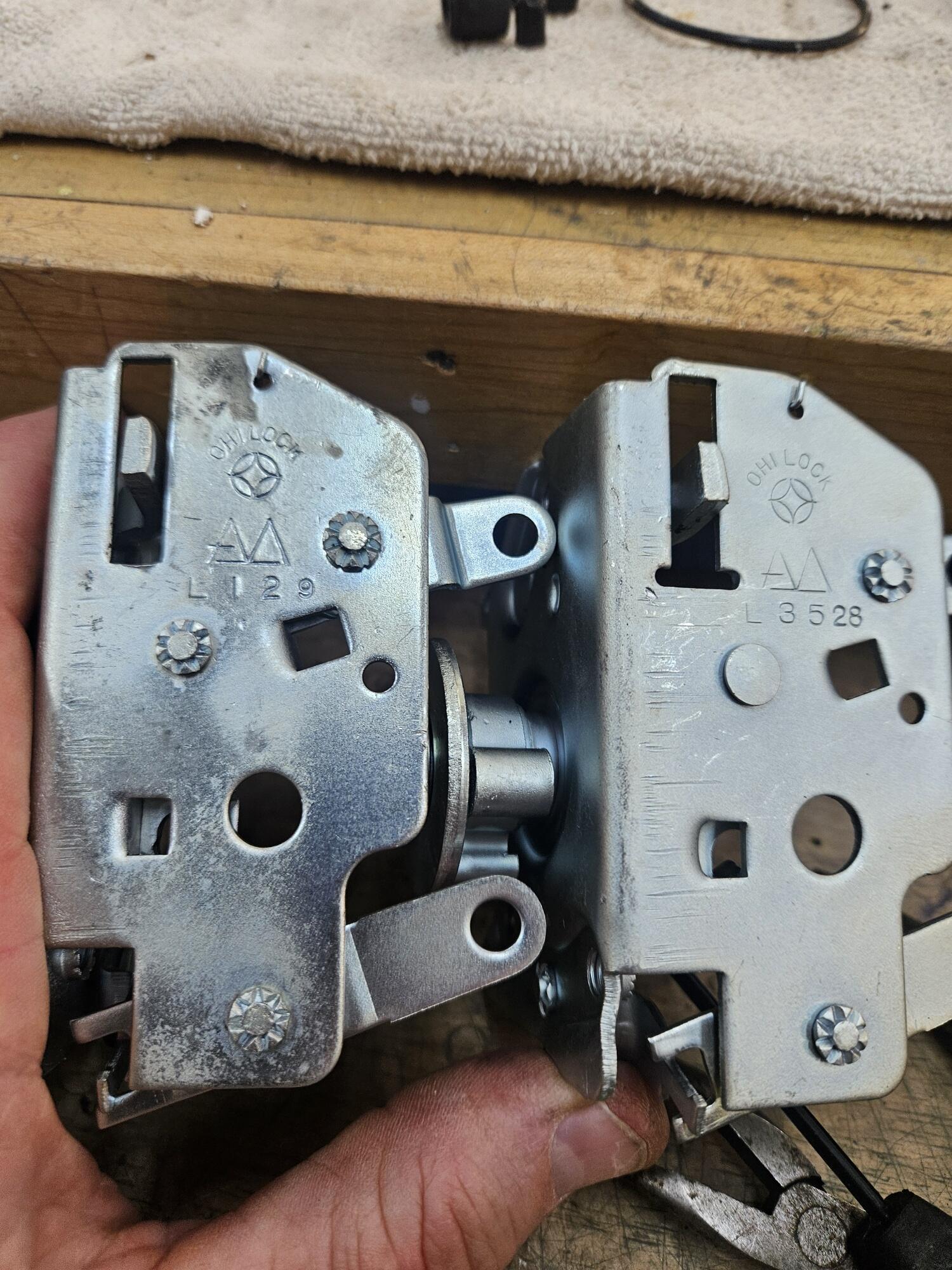
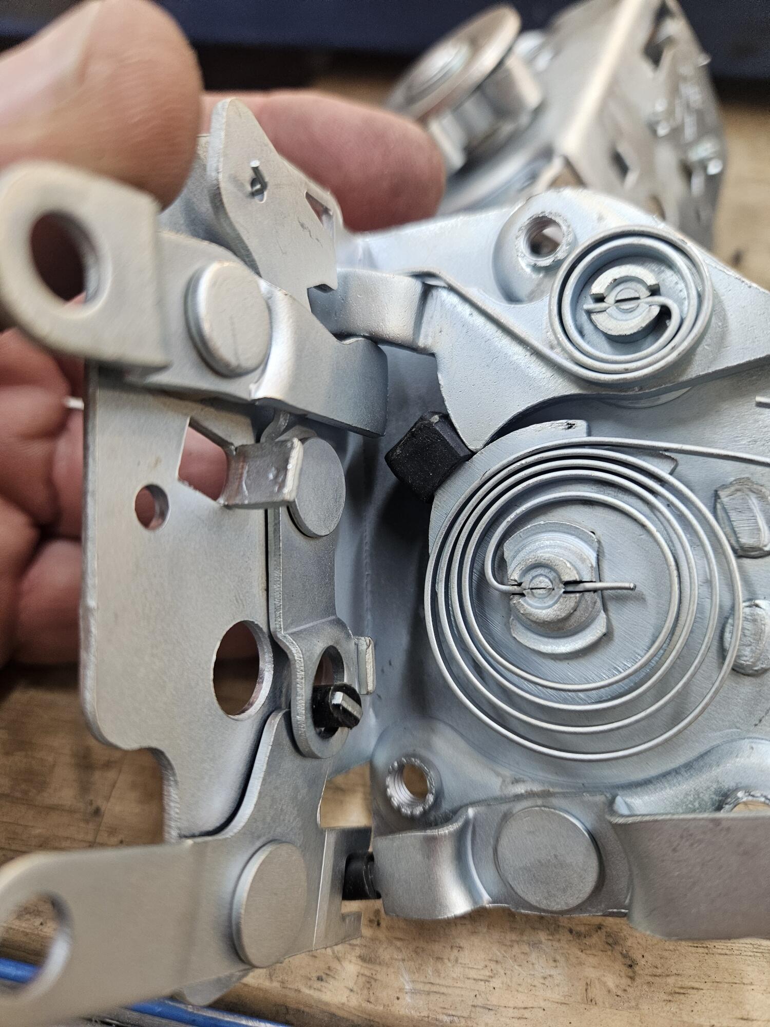
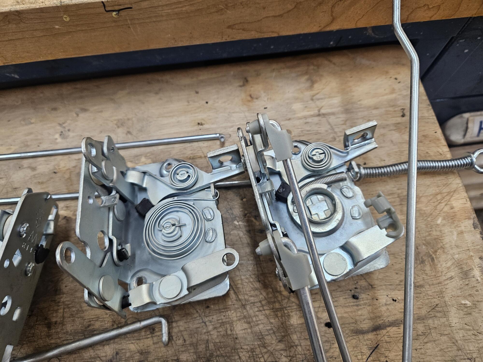
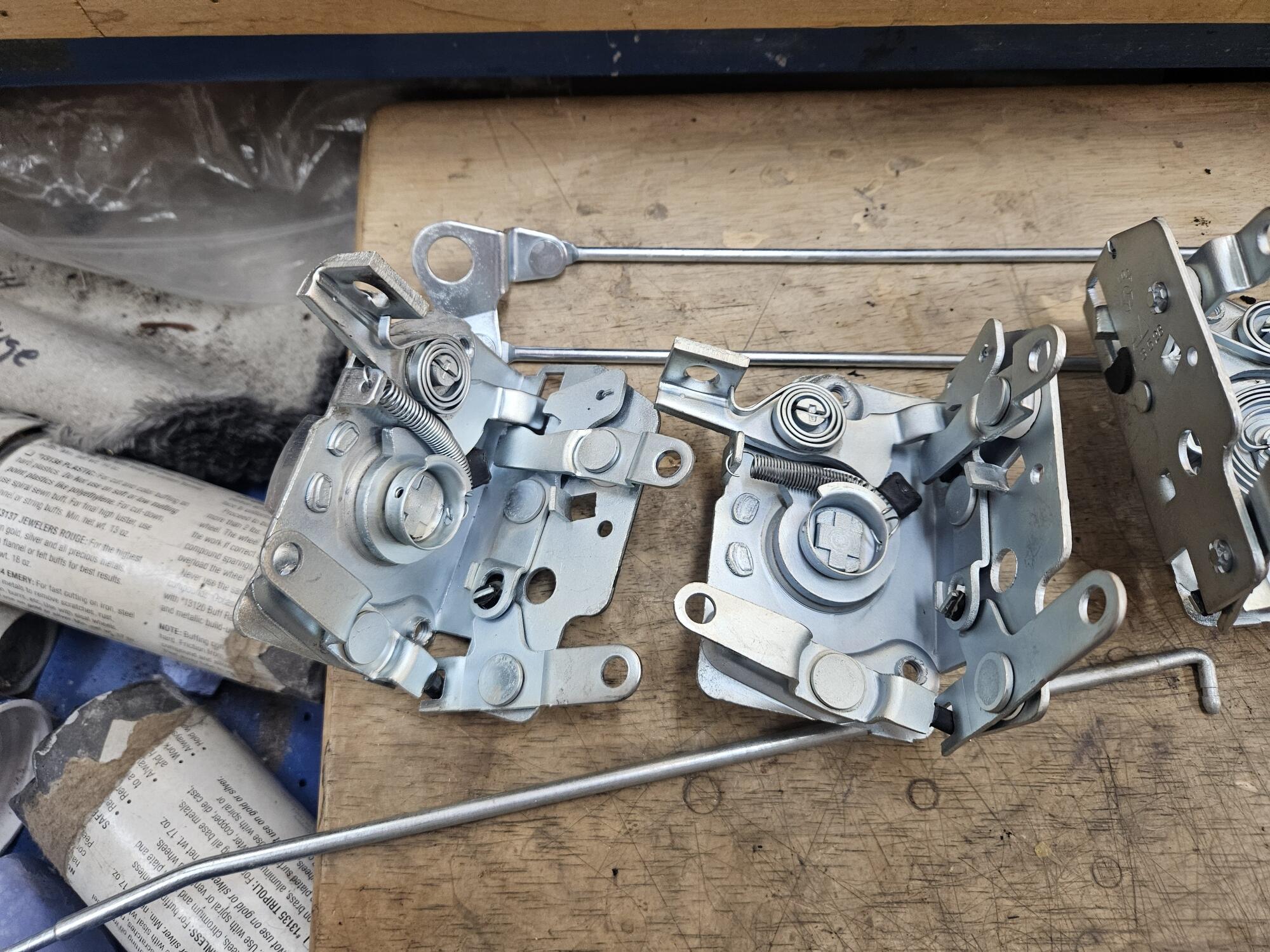
 Brake shoe hold down retainer spring pics

 I get that info later this week when returning home from a business trip.
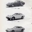 What are the window dates?
 I'm not sure it it made it the resources. Look for the thread titled 1970 Wiring Diagram in the electrical forum. Go to the May 1 post to get the download able PDF
 I have not. Is that in a files/resources section of the website?
 http://www.zcarblog.com/wp-content/uploads/2023/06/IMG_5209-1024x768.jpeg Join us on Sunday, June 8 for the Z Owners of Northern California (ZONC) gathering at the Blackhawk Museum! See flyer below for more details: http://www.zcarblog.com/wp-content/uploads/2025/05/499860045_10236740117827575_7586398421903317342_n-scaled.jpg We had a blast at last year’s ZONC event with a fantastic turnout. See our report from the 2023 event HERE, and Z you at Blackhawk! http://www.zcarblog.com/wp-content/uploads/2023/06/IMG_5176-1024x768.jpeghttp://www.zcarblog.com/wp-content/uploads/2023/06/IMG_5284-1024x768.jpeg http://www.zcarblog.com/wp-content/uploads/2023/06/IMG_5194-1024x768.jpeghttp://www.zcarblog.com/wp-content/uploads/2023/06/IMG_5250-1024x768.jpeg View the full article
 andy19422 joined the community
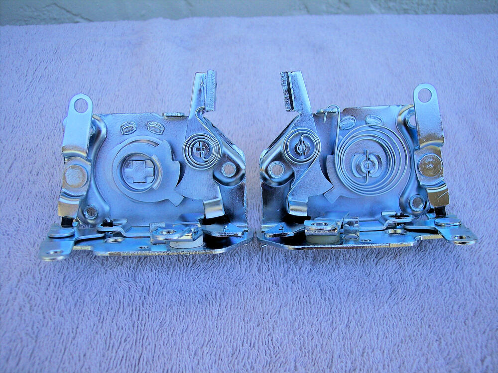
 Here's a good read on installation for a '72. Dave's 1972 Datsun 240z: Electri...Electric Fuel Pump InstallationIn an effort to make the 240z more reliable, I've decided to upgrade to an electric fuel pump and then retire the mechanical pump. By using...
 The oil pressure switch on the 78 280 was the only model that had that configuration.
 Logybeara joined the community
 You could do an inertia switch in the jumper loop on that plug. Duralast Fuel Pump Inertia Switch SW1771
 jimmyd joined the community
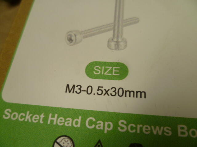
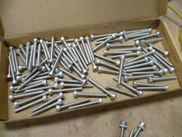
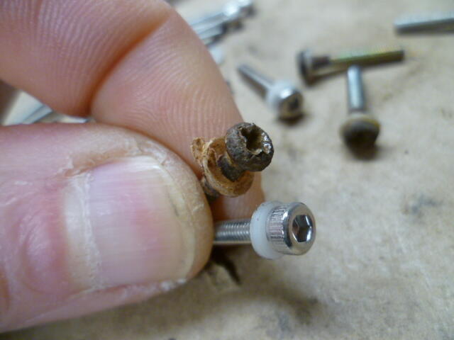
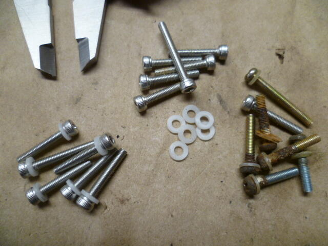
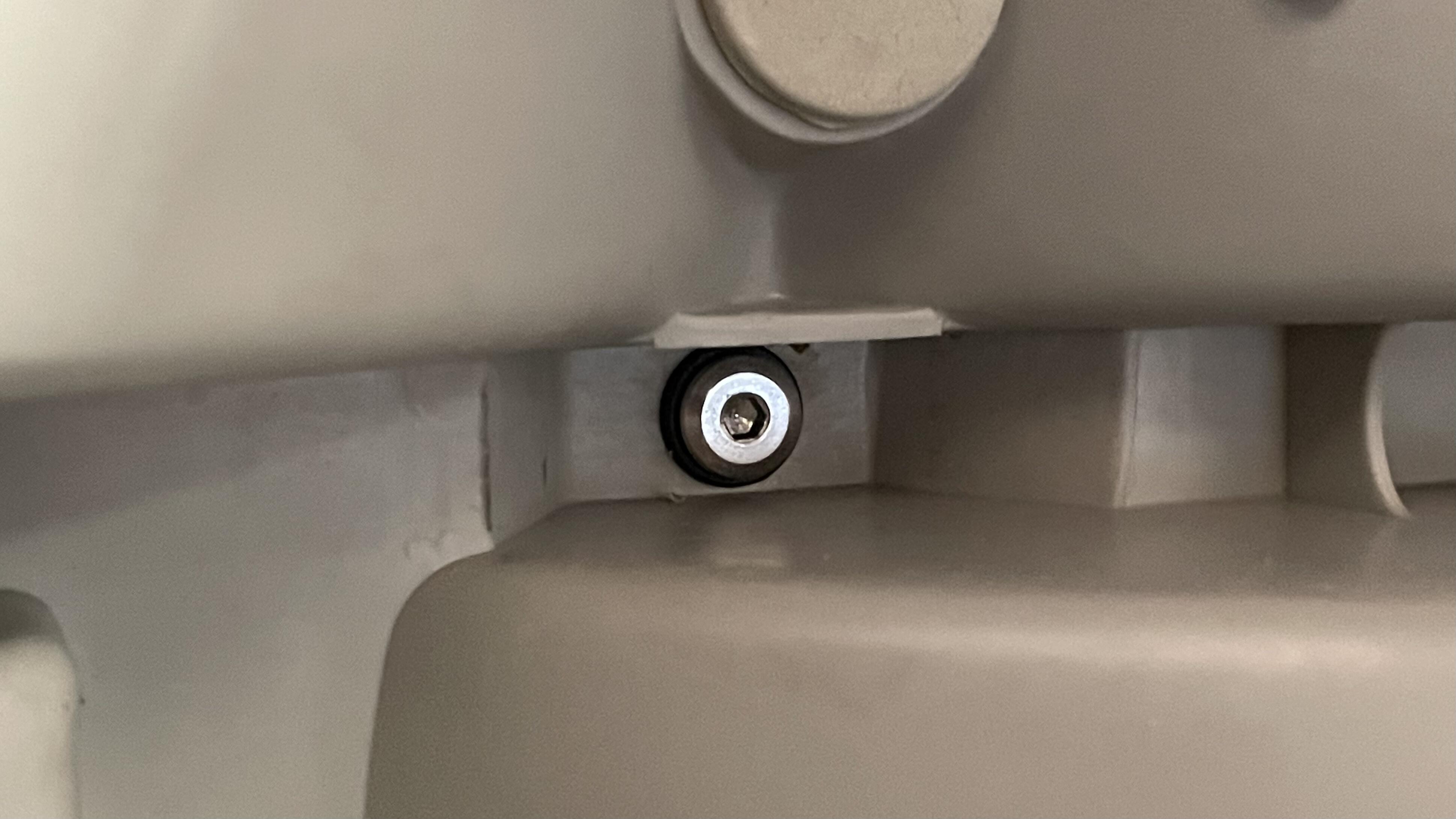
 Yeah, I went socket head because I was thinking that getting in there with a hex driver would be easier than a phillips screw driver. And now that I've done it, I think I made the right call. T-handle allen driver for the win. Oh, and they're stainless. Seemed like the right material for the application.
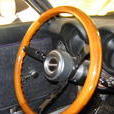 Yeah i know thát feeling.. it was only yesterday that i took a look at a combination of a drill/lathe and millingmachine.. but not really to buy one because it's all Chinese junk and i don't have really room for it/that! (And a bridgeport is a machine that needs a stable floor!)
 They look like the radio power and lighting connections. Does you car have a radio installed?