All Activity
- Yesterday
-
 Not sure that’s appropriate to the vendor for not stating the issues involved. IMO
 -
 The next best thing to a 240-Z. Bring a TrailerBobby Rahal's 1967 Toyota 2000GTBid for the chance to own a Bobby Rahal’s 1967 Toyota 2000GT at auction with Bring a Trailer, the home of the best vintage and classic cars online. Lot #224,826.
 -
 I like your comment. “It’s part of the game” I bought the car from my neighbor around the corner less than a mile away drove it around the block and then home then started taking things apart. So really I have no idea if it’s a good functional distributor or not.🙂
 -
 The other thing that often fails on the old distributors is the bearing mechanism under the vacuum advance breaker plate. The bearings and the surface get rusty, the balls stick, and the plastic cage breaks. Most people probably don't notice (I didn't) because it just stops the vacuum advance timing adjustment from working. Here's some instructions showing what's in there. The main difference would be points instead of electronics on top. https://www.atlanticz.ca/zclub/techtips/distributorrebuild/index.html If you have a good functional distributor then a Pertronix unit might be a good choice. If your distributor is gummed up, maybe look around for other options. It's all part of the game.
 -
I clamped my distributor in the vice this morning tried to get play side to side couldn't feel any movement it goes up and down slightly but that's probably normal. Anyway, I think I like the idea of a new distributor 54 years old there's no way around that
-
 Well if you think the steering is heavy with the 195 width the 205 should be heavier and the ride will be somewhat rougher. My thinking on tires for these older cars that haven't been modified is mixed. If you want to experience the drivability that Datsun intended you should stick to the original size as closely as possible. That's important to some, not to others. In todays market this really limits the availability of the tires and there in lies another issue. I too have an unmodified Z and just ordered some new wheels and tires for it. Based on tires available I ended up going with a 16" Panasports and 205/55 ultra high performance all-season tires. Nothing crazy but it should tighten up the response some without sacrificing all of the true Z feel. I know this last paragraph doesn't answer your question, just food for thought. Good luck!
 -
 After reading some horror reviews about this vendor I thought I'd post here - any vendor links elsewhere are greatly appreciated! https://rspeccarbon.com/products/front-airdam-s130-280zx
 -
 Yes! I had a long time ago a 280zx, and it kept going out of 5th gear when decellerating. i lengtened the spring (by a few mm) of the 5th gear and the problem was solved! You live in Germany, i live in Limburg near the border of Germany! If i go 2 km to the east i'm in Germany! (Kreis Kleve!) Maybe your in the neighberhood?
 -
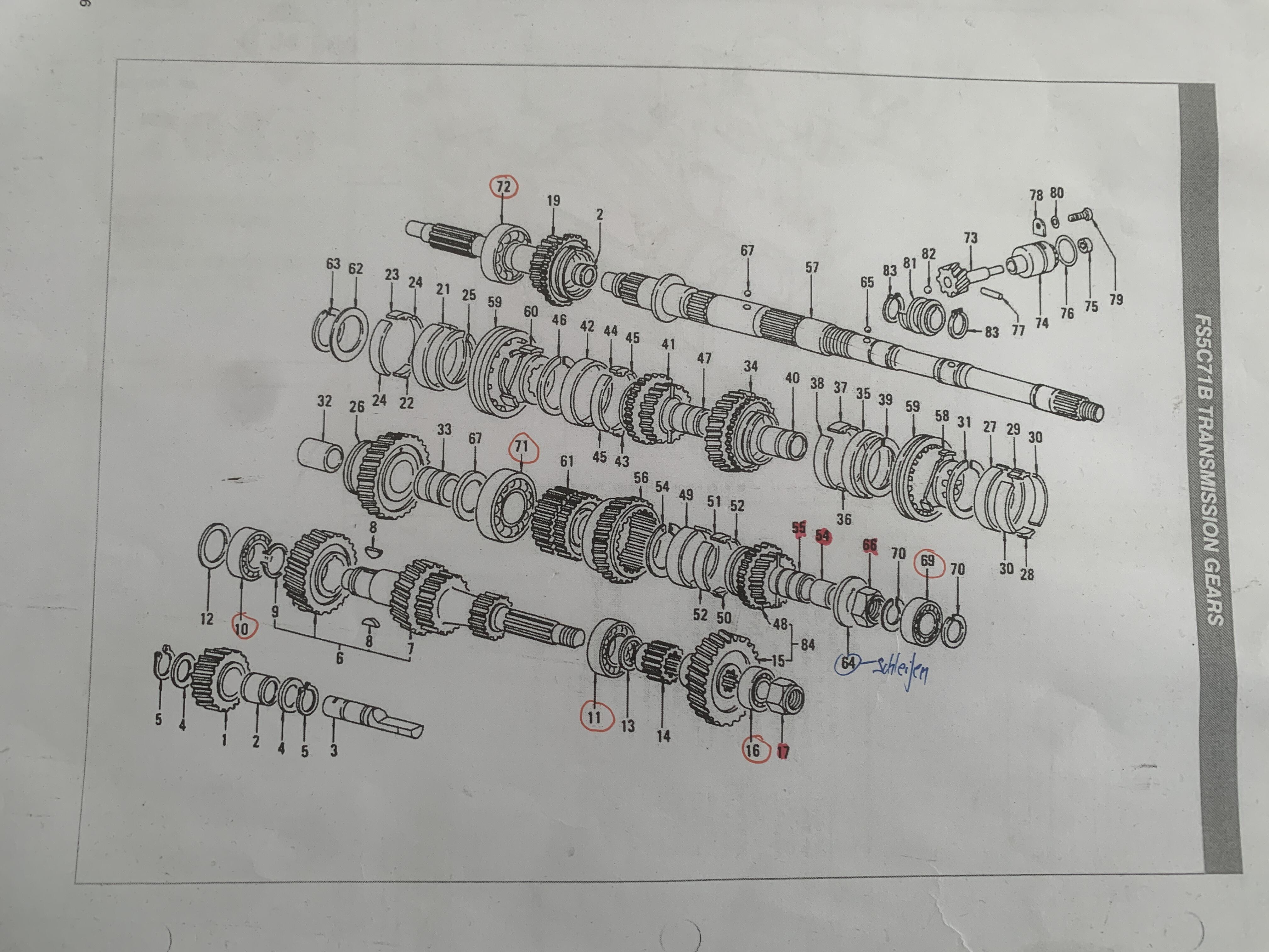
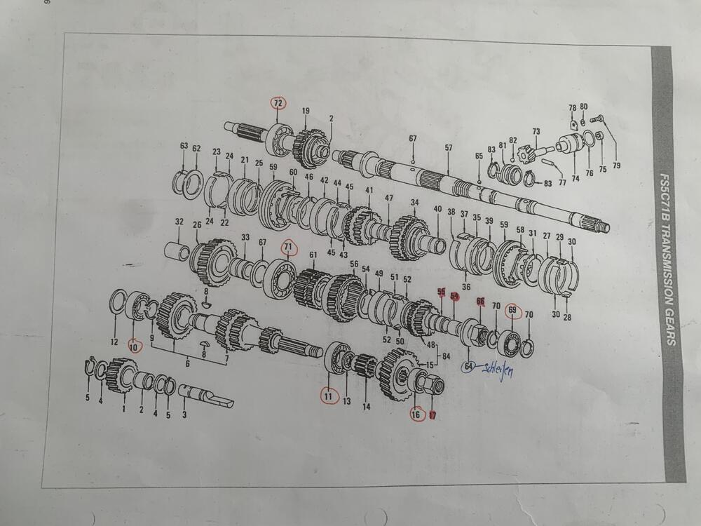
 @dutchzcarguy = yes its the porsche style syncro (FS5C71B) // I live in germany and the car is originally from italy @siteunseen = ill have a look at the springs as well but 90% there are not the issue - as all gears are super nice and stiff to shift - no wobbeling and if i shift from 5 in neutral you can feel the resistance, i think you mean this = right ? (image is not from me ) its from https://www.youtube.com/watch?v=YB_6o1De40s
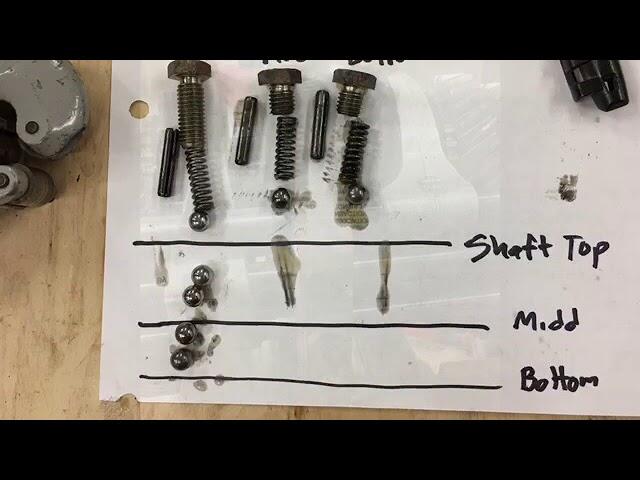
-
Found that funny.. can i get me a body in that shop!? 🤣 My tip? avoid anything that starts with "123"
-
@siteunseen He's talking about the C not the W type gearbox, a Fs5C71B is a european ( and asian??) gearbox used in the 240z with 5 speeds. THe C has Porsche steel synchro's and the W box has brass synchro's. The C box is much more rare than the W box i understand.. BTW, in what country are you @wutsin It does no longer stand in your reply.. @Mike it would be handy to have the countryname in the reply's as it ones did.. :-/
-
Hi, If you have a lot of vibrations you need to solve those but if your 5th gear pops out of gear your spring(s?) in the main plate (between the 2 halves of the gearbox) are to short and have not enough pressure anymore.. I solved this by putting in a new spring or make the old spring longer with use of a side cutter pliers! Just note on a paper the length at start and make the spring a few mm longer by cracking the spring rings with the pliers, You need to cut into the air between the springrings .. sort off.. i hope you understand what i;m saying haha, let the piers do the job, do it little by little so the spring stays straight!
-
Yes one time - and then found the issue that the nut was super loose. I tighten it but then the gap between last wascher and gear/gearbushing is too tight so it would block the gearings. We loosen the nut just a tiny bit and then we welded the nut with a tiny spot. All good so far but when i accelerate super hard from 120kmh to 180kmh the 5th jumps out by 140kmh or so. if i would accellerate slow to 180 - it would be no problem. So i thought i need to investigate a bit more and then i found a thread where someone placed somewhere there a new created 0.00xx milimeter thin brass washer. --- I assume that the no. 64 is to tight to 54 and thats the reason why there is basically no gap between 55 and 64 and therefore the gear 48 is blocked. The OLD post was around MAI 2024 still online and someone explained the same issue and postet a few pages with images and stuff he tried. ___ ill replace the transmission now with an 280zx close ratio and then ill have a look again and try to rebuild it.
-
I can inspect it in the morning
-
What is the condition of your distributor bushings? Meaning is there any wobble/back and forth movement when you move the shaft? If so you might want to go with a new system. IMO
-
-
Anyway, lots of good information not sure I have a final simple answer on which system to go with at the moment. The car is being restored pretty much bone stock except for larger intake and exhaust valves from a 280Z in the cylinder head. So. race, fancy, adjustable is probably not something that would be much of a value to me as I'm looking for a simple plug and play conversion. Much like the fireball unit I put in my 1956 GMC truck 30 plus years ago. My neighbor across the street recommended Pertronix 91761 igniter II Hitachi. Any thoughts on going that direction? Thanks guys
-
Oops, I looked for 1982 which uses the E12-92 module ( not available) and searched E12-80 on the internet. Thanks for checking. The Rockauto E12-80's look like they came from the same mold. Two choices. $42 or 126.
-
 Iirc three M5 machine screws in the armrest area...12mm length or so
 -
wheezy joined the community
-
 Matchboxes appear to be available here https://www.rockauto.com/en/catalog/nissan,1980,280zx,2.8l+l6,1209316,ignition,ignition+control+module+(icm),7172
 -
-
- Last week
-
Forgot to say that you can wire up a GM HEI module to both the Z and ZX electronic distributors.
-
I did a quick shoparound and can't find the E12-80 module, for the ZX distributors, for sale anywhere, new. Only eBay used is out there. I did run across a Mallory Unilite module for $83 on Summit. Pertronix conversions are still out there. You could use one of those to trigger an MSD6AL or a GM HEI module. The Pertronix module should last longer since it won't see the coil current. Or it might be fine as-is. The 123 looks nice in that it seems to have current limiting in the module so you can get a higher energy spark, and the advance curves are tunable. One problem with old used distributors is you get the advance curves that they came with usually, unless you can dig up other weights or vacuum advance canisters. Fun problem to have. Good luck. https://123ignition.com/product/tuneplus-6-r-v-datsun/ 123ignition is proud to announce the first fully programmable Bluetooth ignition! Control your 123\TUNE+ with your iOS/Android smartphone or tablet. The App makes it possible to adjust the ignition curve and shows an electronic dashboard. Main features: REV-counter, Antitheft system by a PIN code, Real time tuning, Vacuum advance, Boost retard, Soft REV-limiter, etc. Cylinders 6 Model Tune+ Operating voltage 4-15V Positive earth supported Yes Wires Black: coil '-' , Blue: battery negative , Red: ignition key (battery 6V / 12V) Vacuum Yes Rotation direction CW & CCW IE (D-jetronic support) No RPM range 500-10.000 RPM Brand Datsun Environmental temperature -30 – 100 °C Cap type Straight Dwell Constant current: fully automatic adaptive dwell Coil charging time-out After 1 second, coil current is turned off Spark balancing <0.5 degrees Maximum advance 40 degrees crankshaft
-
Something that is functional easy to install and gives me zero trouble for the next 20 years. I’m not too concerned about looking fancy or. correct. I just want something that’s trouble free once I’ve gone through the steps to install. It. Don’t wanna have to go backwards and fuss with it later. I’m out working on the car now. I’ll have more time to research when I get back in my office this evening. Thanks to all the input I’ve received.