


240260280z
Free Member
-
Joined
-
Last visited
Everything posted by 240260280z
-
 I guess everyone uses the timing light differently. I have an advancing light to I use a standard nulling method. At idle I just dial in advance on the light in steps until the mark on the pulley matches 0 TDC on the scale. The value on the timing light is the idle timing point. For maximum advance, I increase the throttle and watch the mark move until the mark stops then dial in advance on the light in steps until the mark on the pulley matches 0 TDC on the scale. The value on the timing light is the full advance timing point. This can be repeated at any rpm to plot the curve as well as with vacuum in and out to see its effect. When Rossiz and I tuned his Z (L28), 40 degrees BTDC total was too much advance. 36 to 38 was nicer and had more torque.
 -
Steve, I bet if you tilted the valve cover more then slanted the engine more, you could make that motor (with two parallel valve covers) look like a V12
-
Orangetange Could be caused by springs/weights/lack of lube in the distributor for the mechanical or shaft wear and wobble or spindle to distributor key wear or spark scatter caused by ambiguity on the trigger side. When I rebuilt, lubed and switched to a ZX distributor, the high end rpms smoothed and so did the observations of the timing light at full advance. You should try for 38 degrees at full you may pick up a few more HP.
-
The real thing:
-
I wonder if the glass top stove polish would work?
-
If you are attending, please email me ( philip@atlanticz.ca) with your email, hotel and cell phone at the conference. I'll put together a list and distribute via email to improve confidentiality (compared to posting this stuff on the forum). Maybe we can also organize an informal coffee, lunch, supper, drinks at a multi-purpose room at the hotel etc. First annual CZCC event?
WOW that is great 6min into the 2nd video!!!!
Also consider lack of free play in the master brake cylinder or and incorrect master or a malfunction in the master where it does not recoil.
Please email me with your phone number at the conference and where you are staying. I'll distribute to all in the list at the start of the thread. My email is philip@atlanticz.ca
I could make one with a resistor matrix and op-amps used as a comparators along with free-running ramp generator to read each array. Digital is really just quantized analogUE. I see chokes, you see core.
Another cause that I have read about is collapsing rubber brake hoses that don't let the pressure bleed off. The other causes (as mentioned above) are: 1. corroded pistons that stick 2. corroded disks that stick to the pad 3. warped disks that bind
You could also have a look up table method that plots MAP against RPM and gives the injector pulse width at that point. There would be a stack of these tables that match the engine temperature. Tweaks could be added but it should get the system roughly in the correct working area . The coil would provide the input signal for rpm counting and triggering.
Thanks for posting the door panel work and tool.... you taught me something new!
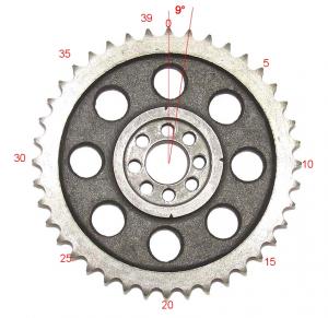
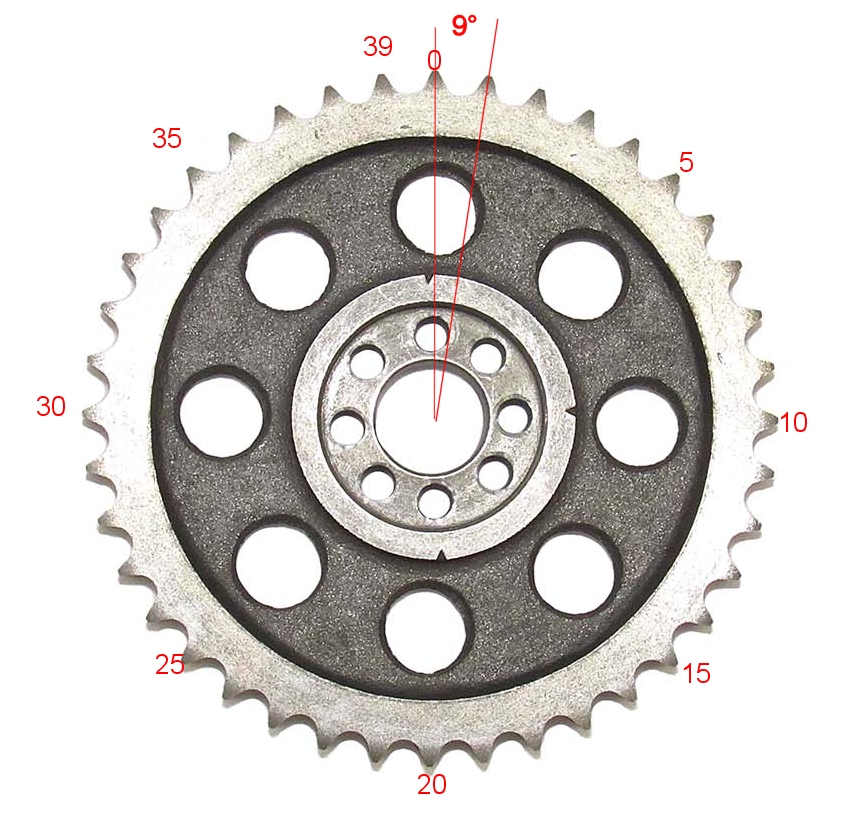
For stock 240z Cam sprockets: 0° (position 1) Cam Advance 4° (position 2) 8° (position 3) 9° (position 1 + 1 chain link) 13° (position 2 + 1 chain link) 17° (position 3 + 1 chain link) 18° (position 1 + 2 chain links) 22° (position 2 + 2 chain links) 26° (position 3 + 2 chain links) 27° (position 1 + 3 chain links) Cam Retard -1° (position 3 - 1 chain link) -5° (position 2 - 1 chain link) -9° (- 1 chain link) Note: Crank Advance is Cam Advance/2
 Congrats! Almost there.... we are all hoping for the best.
FYI: I have had bad luck with solder joints and cars. I made a copper sniffer tube for my O2 sensor that shoves in the tail pipe. The solder joints have let go many times. The combination of heat and vibrations cause the soldered joints to come apart. For your application inside the engine, I would recommend steel tube and tig welding it for peace of mind....and not pieces of engine (if the solder fails).
Nope.... it is Canada's "FOX Faux News"
http://news.nationalpost.com/news/canada/newfoundland-man-drives-18km-in-wrecked-car-cannot-remember-hitting-moose-hey-buddy-you-got-no-roof-on-your-car
Honda Insight Update: It is actually fun going slow on 3 cylinders with 12 valves. Just did a valve lsh adjust and same work as in a Z Beautiful valve train in that thang: 4 valves per cylinder off 1 cam with rollers and one intake valve is hydraulicly controlled.
It looks great Tom! I sure want to see it!
You da man!
Congrats! Almost there.... we are all hoping for the best.
FYI: I have had bad luck with solder joints and cars. I made a copper sniffer tube for my O2 sensor that shoves in the tail pipe. The solder joints have let go many times. The combination of heat and vibrations cause the soldered joints to come apart. For your application inside the engine, I would recommend steel tube and tig welding it for peace of mind....and not pieces of engine (if the solder fails).
Nope.... it is Canada's "FOX Faux News"
http://news.nationalpost.com/news/canada/newfoundland-man-drives-18km-in-wrecked-car-cannot-remember-hitting-moose-hey-buddy-you-got-no-roof-on-your-car
Honda Insight Update: It is actually fun going slow on 3 cylinders with 12 valves. Just did a valve lsh adjust and same work as in a Z Beautiful valve train in that thang: 4 valves per cylinder off 1 cam with rollers and one intake valve is hydraulicly controlled.
It looks great Tom! I sure want to see it!
You da man!

Important Information
By using this site, you agree to our Privacy Policy and Guidelines. We have placed cookies on your device to help make this website better. You can adjust your cookie settings, otherwise we'll assume you're okay to continue.