madkaw
Free Member
-
Joined
-
Last visited
Everything posted by madkaw
-
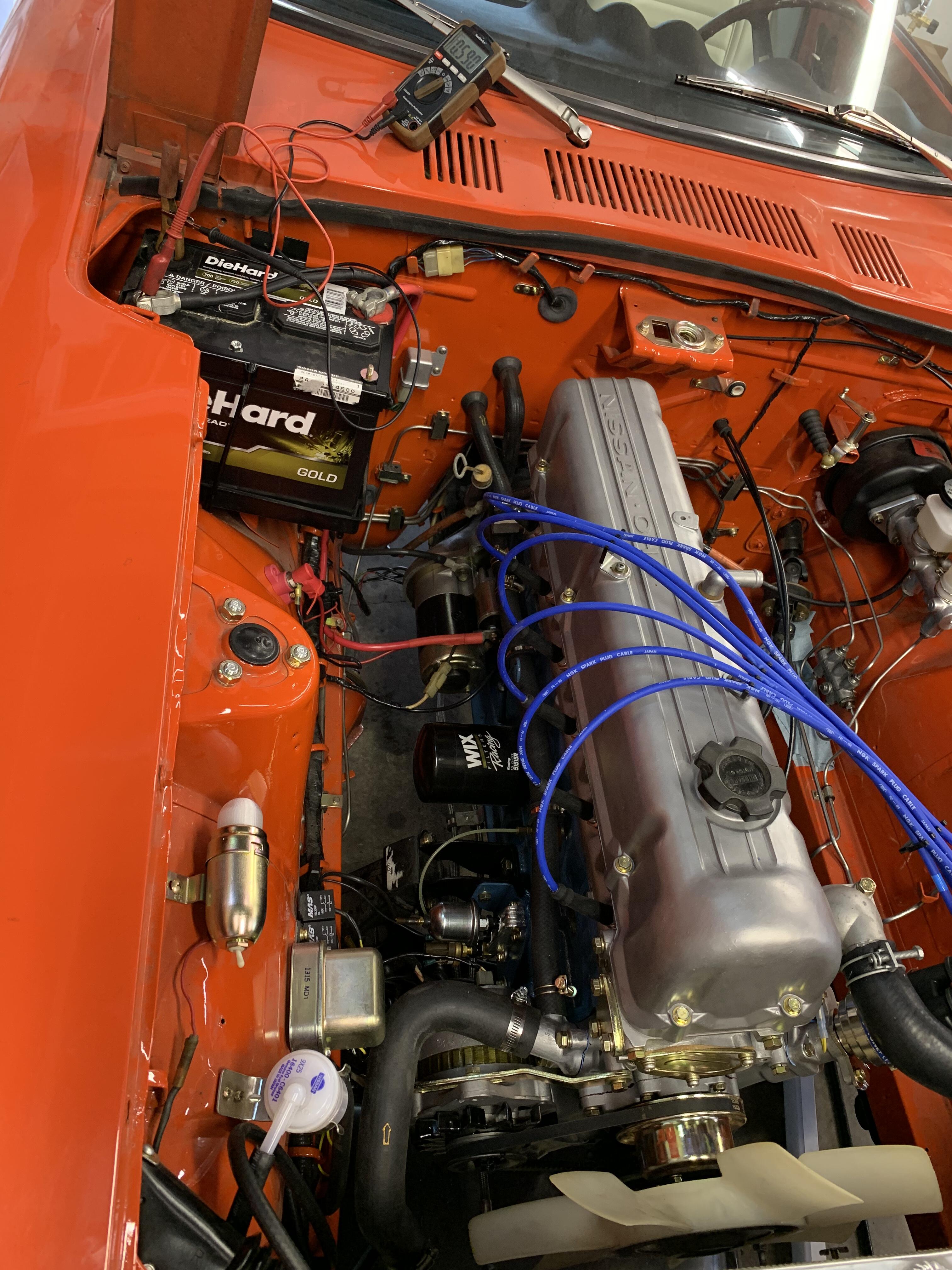
 Hey guys , I guess I’ve been away from carbs too long and now I can’t work on them . A customers car that hasn’t really run yet since rebuild . Trying to set my float levels and using a float sync tool to help assist . The problem I’m having is that I have one carb that wants to be ole faithful . Even if I adjust it for a low fuel level it will eventually overfill. I am using a Holley Black fuel pump that is rated for 4-7 psi . I also installed a Mr Gasket inline fuel pressure regulator set at 2psi . I had an extra needle and seat laying around and swapped it out , no difference . The carbs were lightly rebuilt with new needle and seats from Z Therapy . Not sure what to try next. The front carb seems to be doing fine and holding a certain level. I was considering swapping parts from front to back and see if the problem follows . Any thoughts ?
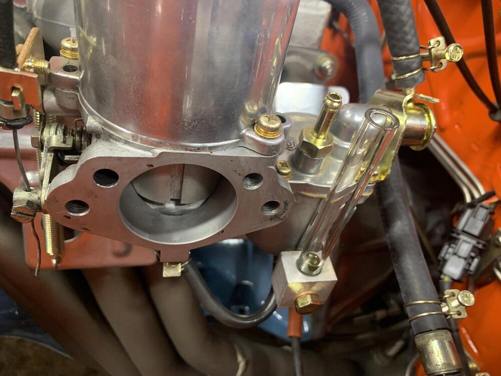
-
Bizarre for sure . Laser temp gun to verify readings . Not sure what to suggest other than replacing the sender sensor to start
-
They won’t take calls - which sucks . They are usually good with replying to emails
-
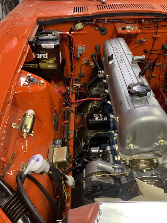
Nice set up. The n42 pair is not my favorite for modification . I would definitely want flat tops for the block - but that’s all the mods needed there . The head is going to be a lot more work . The best solution to keep down time to a minimum is to have another head rebuilt and ready to go . I would source a higher quench head - p90, p79, mn47 . They will do better with pump gas . Or maybe just find a zx motor and use the block and head . As far as the cam - going big or go home .
-
All those heads should be drilled for carbs . N42 is your best bet for dished pistons .
-
View Advert 1970 fuel tank I had this extra tank that I decided to move along . I painted and sealed the inside of the tank . You can see by the pics that it was very clean inside even before I started . I used Por-15 tank sealer per their instructions. For some reason I had some bubbles pop up on the bottom of the tank . I contacted the reps for Por-15 and they acknowledged that this happens some time , but no worries on the integrity of the sealer . I painted the tank outside with SEM trim paint . It has newer Nissan sender and new drain plug . Asking 300$ Shipping will be thru FedEx and I will only charge actual shipping cost . Advertiser madkaw Date 06/22/2022 Price $300 Category Parts for Sale
-
Stock r180 with a Rebello power and one weak point and bang . I’m with everyone here about checking diff . Try the Subi diff swap - it makes for a tougher r180
-
Well back to the shop with it
-
The drain stops when I pull the T plug . I can make the regulator click by removing and installing the T plug .
-
I thought about ditching this older style with an internally regulated style - but his electrical needs were so low . what’s the chance of having two bad regulators - that’s what’s weird . I don’t have a FSM . Maybe see if my Hanes has any info .
-
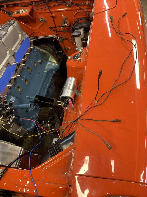
I have a .5A draw. Pulled all fuses one at a time Alternator and starter have been professionally rebuilt . Replaced voltage regulator which I thought was the issue . It clicks when connecting the battery cable . Old one and the new one . It also gets warm . 2 bad regulators ? When I pull the field plug it quits So my white 12v from the starter is intact . I have 12v at the plug for the regulator ( solid white ) I have continuity from the WB at the regulator to the WB at the field plug . That makes me think the regulator is not supplying the 12v at the plug .

-
And it’s not the only Jeep part on my car - lol
-
I do have a Datsun soul . It does work well and glad to see people using it
-
Well I have answers and have to fess up of a mistake . The yoke sent to me was only 24 splines but skips teeth at 180 degrees . They call that a 26 spline I guess . I didn’t at the time check the actual measurement of the yoke and ASSumed it wouldn’t be right , but it is . So the 83 turbo - regardless of manual or automatic have a larger output shaft with 26 splines . I had no clue .
-
Thanks again . I know the block is a great ground , so I am over thinking things . I’ve cleaned all the grounds everywhere on the chassis .
-
I’m building a little 1972 resto mod for someone. He wants to keep it automatic . I did some searching and realized the 83 turbo automatics had a lock up torque converter - badly needed really . I acquired one and on install DS from the 72 wouldn’t fit ( 24 spline -24mm) . The 83 zxt( at least this one) has a 26 spline output -26mm OD. I sold my last t5 DS and it had the oddball yoke - I believe is 26 spline . I’ve talked to many people that automatics and no one has one with a 24 spline output . Ordered a new yoke from Z Car Depot that they said had 26 spline . Came today and it was 24 spline 😡 I know autos are spoken about much , but maybe someone knows something
-
Awesome @SteveJ explanation . More stuff to delete ! The diagram you picked is correct for my 123. The blue wire is about two feet long . I was hoping one of these wires I don’t need anymore was a good chassis ground . I’d like to get as close to the battery as possible . I figure a good ground is essential . Too bad my harness is all taped up and pretty . I just didn’t want to take anything out that broke the circuit of the inhibitor or somehow alter the operation on the automatic .
-
There’s a thermal relay that the RB wires runs thru . There’s also a thermal switch in there somewhere . Not sure what their function is . So you think I don’t need to connect the RB to the coil - like in the original wiring ?
-
I thought the fit was quite snug - but I’ll look at it again
-
Hey guys , I’m installing the 123 ignition on a customers car and he has automatic transmission . This is a 2/72 . I’ve been looking at schematics and I’m trying to educate myself on inhibitor switch’s and the rest of the workings of the auto trans . I don’t have a FSM and I’m using a Haynes manual and it doesn’t cover the electrical side of the auto trans . I just ordered a FSM for the chassis on S-30 and hope that help. My current concern is Red/black wire that splits to the two blacks - going to coil - and distributor . I would think that these are part of the inhibitor circuit so I need to tie these into the circuit with the 123 ? Are these grounds once all the requirements are met in the inhibitor circuit ? Trying to figure what the thermo relay does ? Every black wire I measure shows no ground . Makes me wonder if that’s an issue. One last issue . It seems I have a battery drain . When I hook up my battery cables the voltage regulator clicks like a relay - is that normal . After charging my battery i checked voltage and lost .5 volt pretty quickly . The voltage regulator was warm
-
-
View Advert (M)N47 cylinder head I will have this MN47 head available in the next month for purchase . I am advertising now in case buyer will want modifications to intake opening( gasket matching will increase cost) . I do not want to be sanding on this after I have assembled . I can take port opening out to 38mm to gasket match buyers induction . The head will come ready to bolt on . Clean with valves adjusted to proper spec and clocked properly for assembly. This head will fit any L6 . This is the same head I use on my 3.2 . Any modifications to ports are modeled after my engine ( 230 rwhp 35mm port and stock n42 intake) This heads makes for excellent street performance. Please PM me for additional info . You can also email me sfinnerty1018@gmail.com 1984 N47 from Maxima ( fuel injected ) Head surfaced 3 sides - MLS compatible. Head vapor honed All threads chased 39cc closed chamber 35/44 Datsun Spirit valves New valve seats blended to ports Complete valve job 35mm intake port opening Ports and bowls worked ISKY springs & retainers Resurfaced Nissan rockers Steve Bonk cam (535 lift) Here’s a description of the L heads from a prominent builder that posted on Hybridz: Here is my personal take on the L-series heads. E-31 and the early E-88 heads with the E-31 chambers are decent heads. They have the same potential as the other N-series heads when rules permit extensive carving. My opinion is the best place for the E-31 and the early E-88 is for a restoration project, or for a performance application where class rules dictate no material can be added to the chambers, no carving can be performed on the head and the update/backdate rules apply to the engine as an assembly, then these heads are a great choice. Now if you are not bound by those kinds of rules, you do have other choices available and being as the E-31 is becoming so rare now, these other heads are an easier option from a financial and availability stand point. The N-42 head is a great maximum effort race head if class rules allow extensive carving and welding to the head. In this case, weld the chambers, open the exhaust ports as described above, perform some serious valve unshrouding and “waa laaâ€, you now have a wonderful maximum effort race head that would SUCK on a street engine. (Side note; If you intend on having your valves unshrouded and have not done this type of work before, you are best served leaving this to a qualified experienced engine builder, preferably one that has been successful in extracting noticeable to impressive documented performance gains. If you are not sure what you are doing, do not attempt to unshroud the valves yourself. In experience can hinder the flow worse than what the heads were stock.) Of course there is more to building/machining/porting a maximum effort cylinder heading than just welding a chamber and/or unshrouding valves. There are items such as setting spring heights, clearancing the retainers, stem seals, and guides for the mega lift cam, deciding on just how far to go with oversize valves even to the extreme of offsetting the valve guides to allow even BIGGER valves if the cylinder bore permits, etc. The Z car N-47 head is a great street head. This head becomes almost ideal for the mild to hot street engine and even the mild to moderate race engine especially if the chambers can be welded up, (pretty much turns this head into the Maxima N-47 head which is a slightly more efficient chamber than the E-31). This “peanut†or “kidney†shaped chamber when used with flat top pistons or matching* dished pistons gives the ideal quench area which makes for a more efficient combustion process. To make use of this “kidney†shaped chamber on an L-28 running pump gas you will need matching* pistons. What I mean by “matching* pistonsâ€, is a set of custom pistons from JE or other comparable source that has CnC the dish directly under the open portion of the “kidney†shaped chamber, not the entire surface area of the piston as is the OE 1975-1980 L-28 and all L-28-ET pistons. Any how, with this ideal squish, the engines optimum ignition advance will be less than the open chamber heads optimum ignition advance due to the more efficient chamber design. This happens because the flame front doesn’t have as far to travel to consume the entire air fuel mixture within cylinder, it now is in smaller area so the flame front doesn’t have to travel all the way to the other side of the cylinder during the ignition sequence. To better understand this concept, just visualize the open combustion chamber as being a flat wide circular disc, the diameter of the cylinder itself containing the air fuel mixture with the spark plug on one side, vs a small kidney shaped ball containing the same volume of air and fuel. Ideally a sphere shaped chamber with the spark plug in the dead center would be perfect, since that isn’t realistic, tuners just try and get as close to this ideal as possible. Some engines came for the factory much closer to this ideal, ala HEMI heads, etc. As for those round exhaust liners in the N-47 and P-79 heads, they actually flow VERY well. The liners offer a nice gentle radius as the air flow transitions from a vertical flow out of the chamber to the horizontal plane where it meets the header which keeps the air flow moving undisturbed even at high velocities where as the square ports with their really sharp short side radius doesn’t allow the air to make that transition with as much ease. What happens is the boundary layer of air along the port floor can and will separate causing the air to slam into the roof of the port and tumble along the floor of the port when the velocity gets high enough. This is not a good thing in the quest for power as this turbulence is very disruptive to air flow. This why we make that region of the port, the bowl, larger in an effort slow down the air flow to keep that laminar air flow across the port floor. Of course this only happens at very high velocities. Also, all L-series heads starting in 1977 have a slightly smaller intake port volume. What the engineers did was cast one side of the intake port wall with a “flat†in it, “D†shaped if you will. This reduction in cross sectional area starts approx ¾ of an inch into the port. This port shape is supposed to help bias the air flow as it enters the chamber more towards the middle of the combustion chamber itself, steering away from the chamber walls is passes the valve head. In theory this helps to reduce some of the air from slamming into the chamber walls of the combustion chamber. I don’t have enough hard evidence to back up this theory, but I do feel that this port bias does not detract from the performance potential of the cylinder head one bit. Now we get to the P-79 and P-90 heads. The combustion chambers of these heads are IDEAL, almost perfect once the valves are unshrouded. The only down side I see to the P-series heads, (and this down side is for the extremely radical ragged edge engines, not so much for the milder even hot race engines), is since the chambers are taller, (valves are now shorter as a result), the floors of both the intake and exhaust ports now have an even sharper short side radius and as stated previously, this is a detriment to flow as velocity increases. The transition from the horizontal plane to the vertical plane on the intake and vice versa for the exhaust, is not as smooth as the N-series and E-series heads. Now don’t take this as I am bad mouthing the P-series heads cause I’m not. I really like these heads for hot street and mild to moderate race applications. They are an inexpensive way to get the ideal squish using an OE flat top piston with a compression ratio compatible with pump gas. I have built several and will continue to build the P-90 and P-79 heads for street and mild race Z’s. What I’m saying in regards to the P-series from the stand point of building THE mega extreme N/A performance power house that is at the ragged edge of making useable power over a very narrow yet very high RPM range such as a best of the best N/A drag racing engine, these items should not be overlooked. Maxima N-47 head. What a darling mild race head this is. For mild to moderate race engines on a budget, using flat top pistons in an L-28, or even opting for pistons with a slight dome for greater than 13:1 compression, this is my go-to head. Just have your machine shop cut out the old intake seats and install the larger seats for the 1.73†or larger valves, have a competent Datsun engine builder/tuner unshroud the valves, blend the exhaust seat into the liner, and “waa laaâ€, a moderately high compression ratio race engine that will perform rather well up to 8000 RPM with the right cam, induction, and exhaust system. With a set of custom pistons machined so that the dish is directly under the open portion of that gorgeous peanut chamber, this head, in my opinion, makes for the perfect street head or mild race engine that runs pump gas. At the moderate level of race and above, I tend to prefer the N-42 with welded chambers and opened up exhaust ports. Now for that flow bench info I promised earlier on… Since a flow bench cannot duplicate the dynamics that are happening within the intake and exhaust tracts while the engine is actually running, i.e. sound pressure waves, pressure surges, exhaust heat, fuel enriched intake charge, valve overlap extraction, etc, flow bench numbers are nothing that should be used for comparing one head to another or bragging how good one thinks their head is! The best way to use flow bench numbers is using the SAME flow bench to compare ONE cylinder head for improvement after modifications have been performed, making note of any changes in air flow whether improvements were made or lost, nothing more. Flow benches do not represent what is actually going on within the intake tract OR the exhaust tract as mention previously, i.e. Dynamic air movement, pulses, waves, heat, etc!!!!. In real life, the valves are opening and closing causing the air to stop and move, stop and move, over and over and being as air has weight and is compressible, this constant surging will cause the pressures to rise and fall FAR above and below ambient. Depending on RPM, runner length, runner cross section, port shape, number of bends in the port and radius of those bends, valve shrouding, air density, cam timing in relation to the piston movement, (this has a HUGE effect on how the air gets moving within the intake and exhaust tracts, hence lopey idles, hard hitting powerbands, etc), there could be higher than ambient pressures at a particular RPM, i.e. a natural supercharging effect, that is why intake and exhaust runner lengths are TUNED! We have all seen where almost all Nascar engine builders have achieved over 110% volumetric efficiency on a naturally aspirated 2 valve engine by tuning the intake AND exhaust tracts to a specific RPM with specific runner cross section and runner lengths. This tuning is taking full advantage of the Helmholtz principle. Your basic garden variety flow benches do NOT and can NOT duplicate this, I’m not even sure if there is a flow bench made that can do this. The only real measure of how good a port can make HP, is to mount that head on an engine and run that engine on a Dyno, (and this is what we are REALLY after right, HP! Not just some arbitrary static flow number through a head port)! An example would be if one head that on one flow bench indicates it will outflow all the others tested, when all are attached to equivalent short blocks, the high flowing head could easily make LESS power on the dyno, but then again change the configuration a little with a different cam, intake tract, piston some shape, etc, the results would get even more confusing. Advertiser madkaw Date 02/17/2022 Price $2,600 Category Parts for Sale
-
Wow - serious shine !
-
That was a fun engine - but the 3.2 is almost brutal . Need to try and duplicate that chirp with the stroker
-
I’ve been retired since 2018 actually . I’m very lucky to get to play like this . Hope my body keeps up with my mind