HusseinHolland
Community Member
-
Joined
-
Last visited
Everything posted by HusseinHolland
-
Been going around in circles (feels like endlessly) with the garage wiring. Initially, I just wanted to replace the existing old wiring with new, keeping the basic circuit as it was, then adding new circuits for the outlets and lighting I want to expand with. However, it's going to be better to run all the circuits now, so I know the conduit will fit where it needs to go, even if I don't have the new mains supply in place. My normal car-related method of some planning & some winging it really isn't going to work with the garage. I need to write this all down, as it's just going round & round in my head. 1) I can't find online what the code is for placement of the underground rated 6/3 UF-B I bought (to allow for 240v outlets), in terms of termination at the supply (house) and at the garage. From what I can ascertain, where the wire enters the structure, it needs to be joined in a junction box (code for specific height off the ground?, don't know), rather than feed continuously through the structure wall. I'm going with 2' burial depth based on online info, then where it needs to come up & enter the basement and garage, I can fit it in 1 1/4" PVC sched 40 conduit. Can't be smaller as the 6/3 cable is too rigid to roll or squeeze to reduce width. I don't think conduit is required by code, however it will be where the cable comes above ground, so it seems to make more sense just to have conduit from start to finish. reference for appropriate receptacle wiring YT video - they don't use conduit in the "raceway" (?) - they poured concrete though. I think I'll just get conduit. Edit found this regarding connections at either end (link😞 So, I could just run the 6/3 all the way to the main panel, where I will have a mains breaker to disconnect the entire garage. Or, if joining outside, use split lugs in the appropriate 6AWG would seem to be OK for this junction, either sealed versions or wrapped. It looks like I need 2 x 8' grounding rods at the garage. can't figure out if there is a code for how the grounding cable is supposed to exit the garage & attach to the closer rod. 2) For inside, I bought NM-B wiring; 10/3 for (30a) 240v outlets, 12/2 for (20a) 120v outlets, 14/2 for lighting circuits, 14/3 for the one 3 way circuit that governs all the existing lighting. I'm using online guides for load rating. As far as I can determine online, NM-B does not need to be in conduit placed over 7'6" - up in the rafters & top plates, basically, which was one reson for buying it. However, since this is the garage & not a basement, I want to make sure all the wiring is protected from potential harm, and I can't figure out if there is a local code requirement at play - that info is not made public, I don't know why - besides the fact that they only want electricians doing all the new wiring. In any event, I really want to make sure I'm meeting potential code requirements, even though I don't know what they are I started running 1/2" PVC sched. 40 conduit to replace the old (MC?) cable, routing it along the existing path, but adding some junctions to allow for some flexibility. Separating the new outlets & light into a new circuit. For the south wall receptacles, I am running 3/4" PVC conduit (to make sure there is not a fill issue) for the 10/3 and 12/2 combined - from the north wall, over the west wall, to the south wall. I'm going to have the outlets approx 4' off the floor, in conduit going to exposed boxes. The single 240V receptacles will be in a 4" square box adjacent to the 4" double duplex 120v receptacles, that way I don't have 2 separate conduit runs along the middle of the south wall, and over the west wall coming from the mains panel on the north wall. New lines replacing the original single circuit switched lighting and (3) duplex outlet boxes. Loose MC cable for attic lights will join the junction box shown. May have made sense to use 3/4" conduit & reduce the number of runs. Shouldn't matter here, as I'm not going to run any additional wiring on the center beam. I don't want to run any wiring over the north wall at this time, as that is where I want to make the 14' bump out. Need 120v outlet and 3 way lighting switch at the garage door (old layout) and I want a (30a) 240v receptacle below it - 10/3 will be added in a conduit & pass though to lower 4" box. I have exposed work 4" metal covers to house the switch & receptacles 14/3 for the 3 way, 14/2 is for the 15a outlet just used for lead lights & battery chargers (edit - probably going to pull the 14/2 & replace with 12/2 so I can use the 20a outlet here) More to follow
-
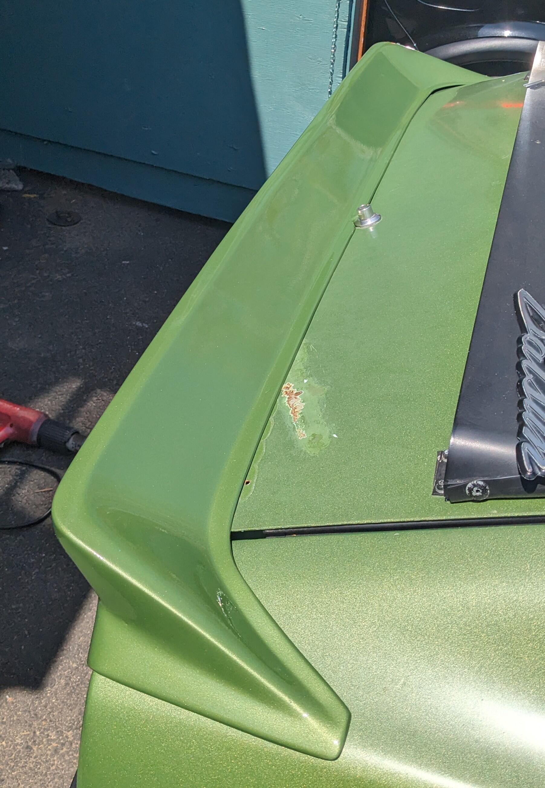
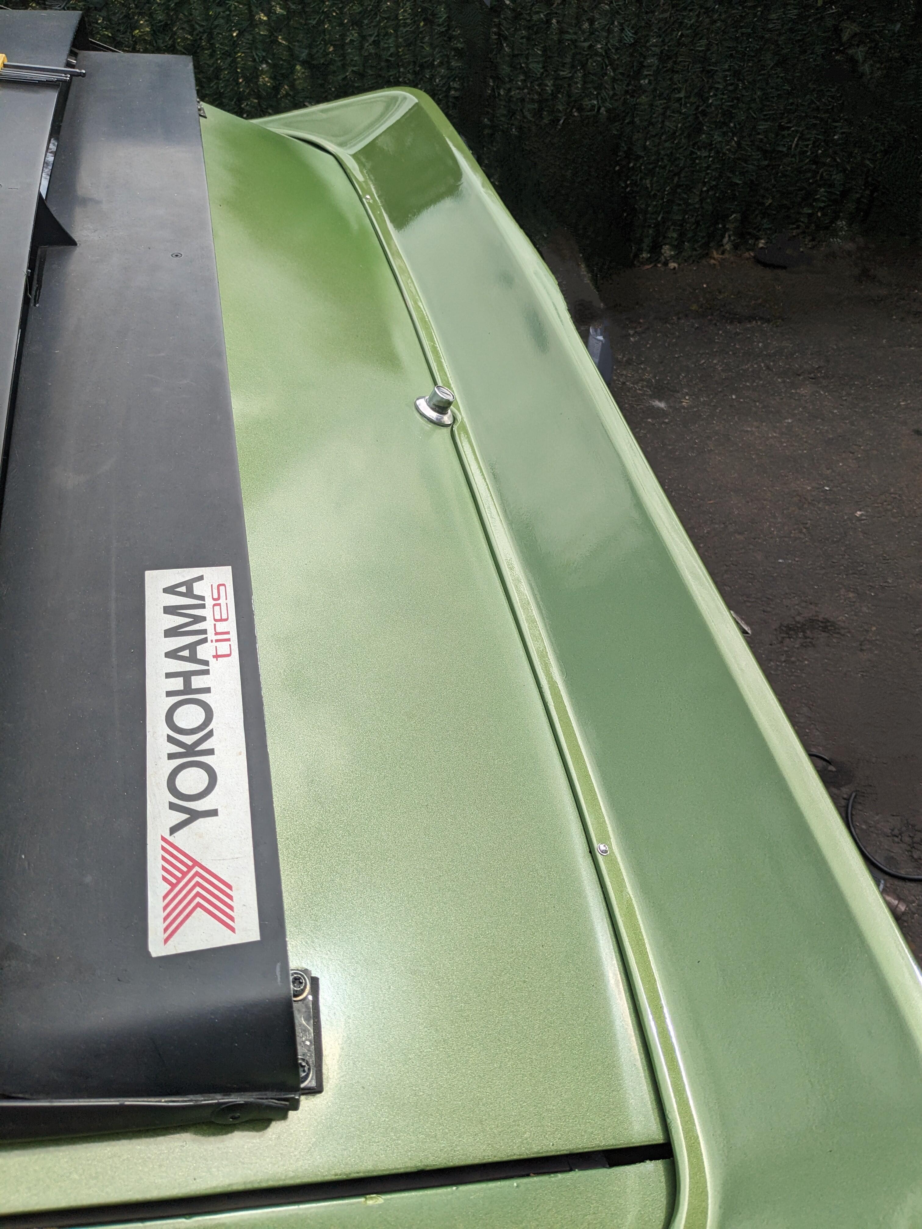
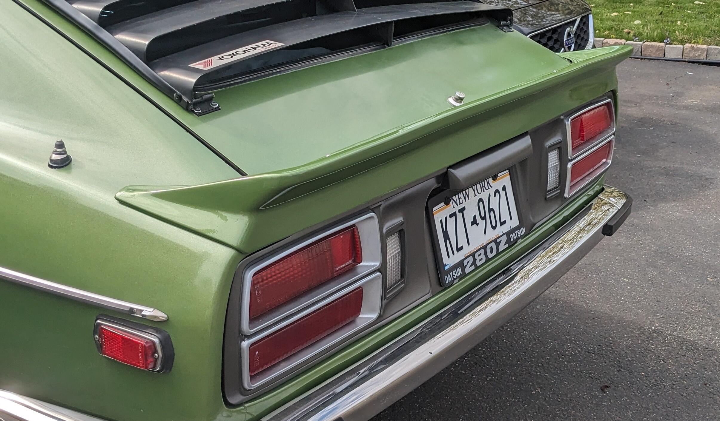
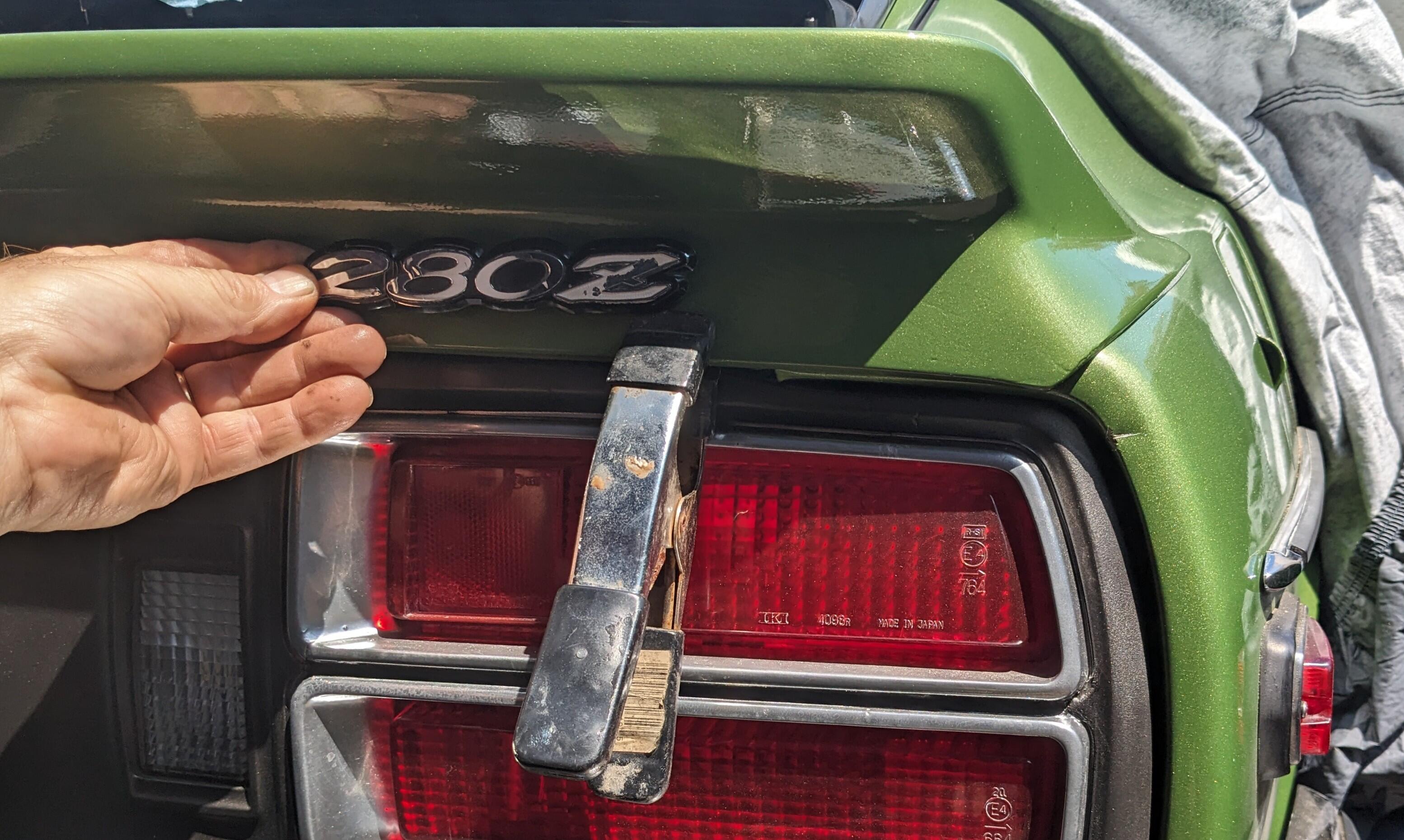
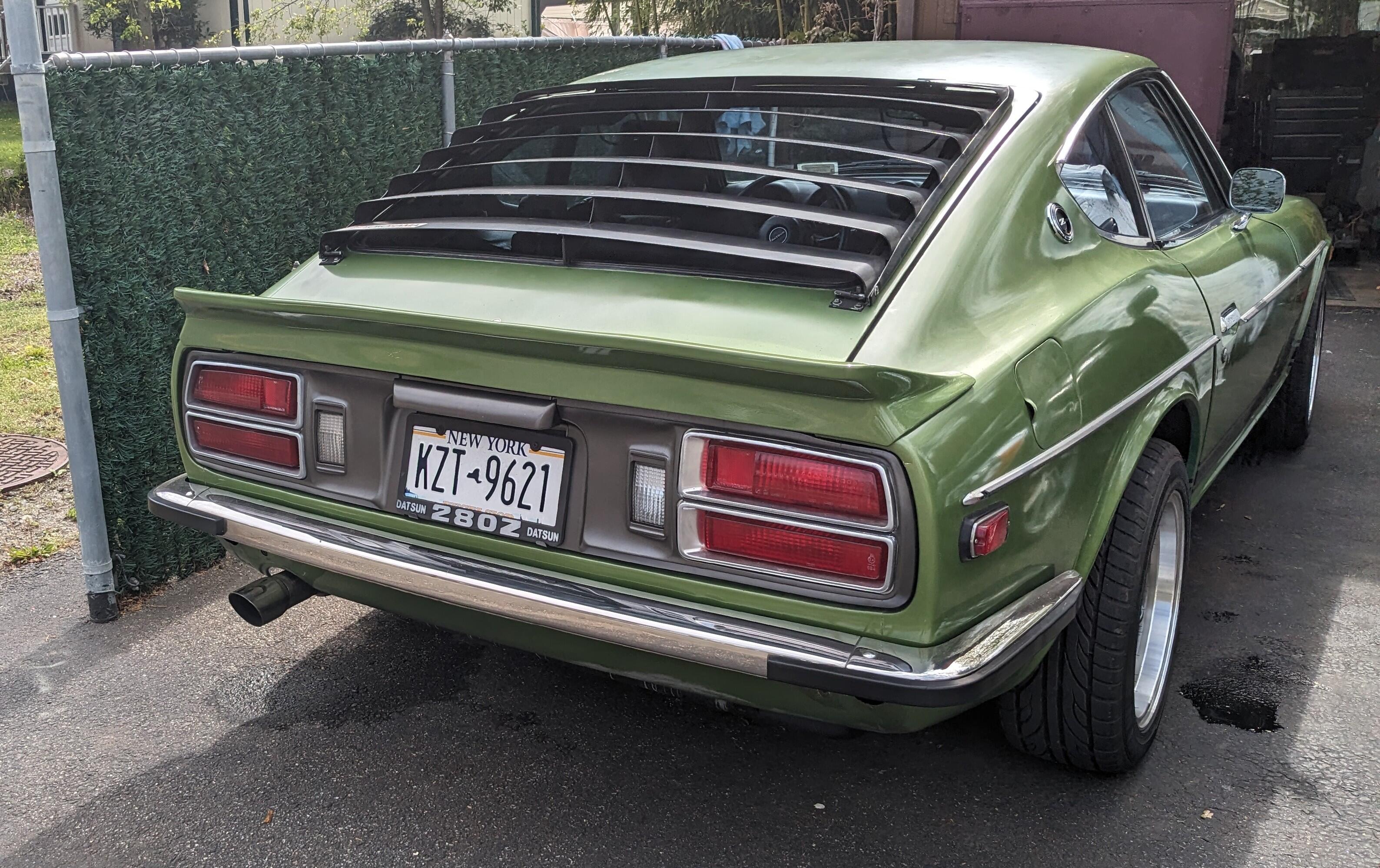
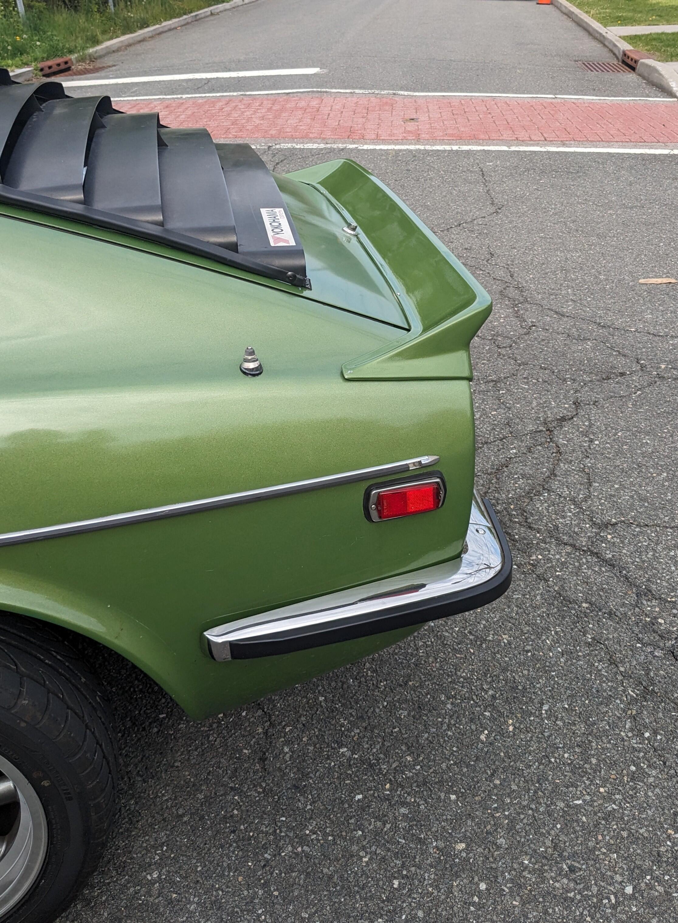
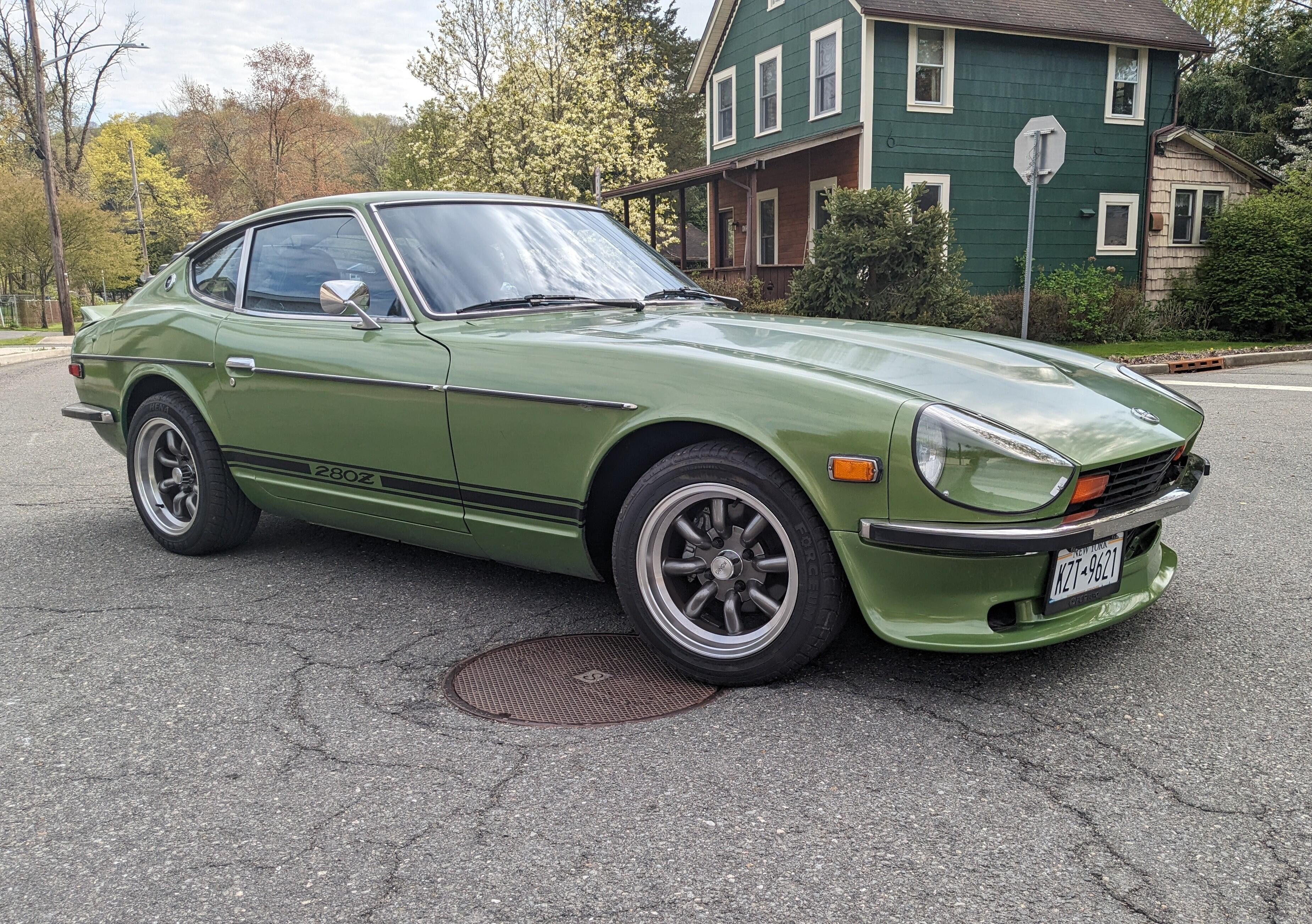
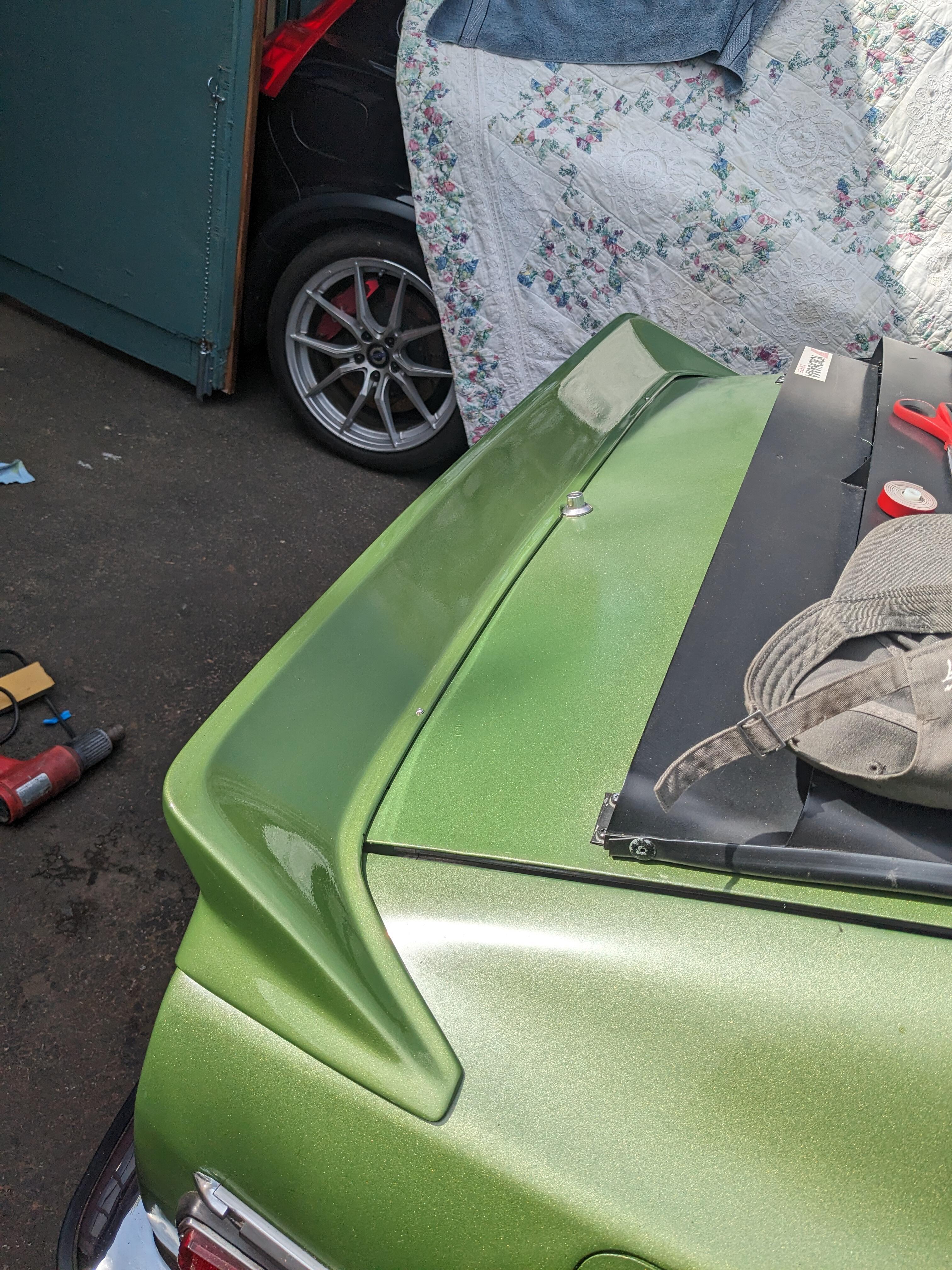
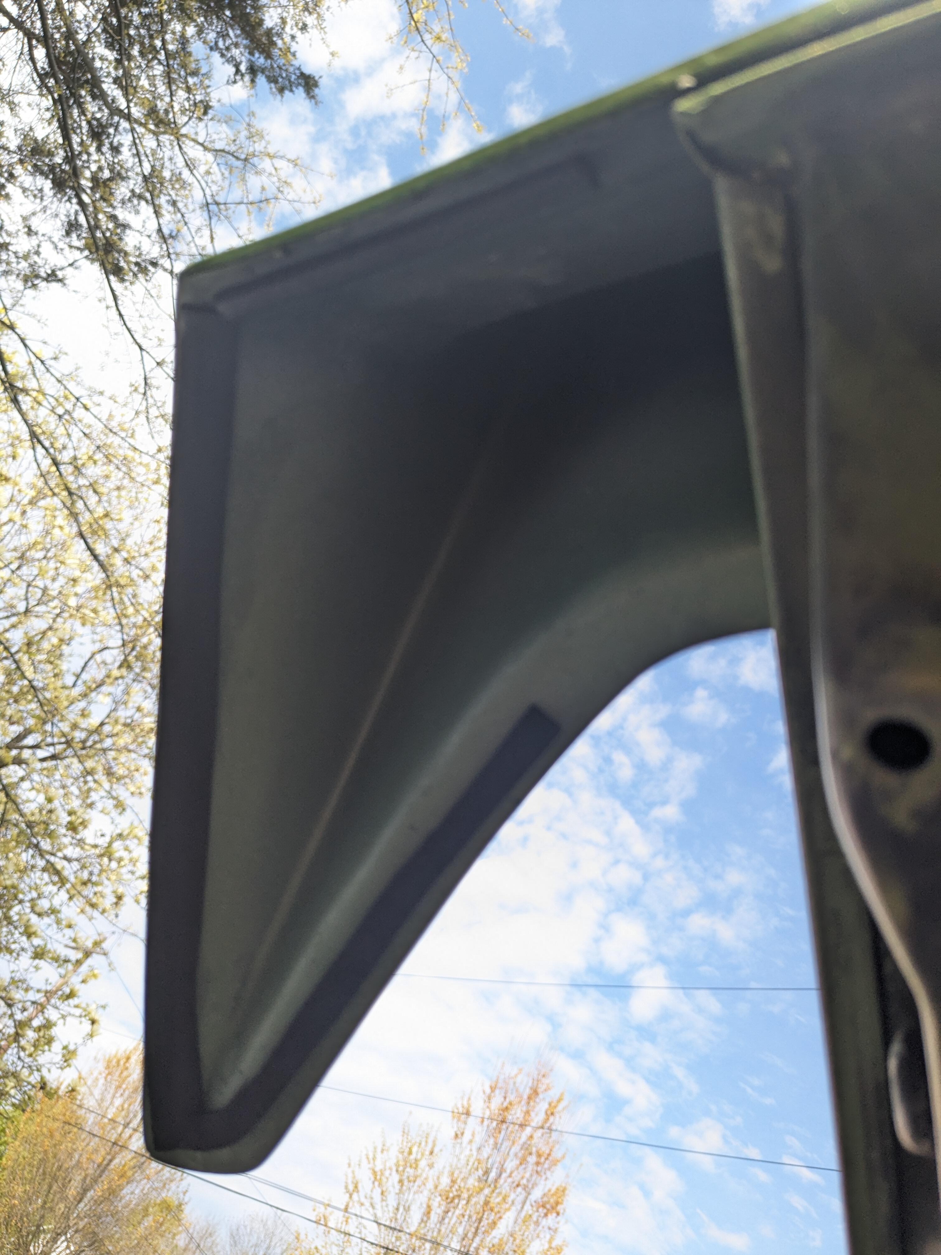
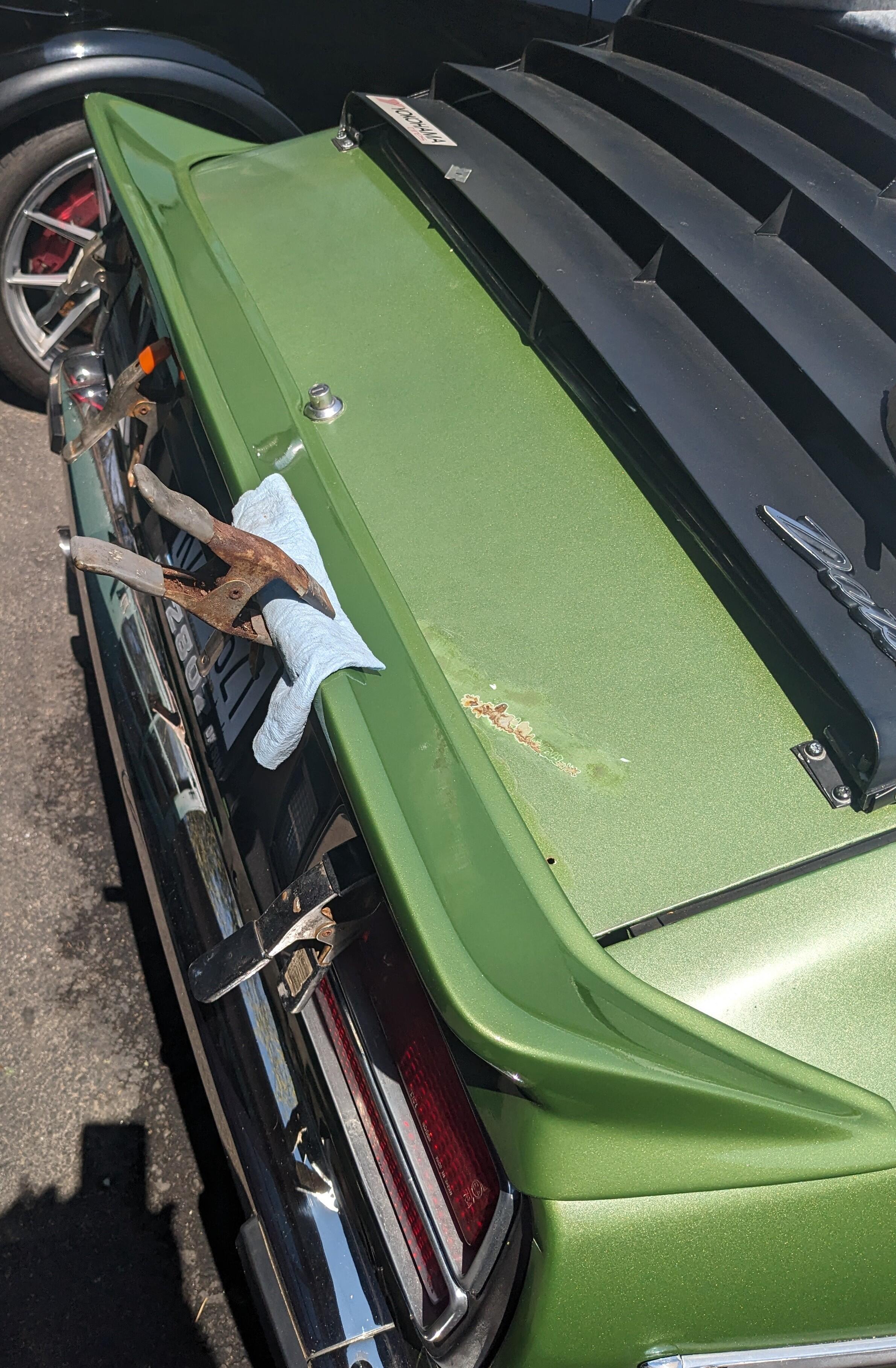
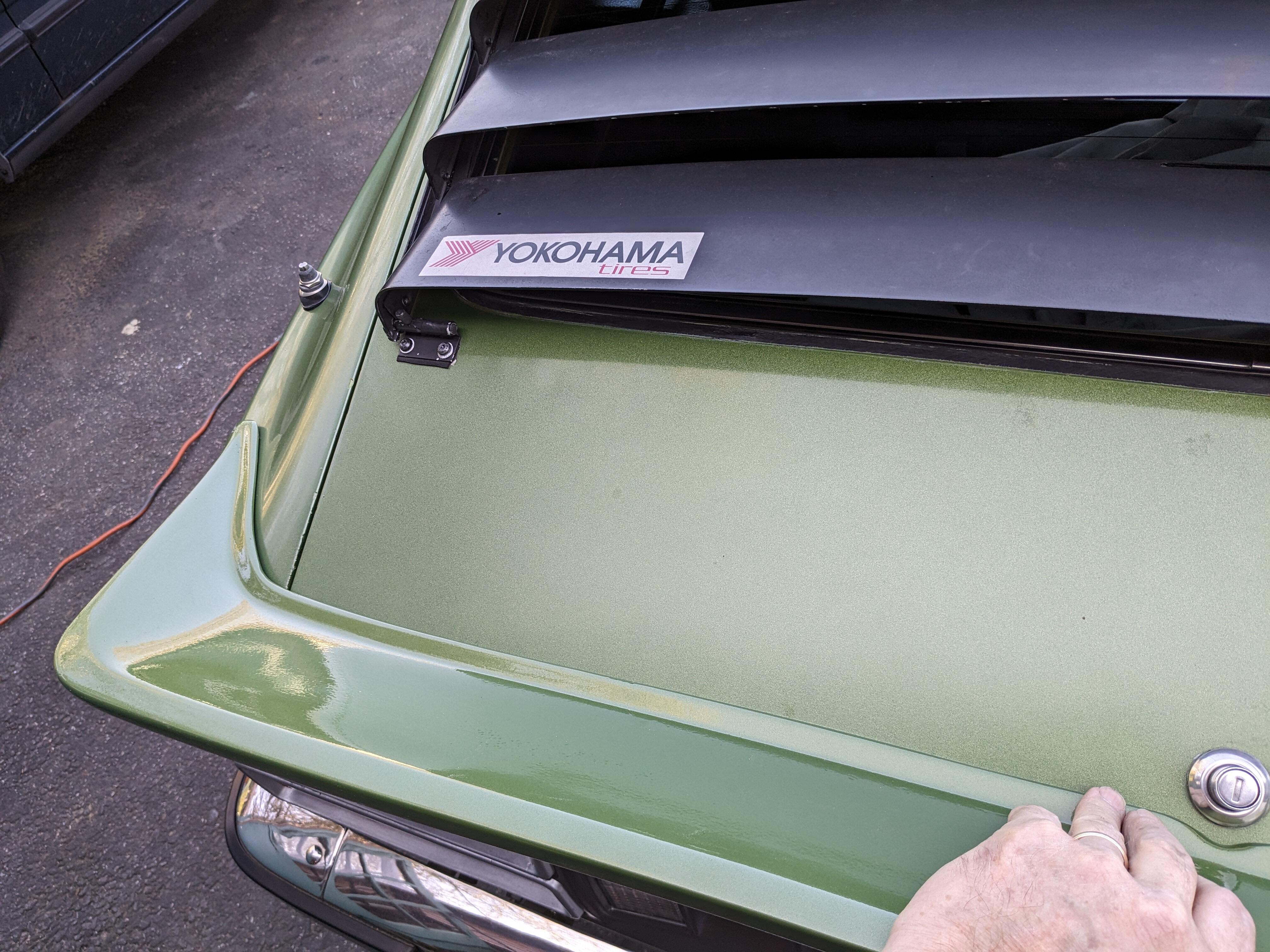
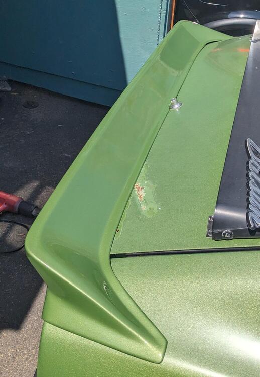
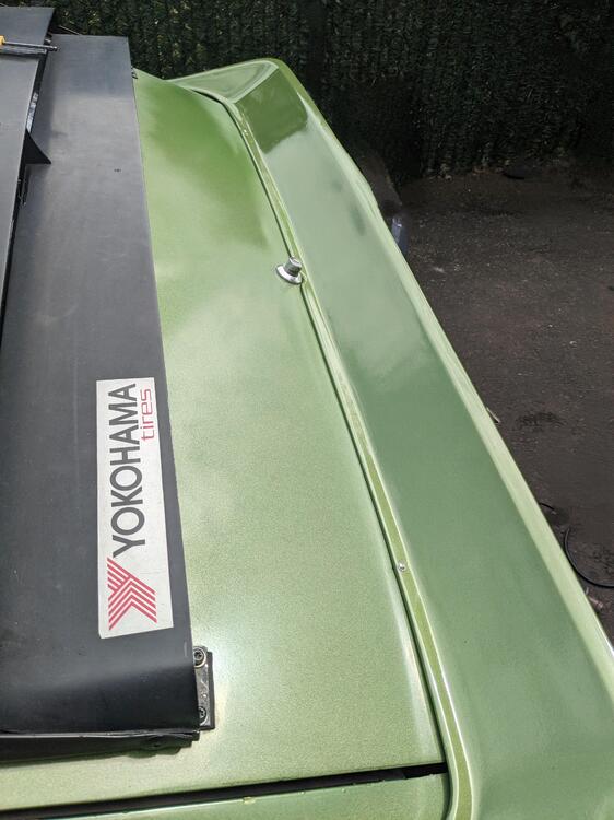
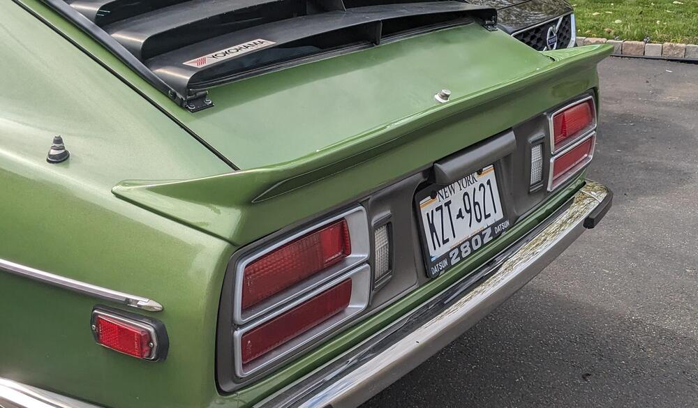
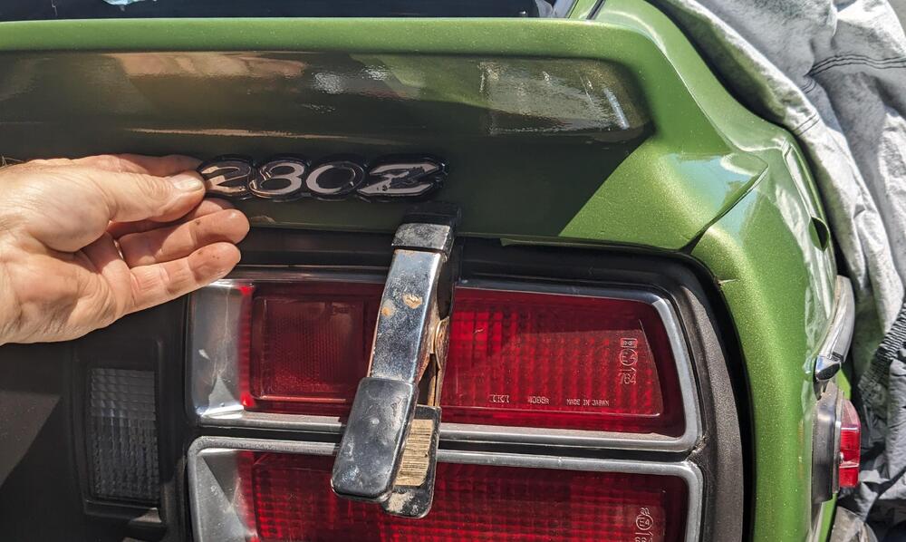
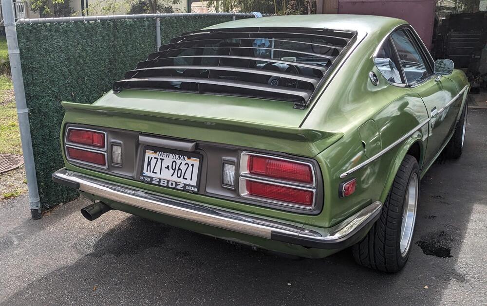
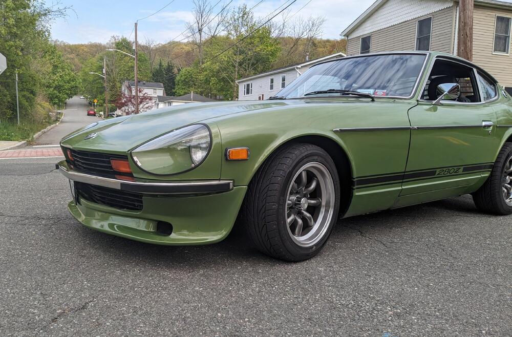
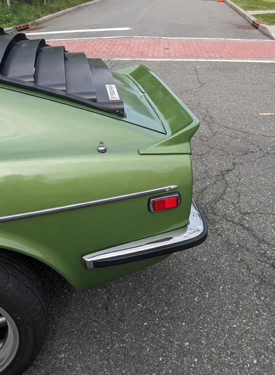
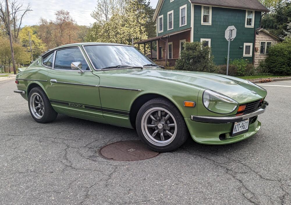
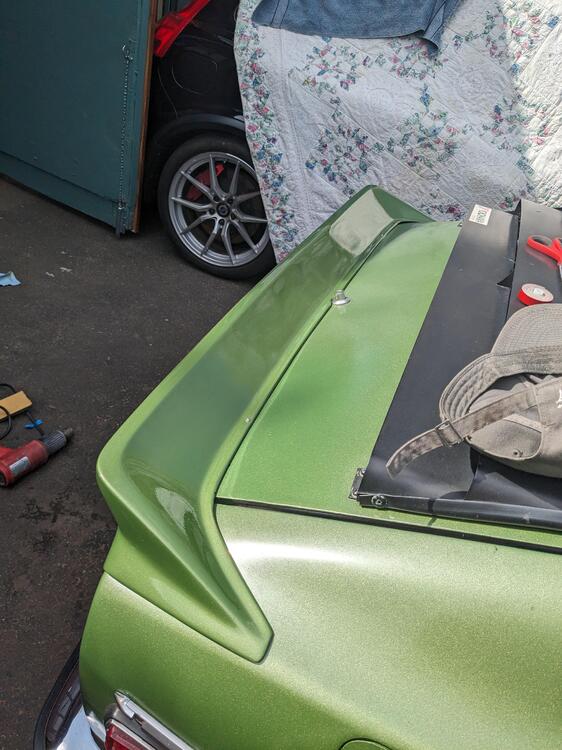
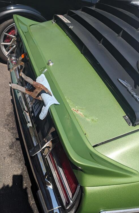
Plenty of sun today, so I clamped the rear spoiler to the hatch along the back edge & let it bake awhile. That actually resolved much of the misshapen issues, added a clamp on top which pushed the wave that was present on the right out. Had to address the paint under the emblem also After paint repair The directions say to drill & use two sheet metal screws in the forward outer region, after the spoiler is taped in olace. I used the existing inner "280Z" emblem mount hole, drilled out for an M4 riv-nut, and did one on the other side to match approx 5" in & 3" up from hatch lip, prior to adhering the spolier. Those helped me align the spoiler and adhere the back edge to the hatch lip knowing that the placement was correct in relation to the lock. I added closed cell foam to the outer fender overhangs as per the instructions (although not provided ) Need to add the 280Z back Also heated & shaped the lower spoiler edge to minimize the wave that was present
-
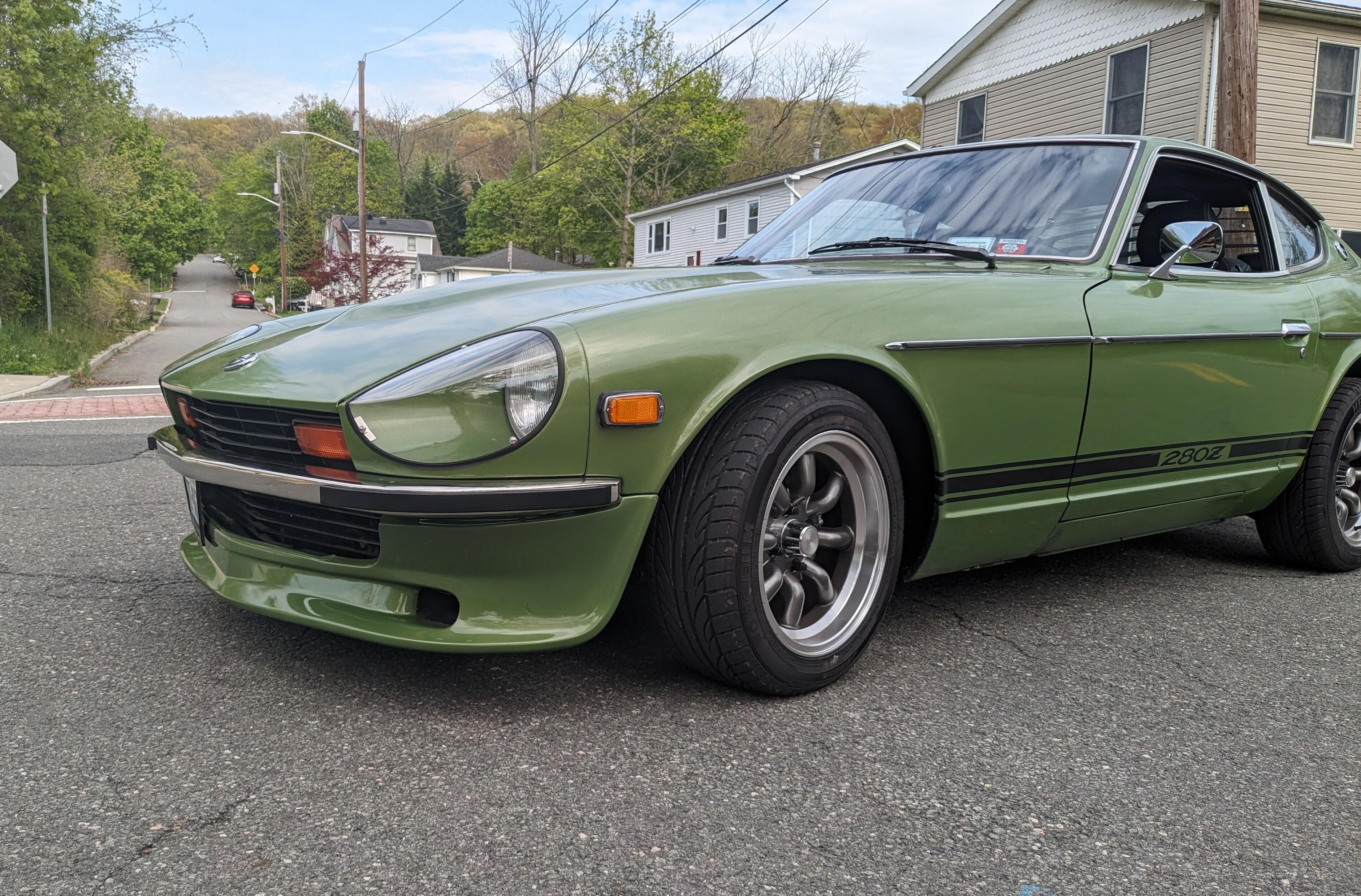
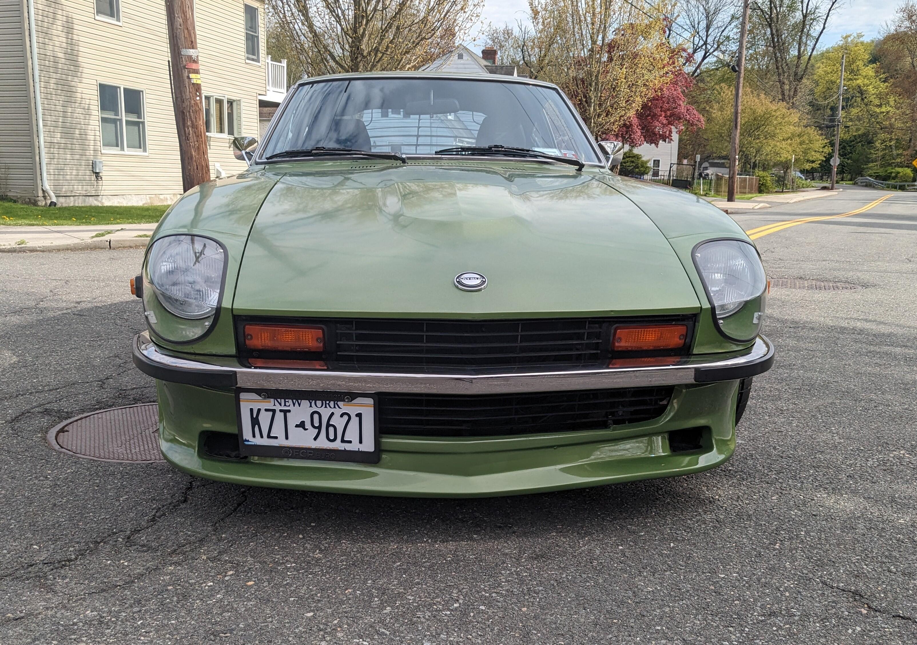
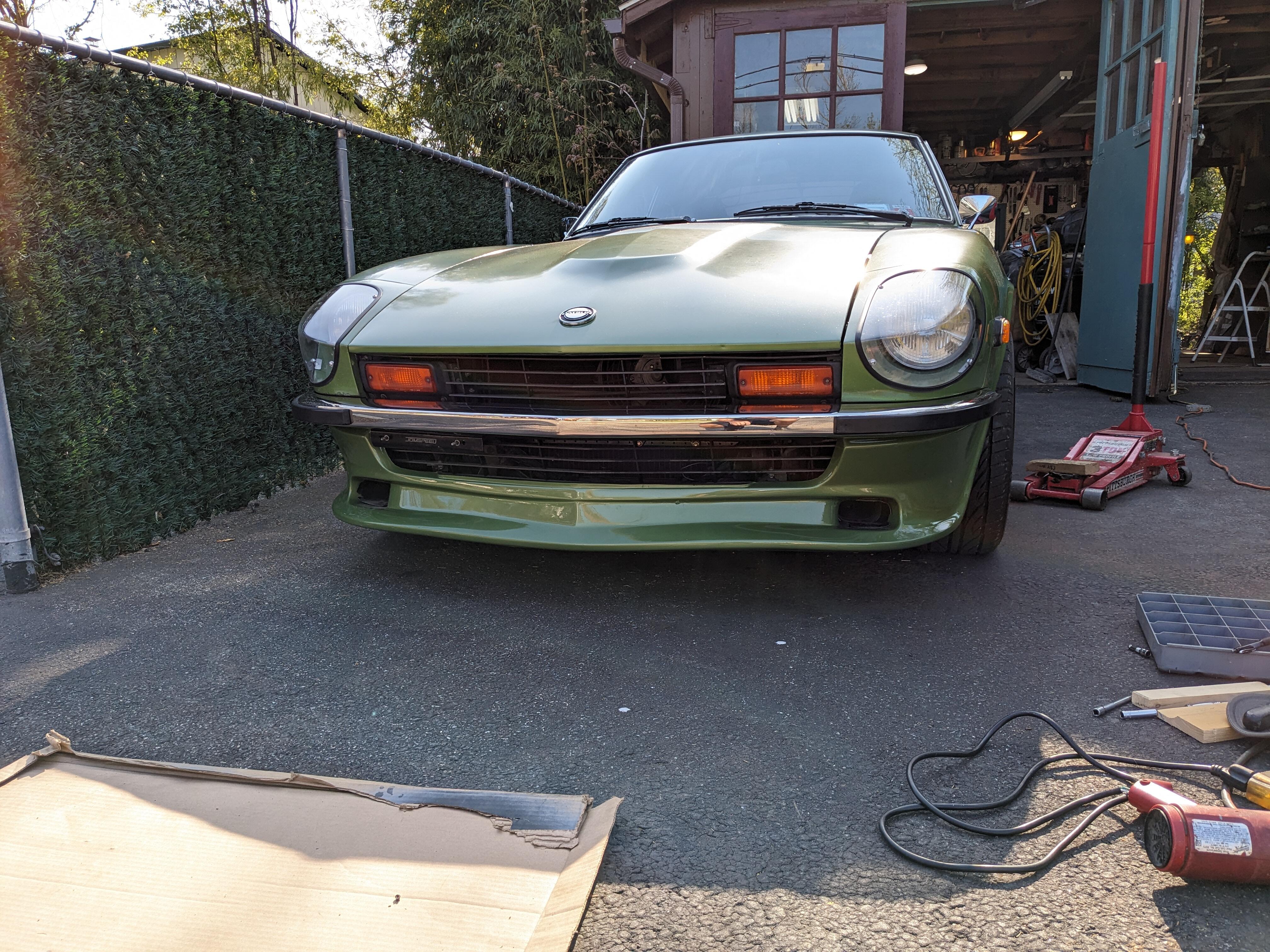
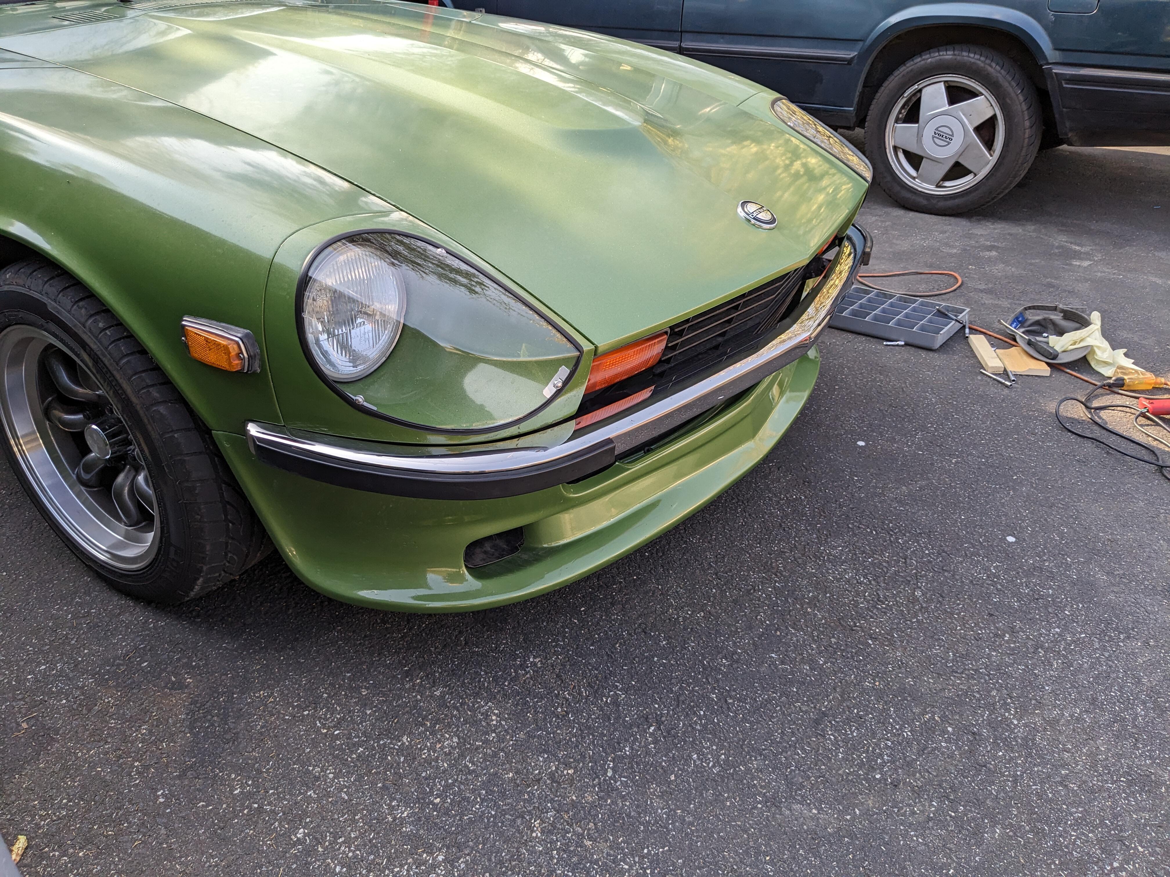
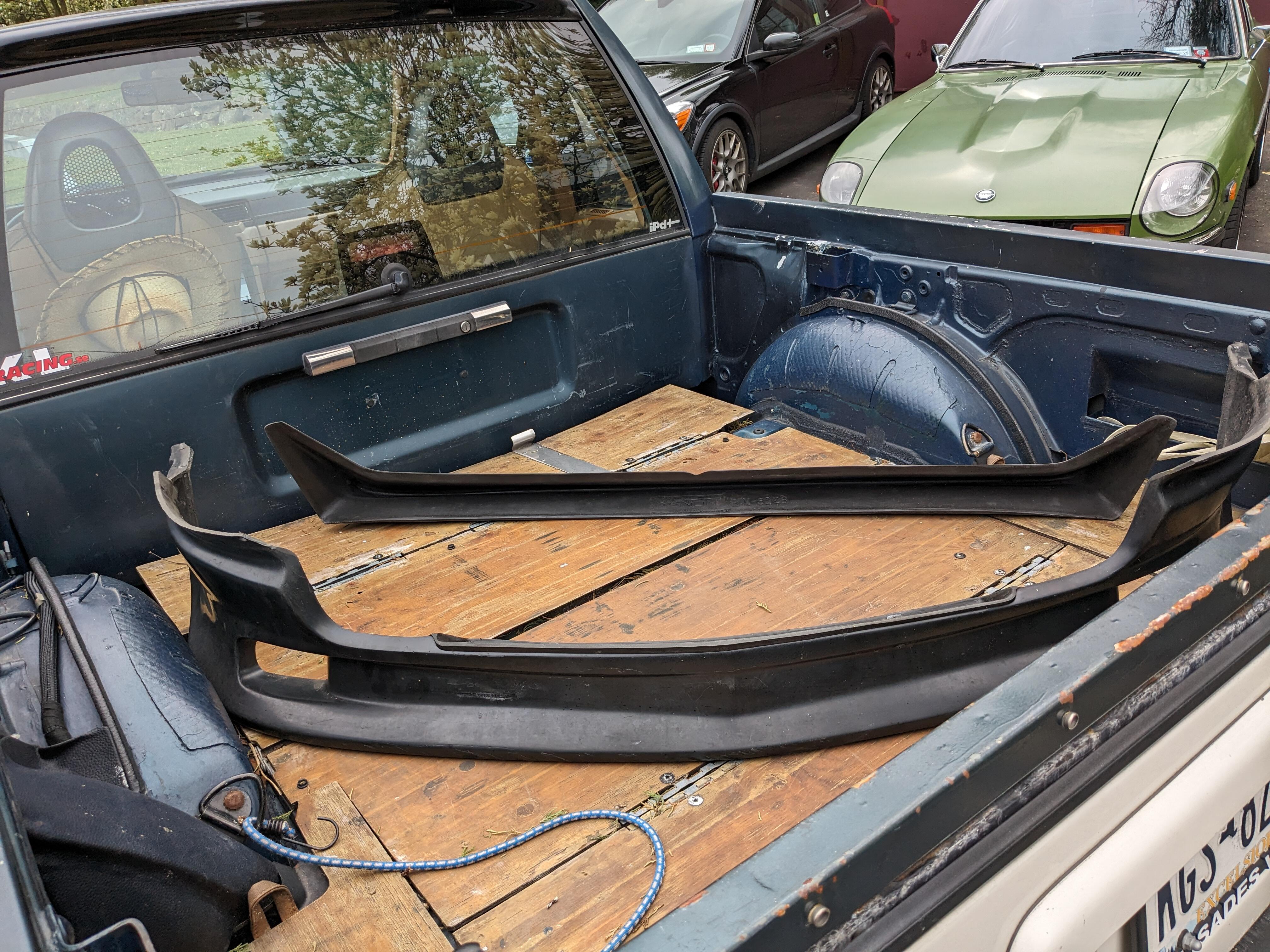
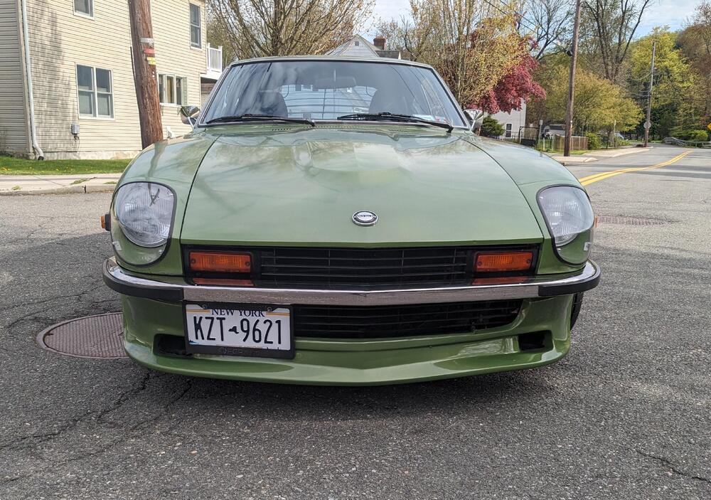
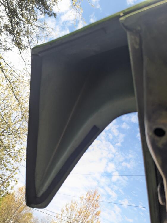
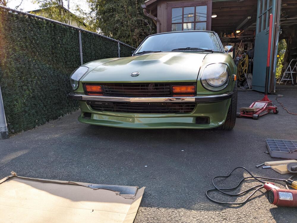
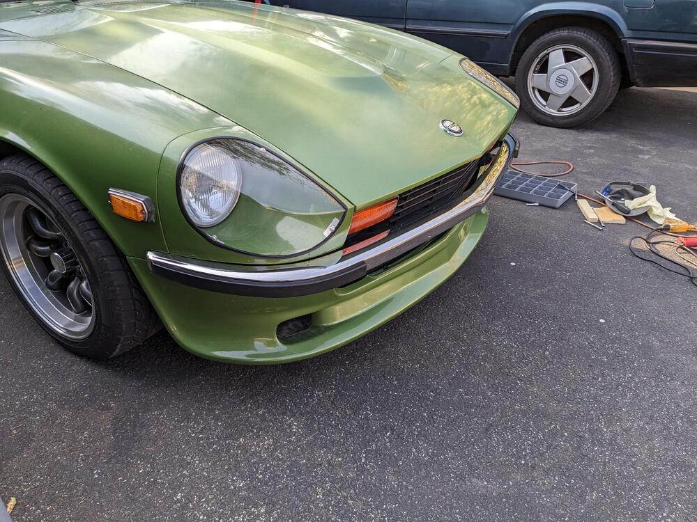
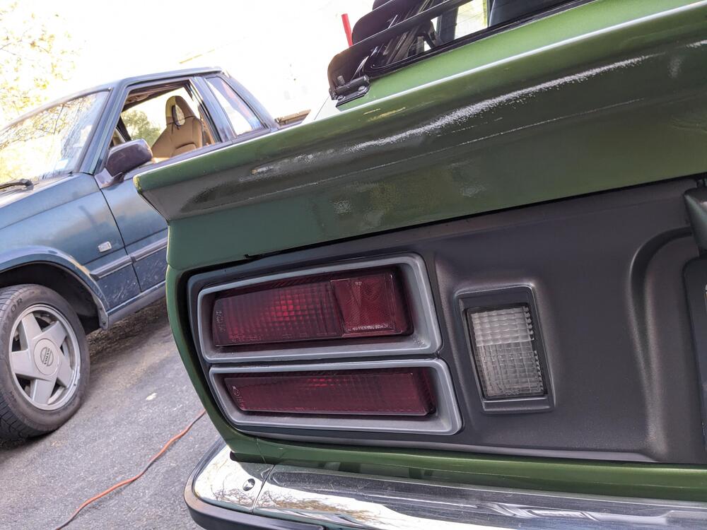
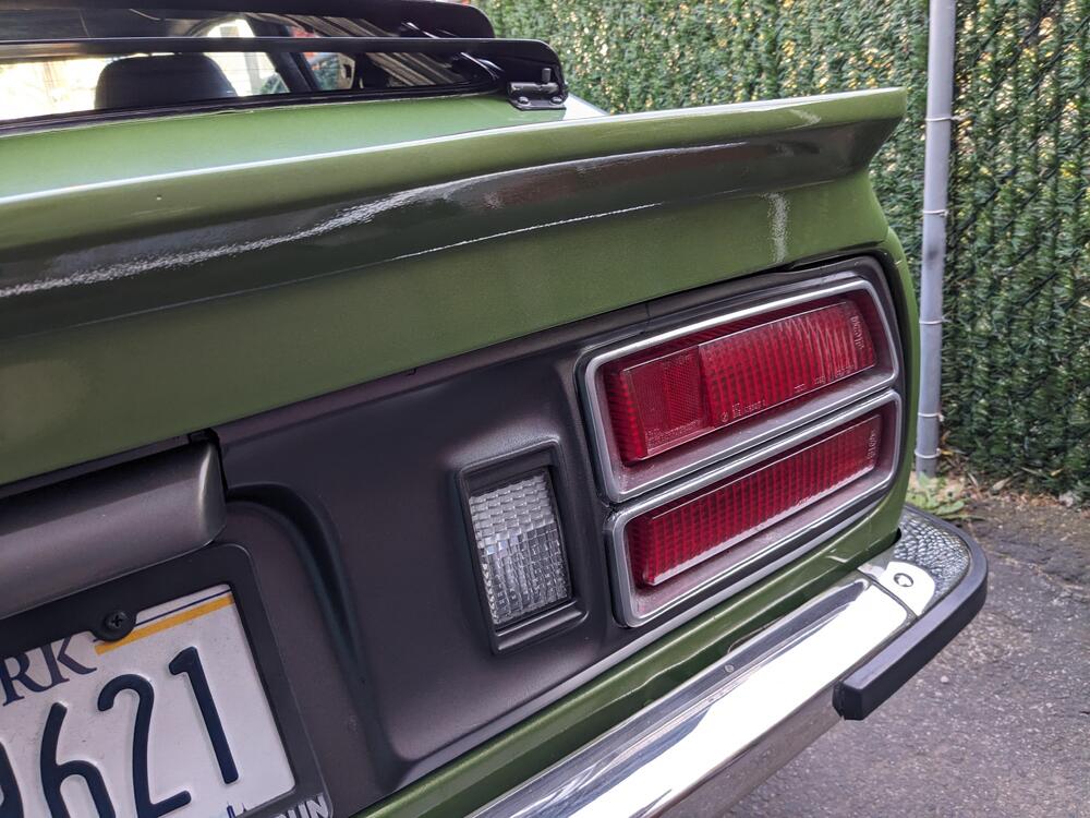
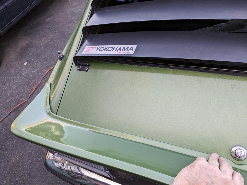
Put the painted Xenon front spoiler back on - that was a pita - either the thing shrunk in paint, or something - I had a hell of a time getting the holes to align. There is a wave in the left lower that wasn't there previously, I'm going to have to heat the crap out of it & see if I can relax that . Happy with the color match at least The rear spoiler is a $^!# show - it's completely deformed, in this picture I'm pressing it in place to get it even close. And the left and right are not the same. It doesn't come with specific fit instructions, that would indicate which surface to align with. As a result I don't know how deep the top is supposed to be? Whether it's supposed to be tucked right under the lock or further back from it no way to tell for sure because nothing aligns. This is problematic as it is supposed to be installed with double-sided tape. That doesn't work very well if you have to maneuver the spoiler at the same time as sticking it in place, in fact it's not going to work. Xenon has no pictures of one installed on their website.
-
OK - I typically replace line clamps with Oetiker clamps for anything that doesn't require routine service.
-
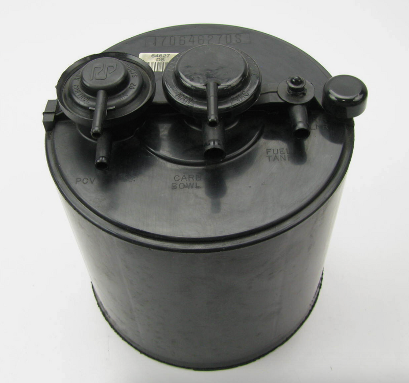
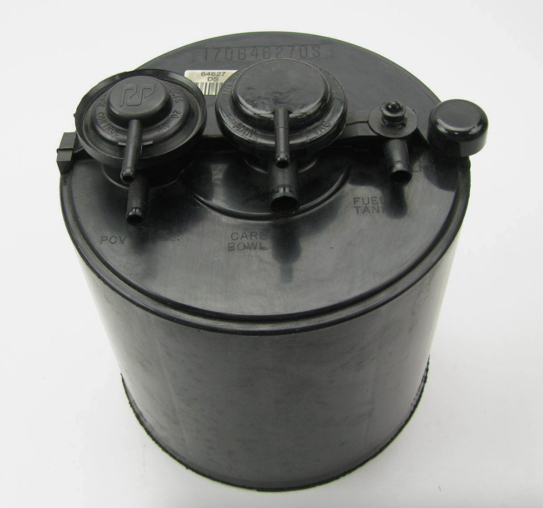
apologies - I didn't see the question - yes, that is what I would do there. EDIT - actually I think you would add a vacuum line. The ports are listed PCV - Carb - Tank, so I think all three would be used. I'd look at a GM schematic for the model it's intended for. When you say belt clamps, you mean the hose clamps?
-
Had to get several things squared away on the truck - it's annual state inspection is due. Main thing was the tail lamp connections - since I drove it for a year with no covers over the back of the tail lights, the sockets had all got crud on them, and sometimes the indicators would come on through the brake light circuit and so forth. All indications of bad grounds. I have several new bulb sockets, so I dug those out and cleaned up the connections on the tail light circuit boards. Besides that it was just odds and ends that they would look at as part of the safety check. I got it inspected this evening, no problems there thankfully. Since I didn't have a lot of time, I focused on making a rack to store the wood that I had outside - the tarp I was using seen better days, and wasn't keeping the water off the wood. So I had to clean and dry them all . Figured it would be safe it to store them indoors. I used pieces of tubing from the canopy I had used to cover the X1/9 when I painted it back in 2018, and set those in the angle iron with six of the longer Fiat head bolts (welded in place)
-
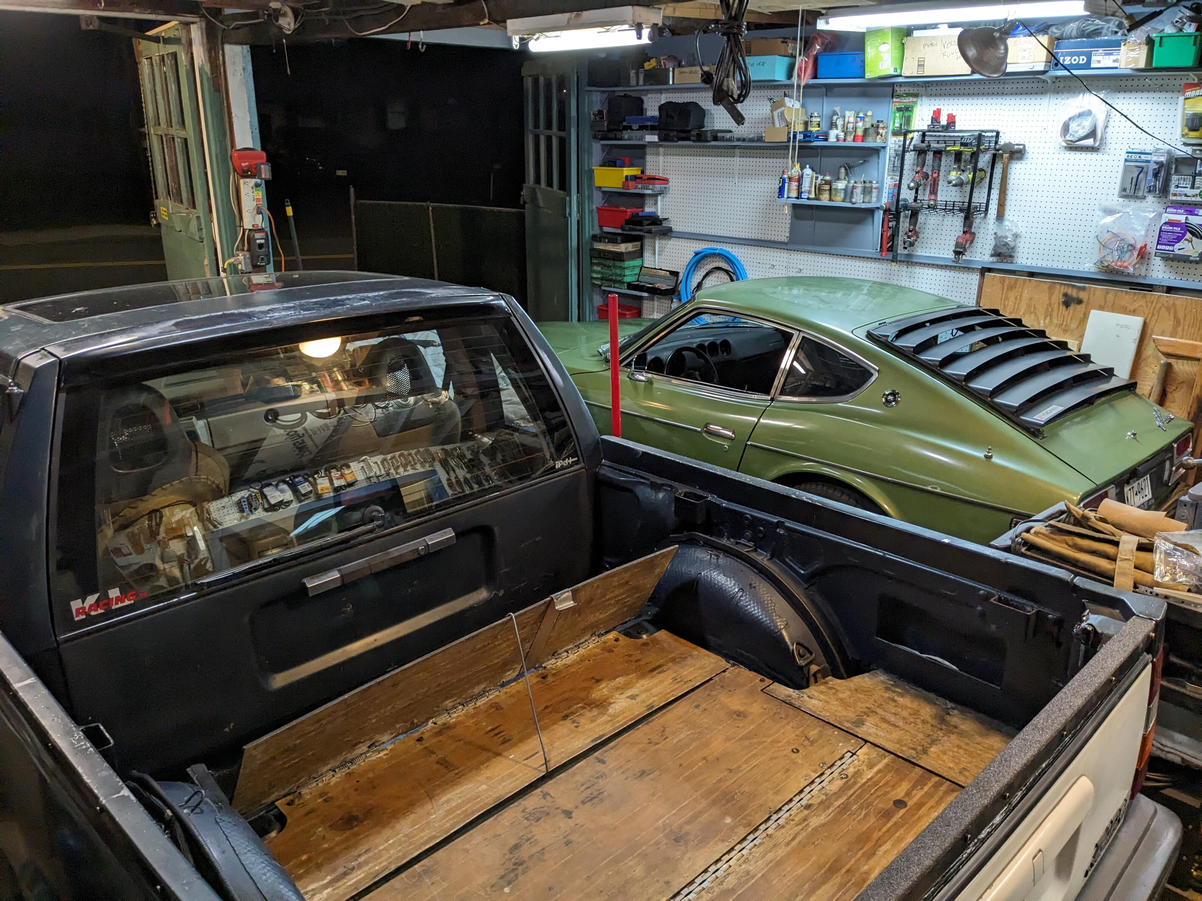
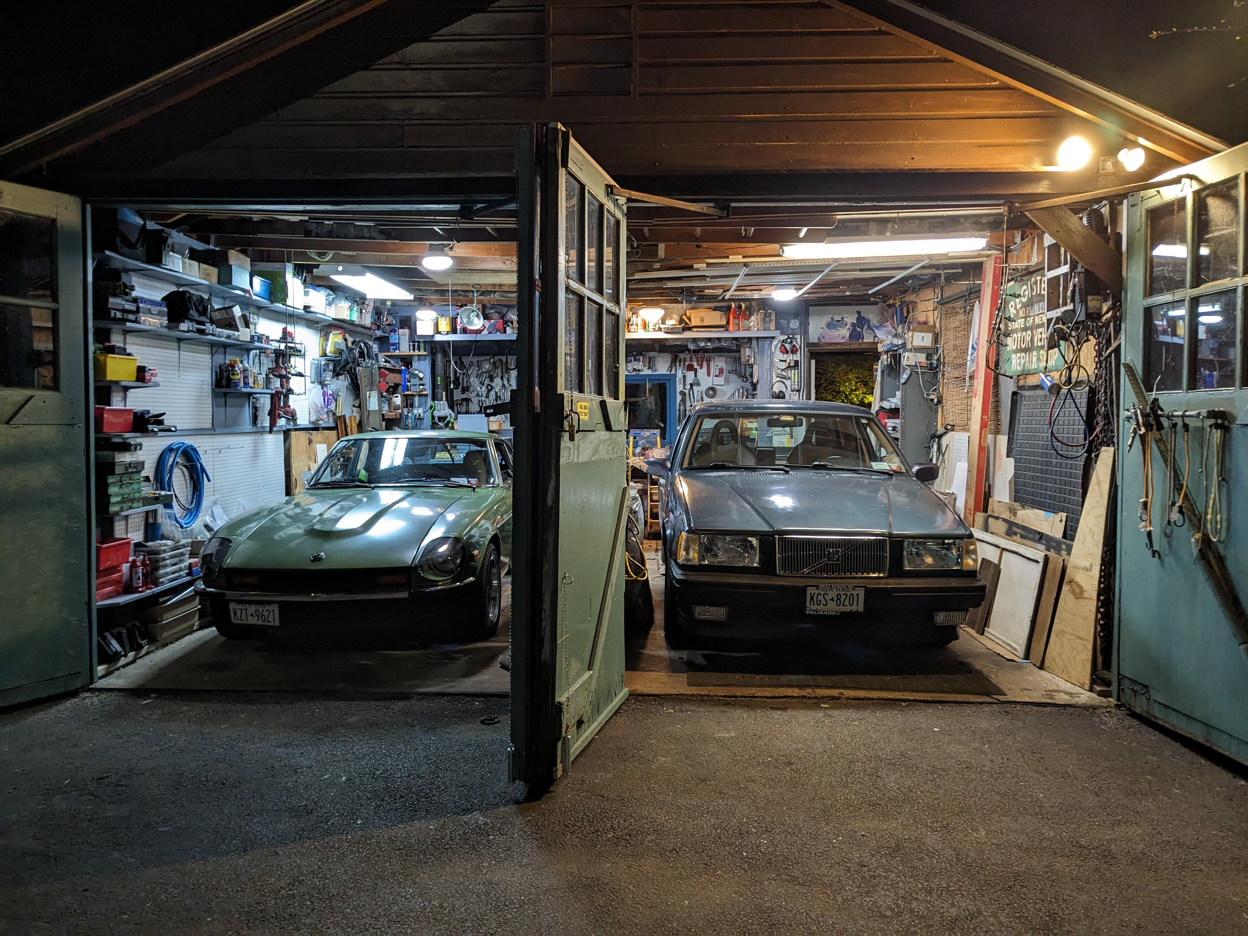
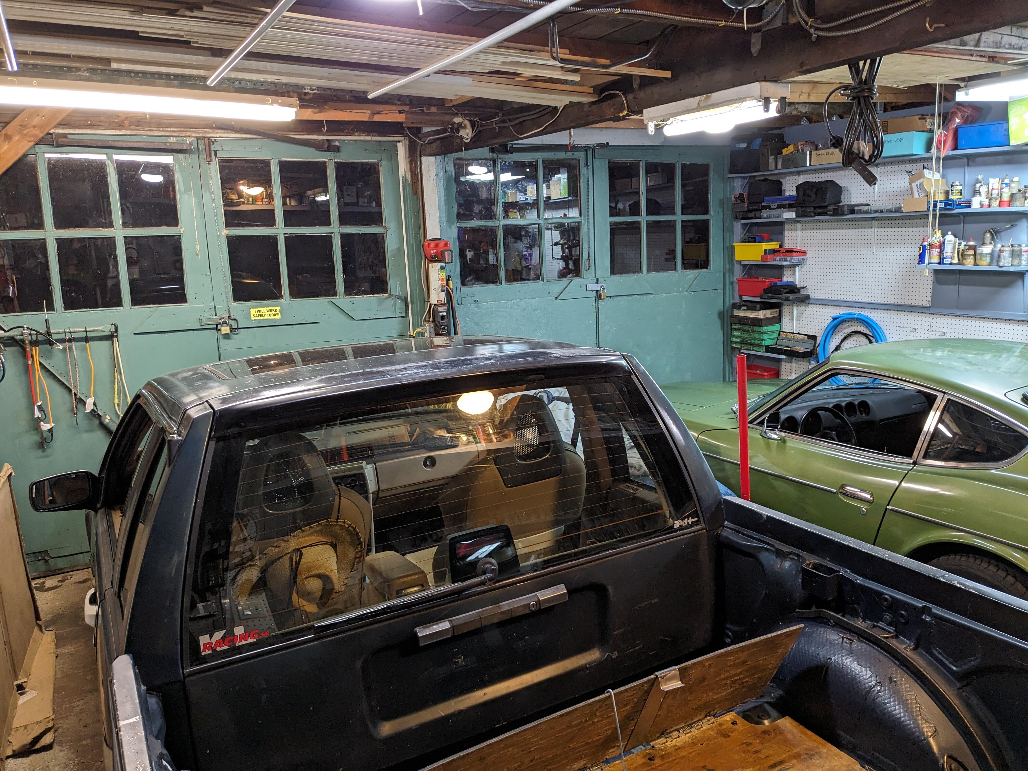
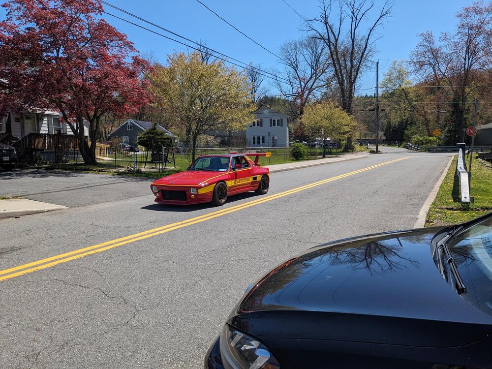
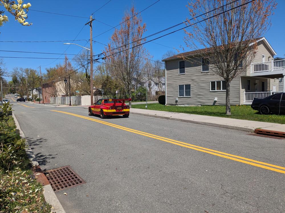
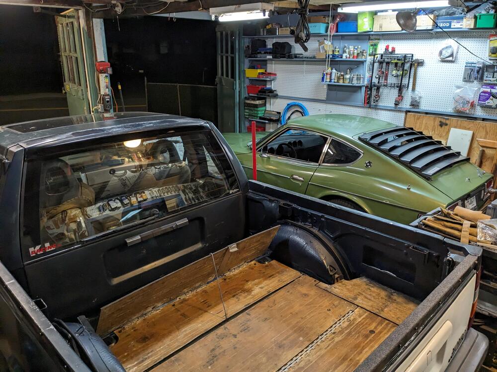
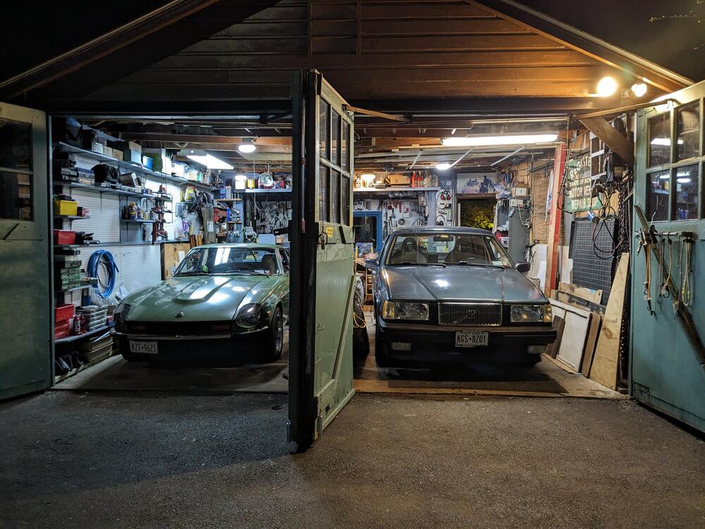
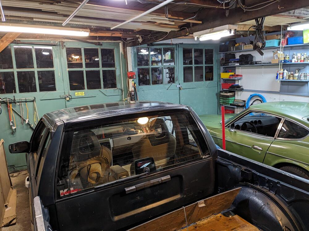
Fiat is now gone, making space for the pickup alongside the Z
-
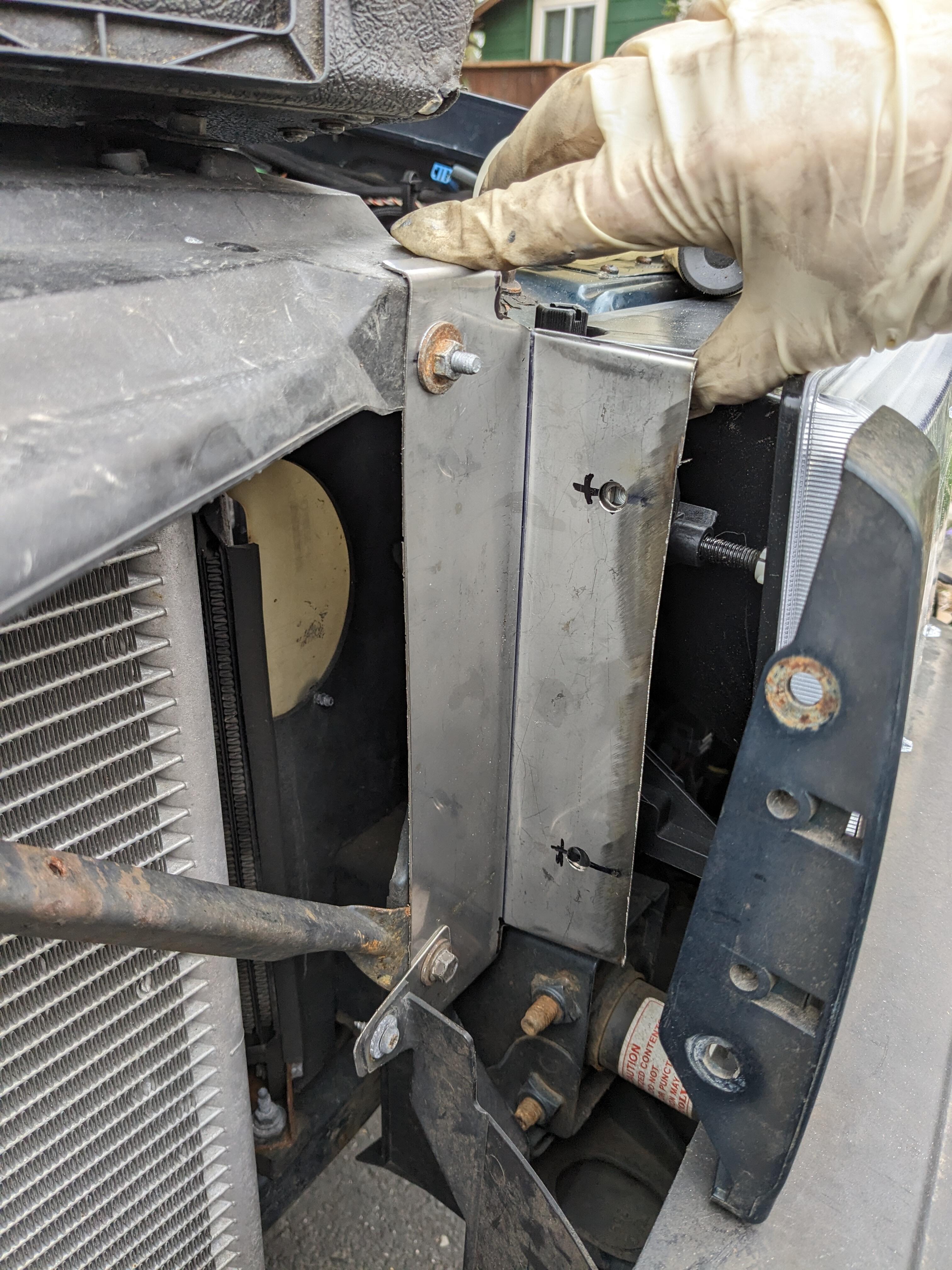
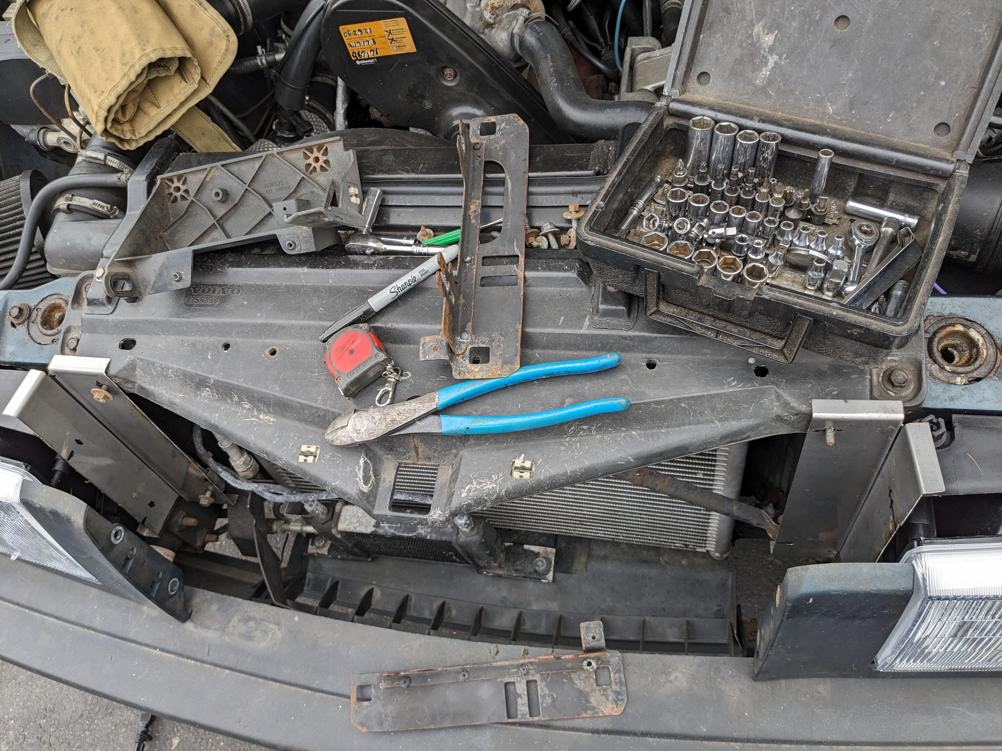
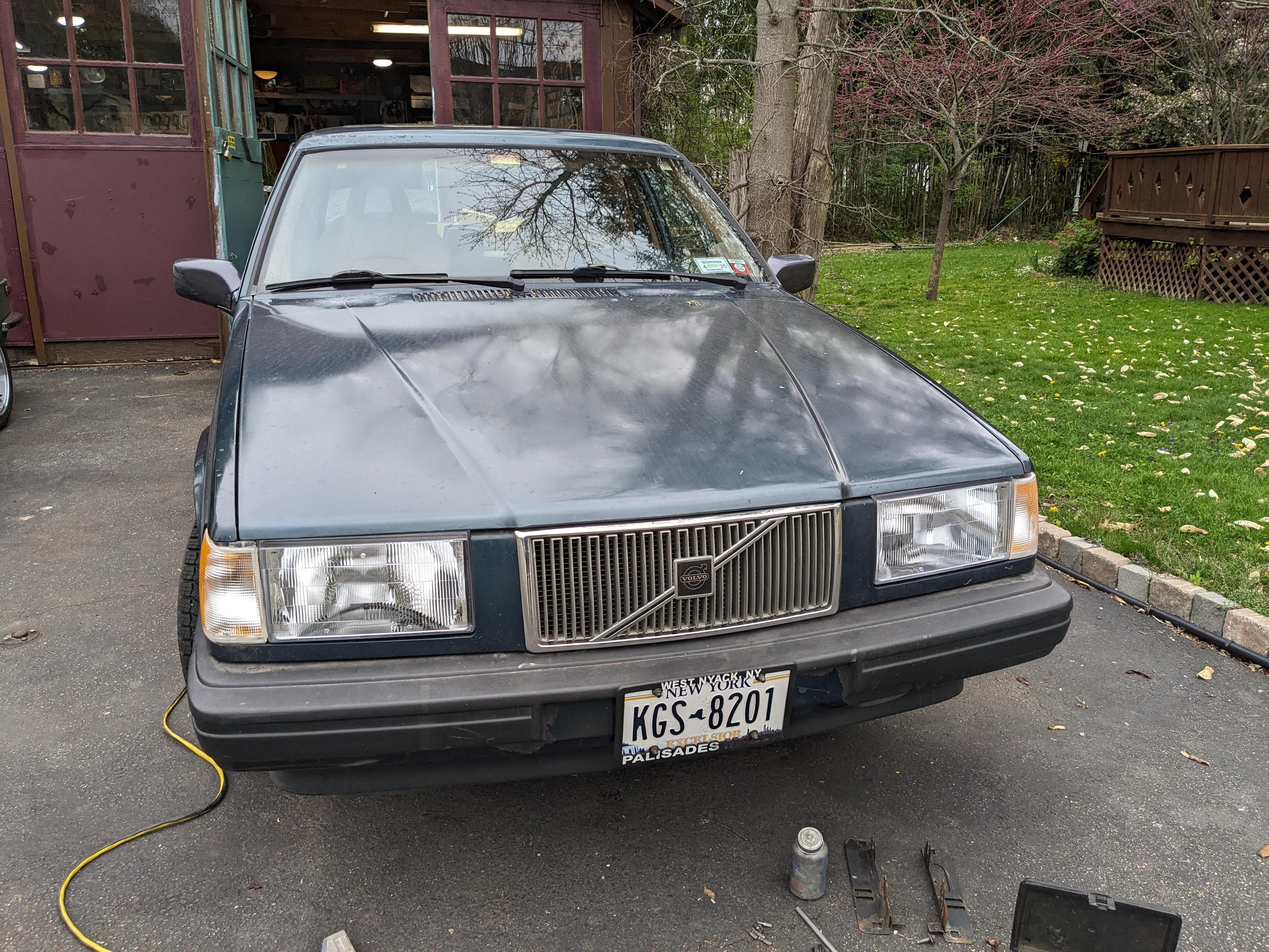
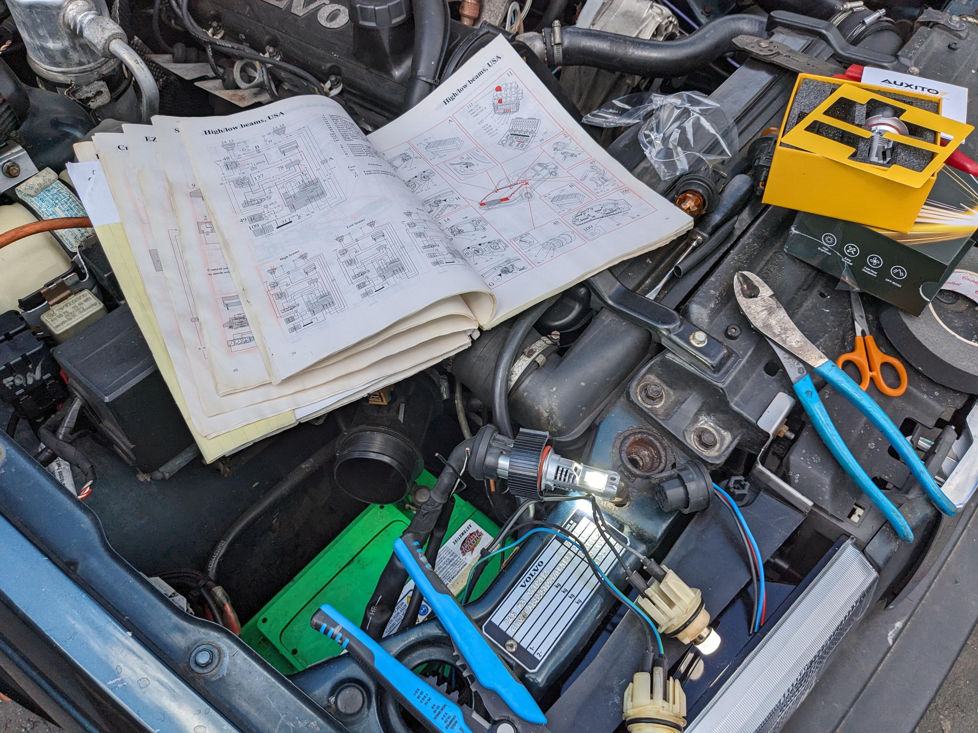
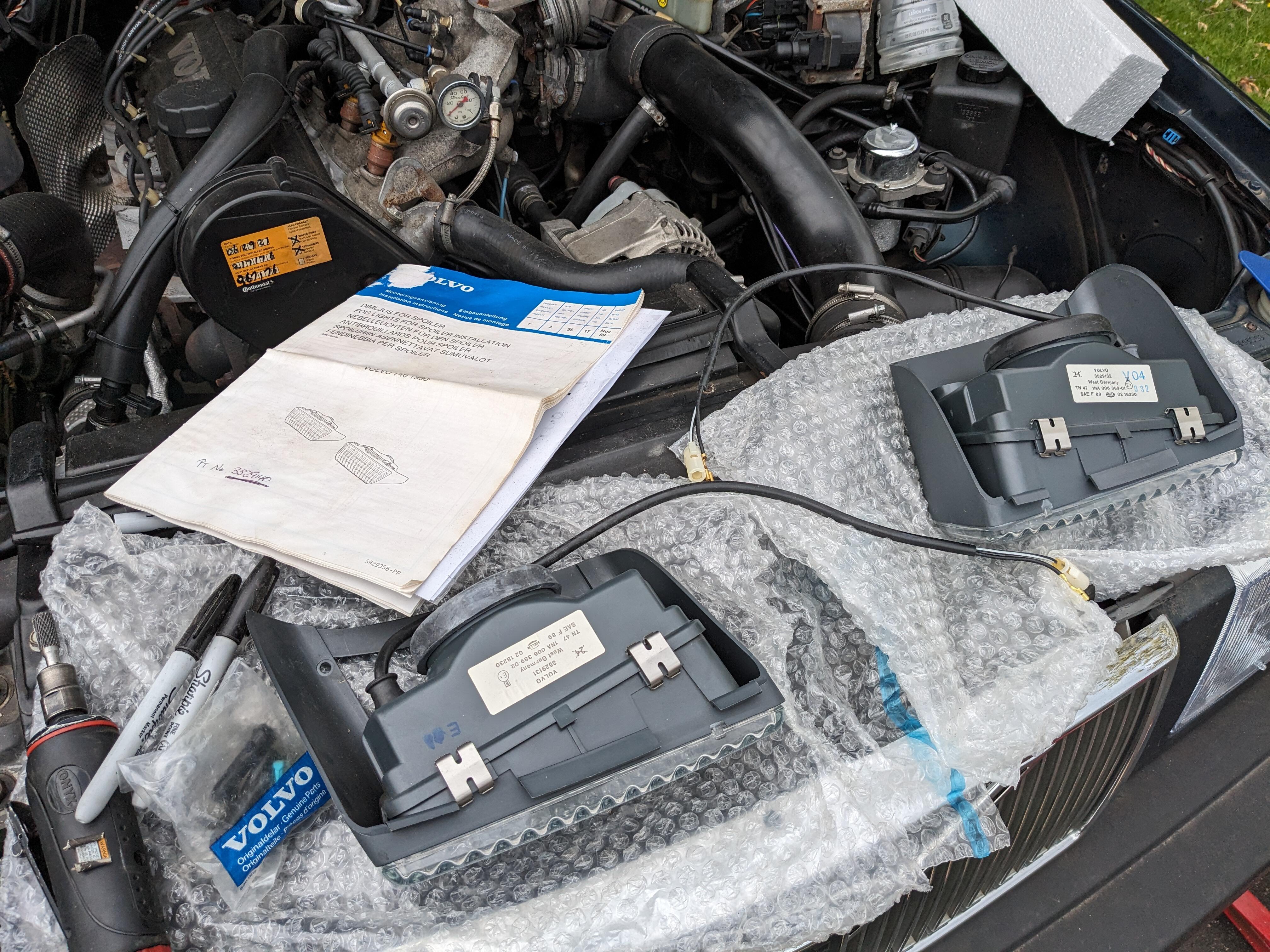
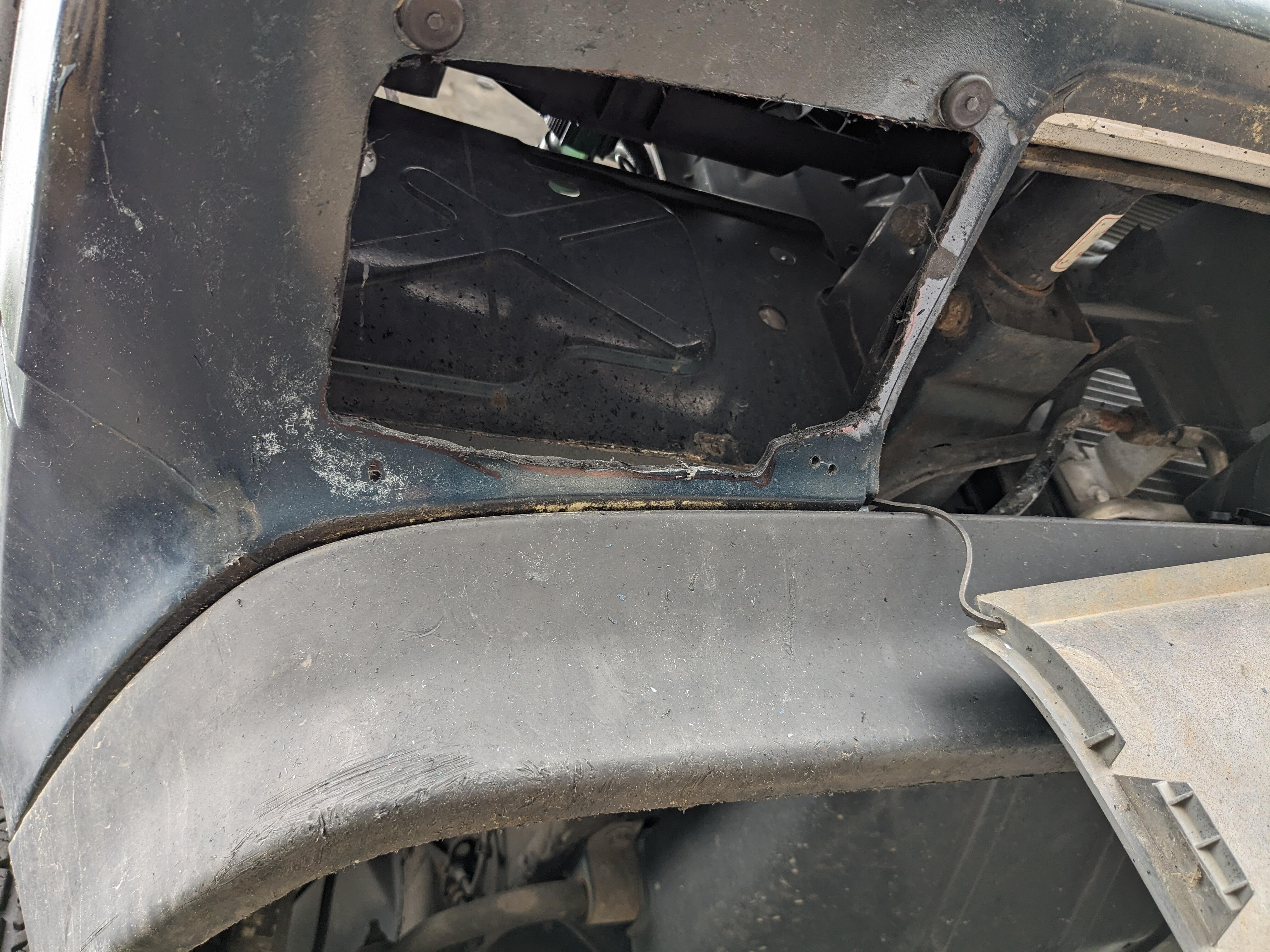
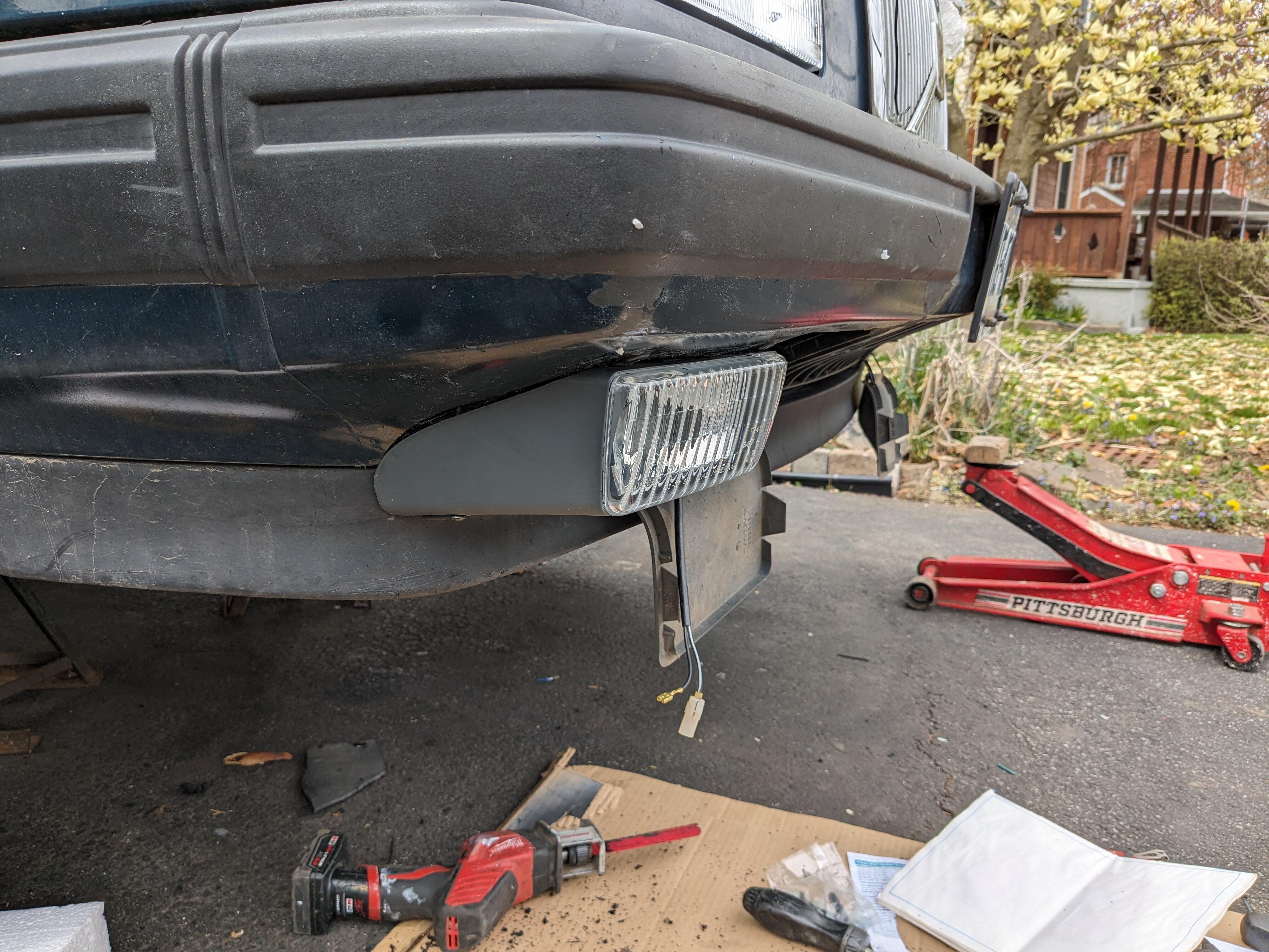
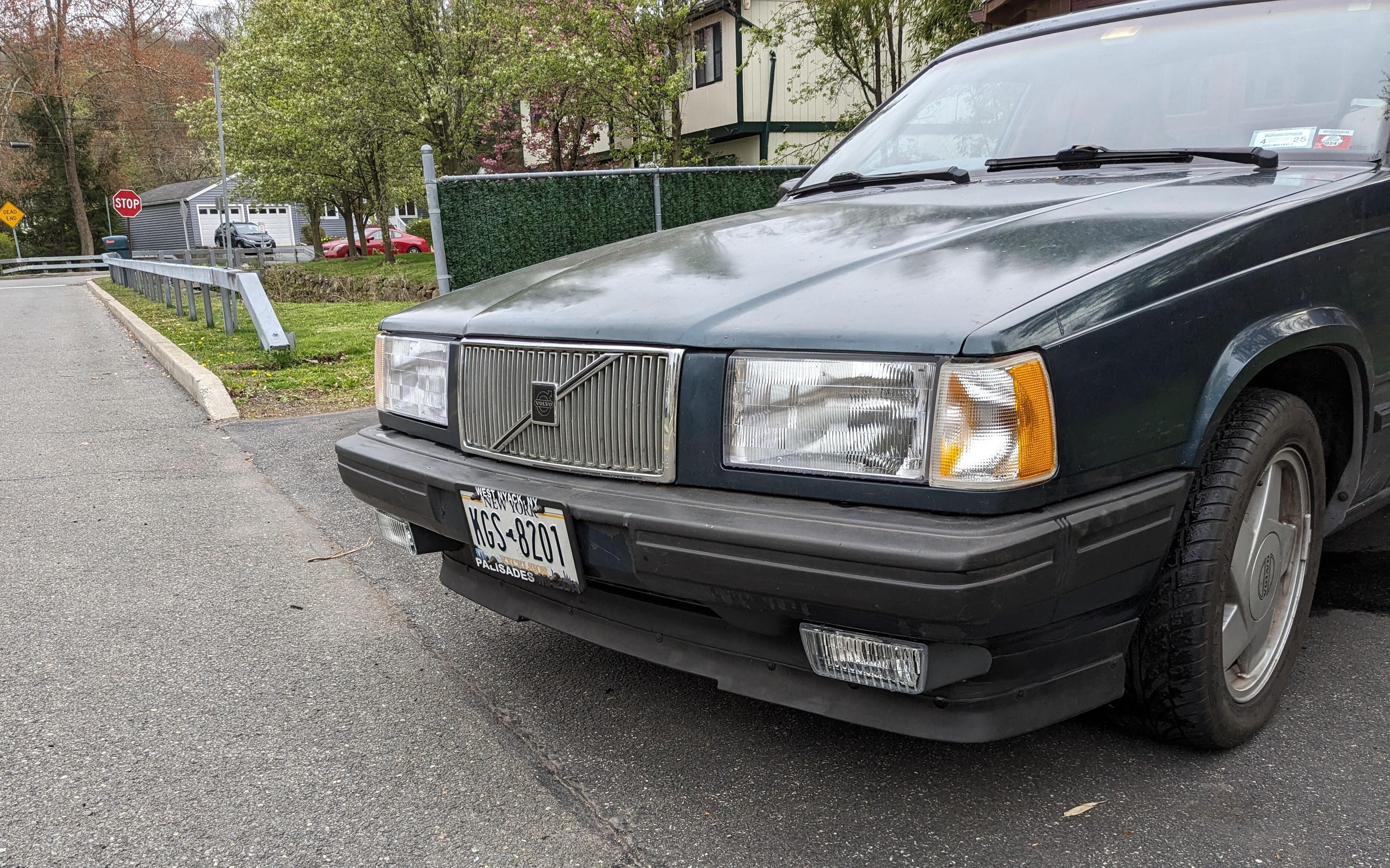
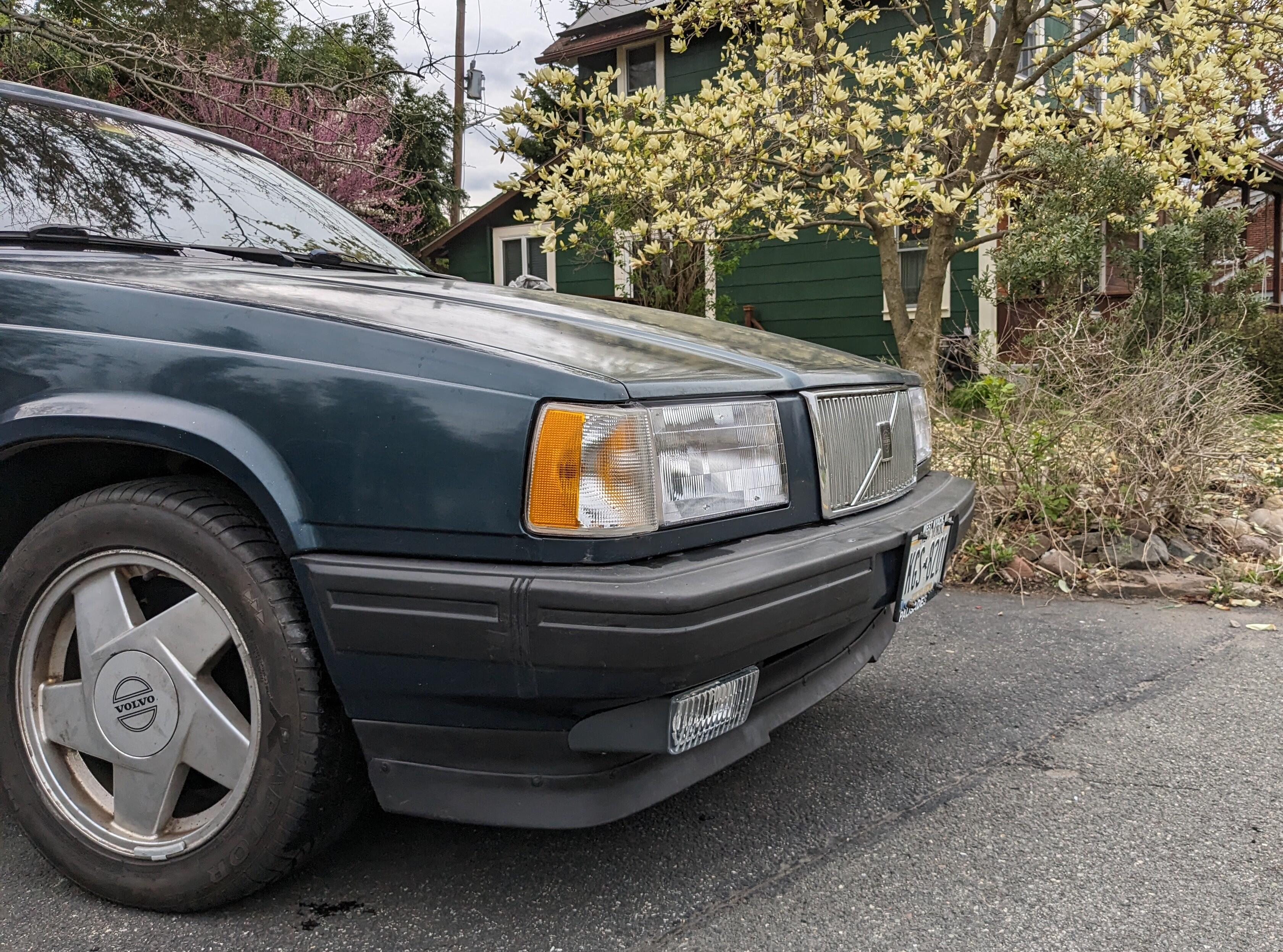
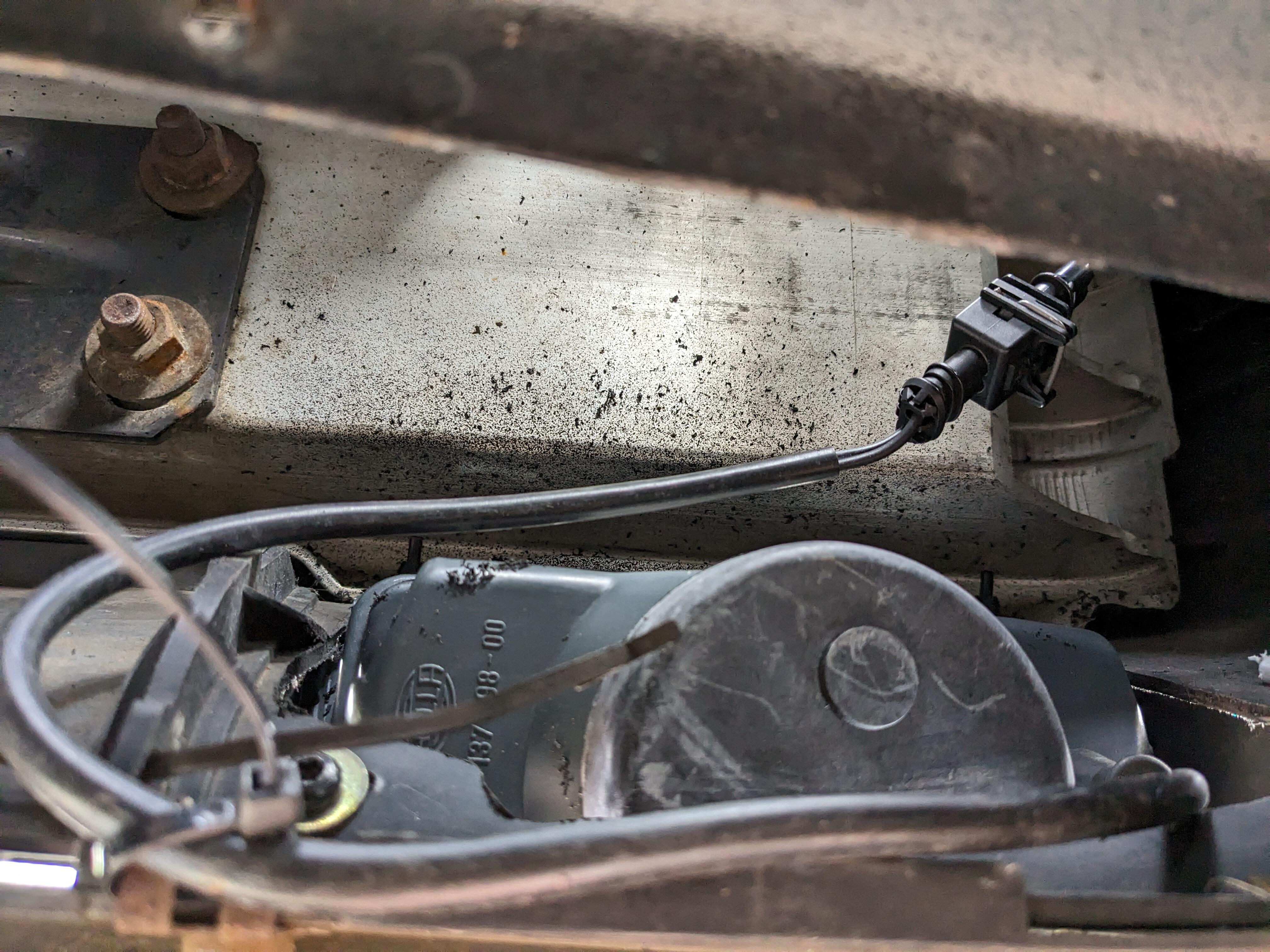
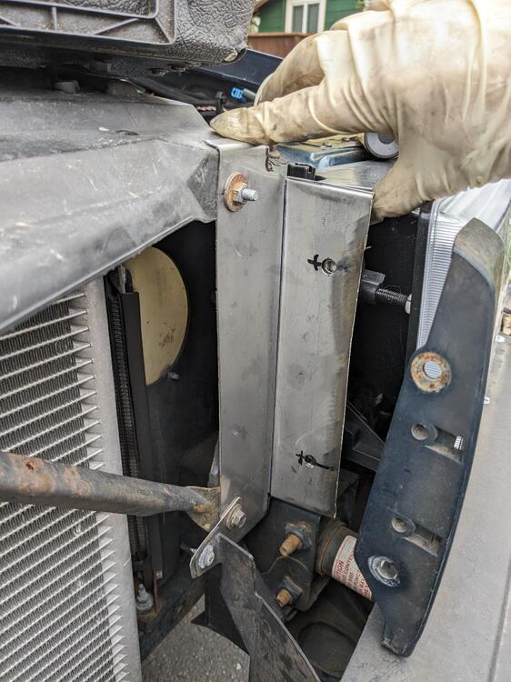
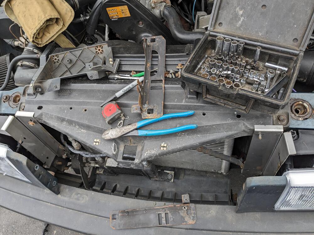
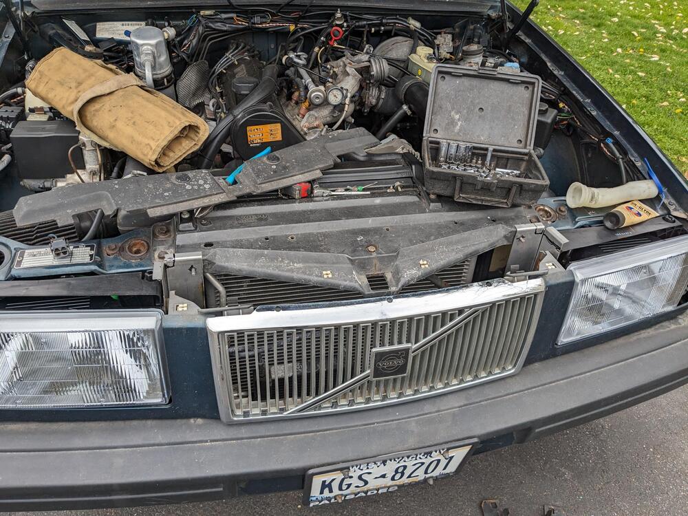
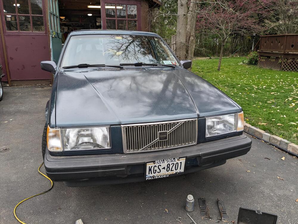
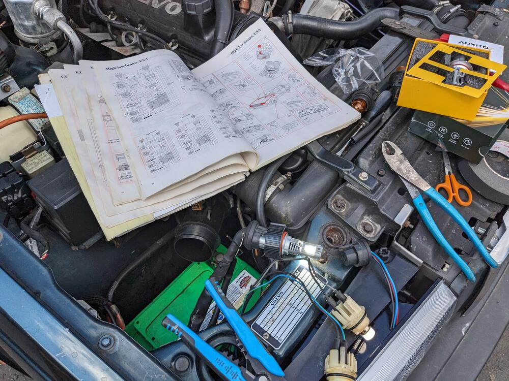
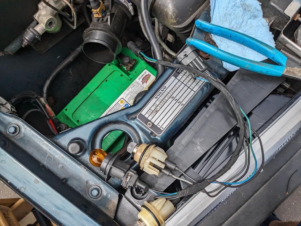
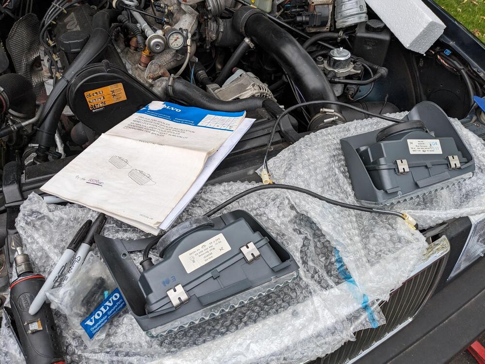
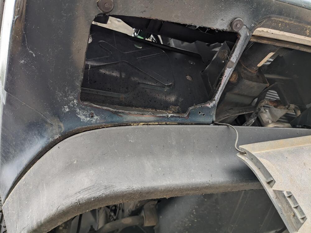
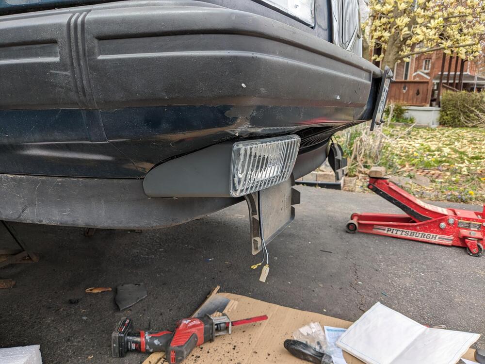
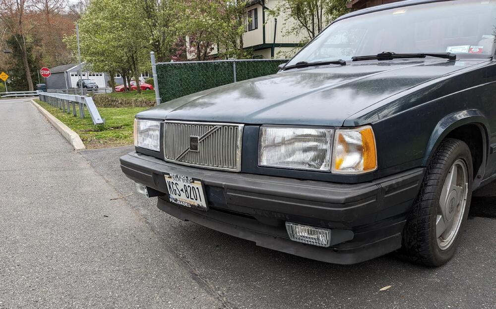
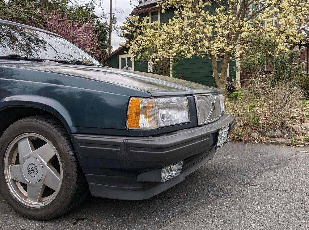
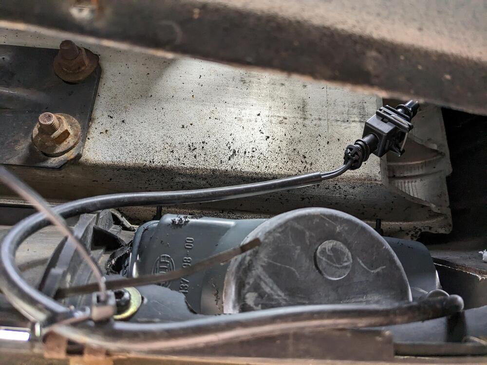
Another side step while I'm waiting for the Z spoilers to get painted. On the 740, I reverted to the original headlamp arrangement - these have plastic lenses vs the glass of the EU version I had installed a couple years ago, however they are much easier to get the beam properly adjusted. Also added the factory fog lamp kit I bought a couple years back. Had to make new support brackets for the lamp units , also used to anchor the grille brackets Test fit alignment Rewiring for the US spec bulbs & sockets NOS foglamp kit Cut opening using provided templates Anchored harness just case bracket gets hit
-
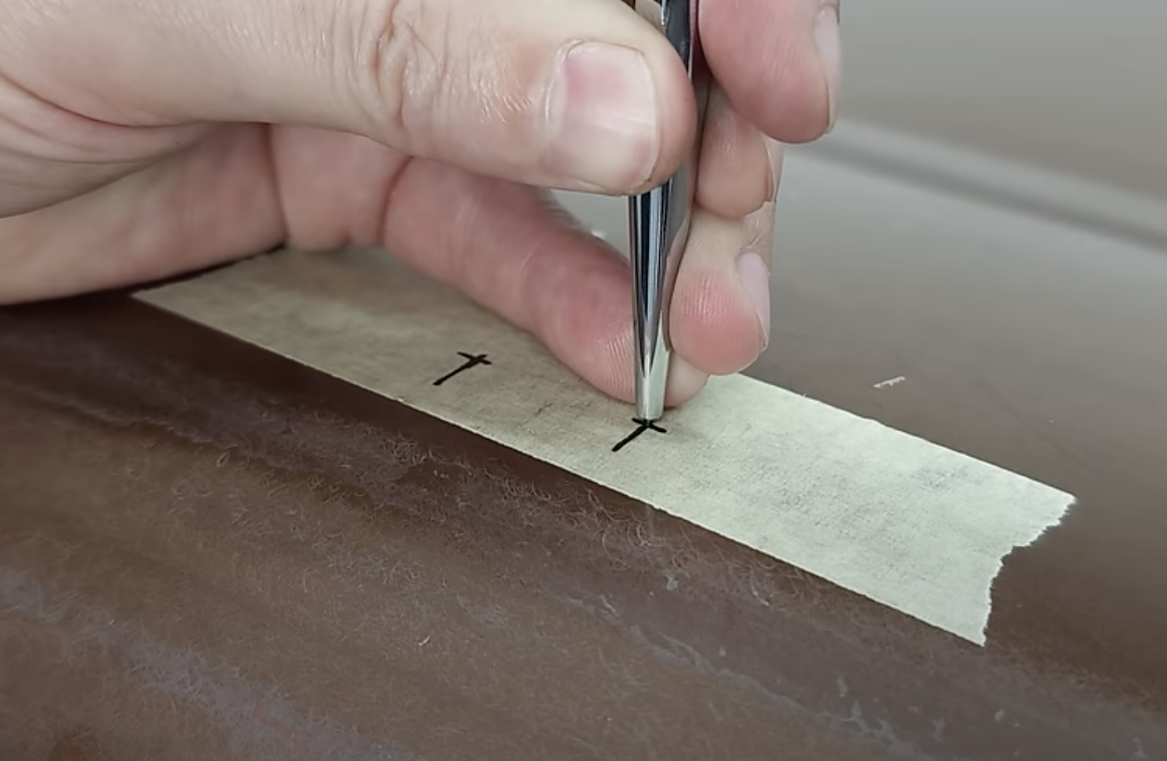
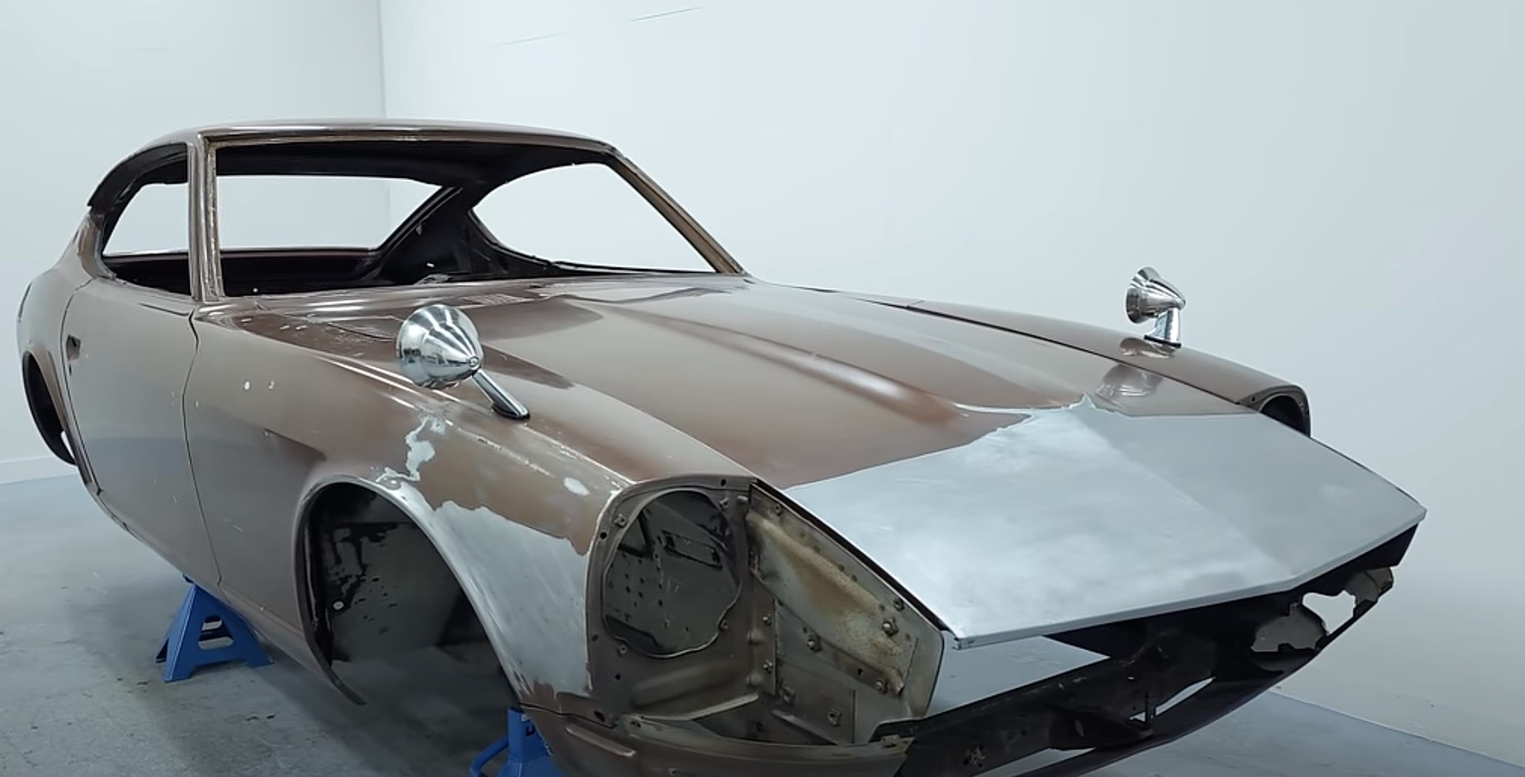
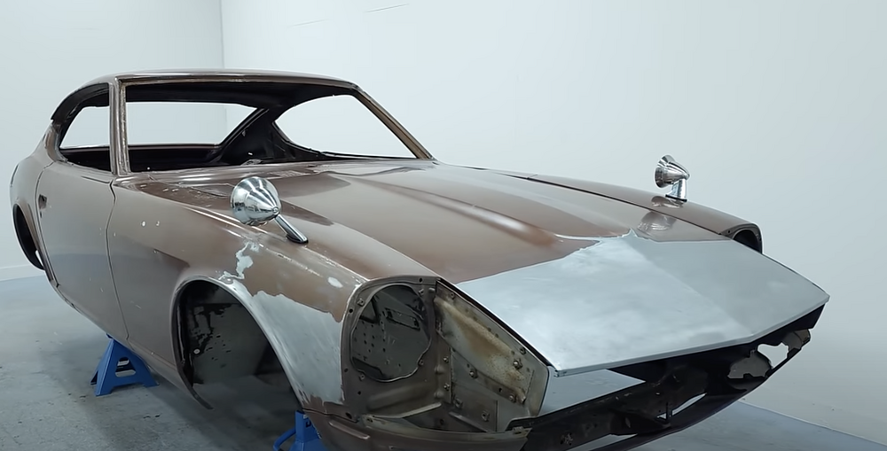
Thank you for the links! I do wish someone had actually photographed their car with the physical hole location when they did it, vs. a diagram of where to place the base gasket. Not one of the threads actually has any install pics besides the diagram. I'll have to add mine when I do them. One guy adjusted it for LHD There is a very meticulous YT Z restoration video ongoing series - I took screen shots from his Pt. 2 video (rightside, LHD chassis)- but he only shows one side & can't tell if he made them asymmetrical - I guess he'll find out if his are not right DTR
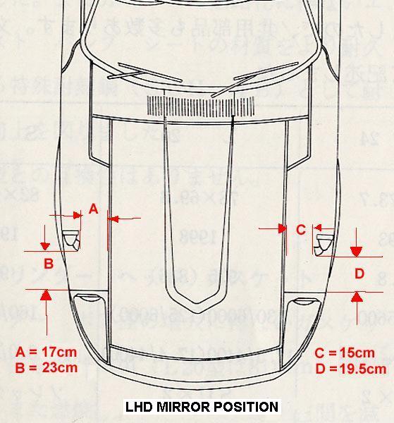
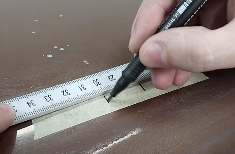
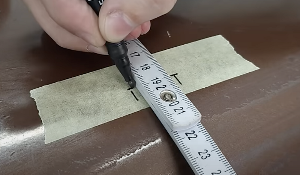
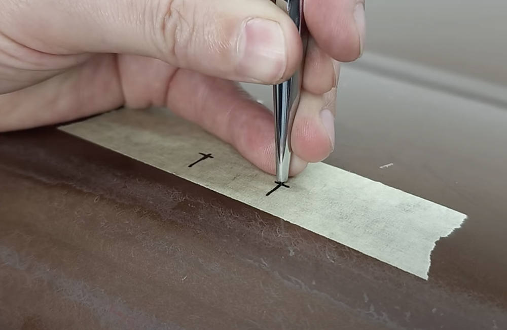
-
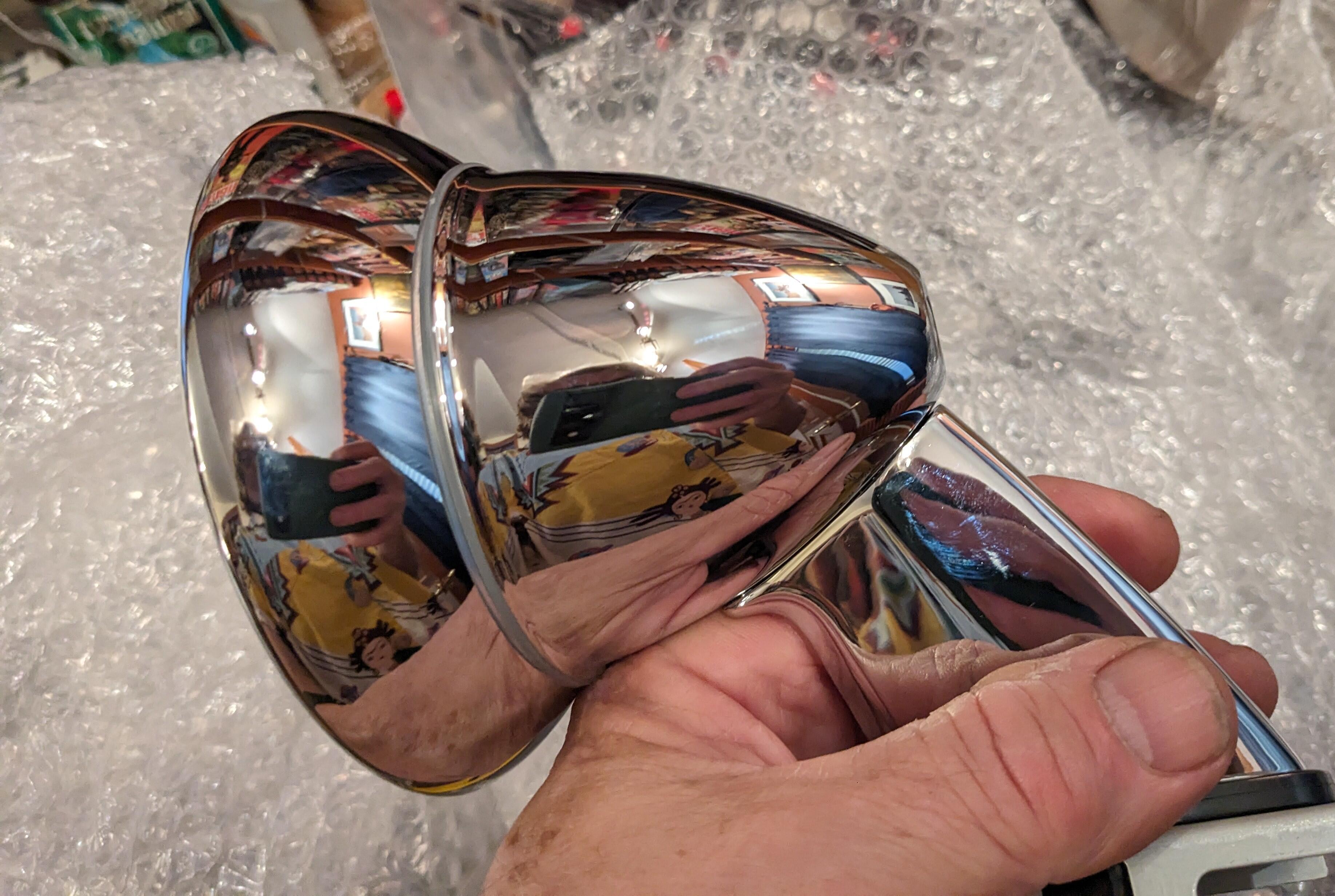
Another item arrived for install DTR - I will have to fill & paint the door caps for this job, do I'll likely do it in conjunction with the later window frame mod. If anyone has a link to the precise location for installation, I'd appreciate it immensely😀

-
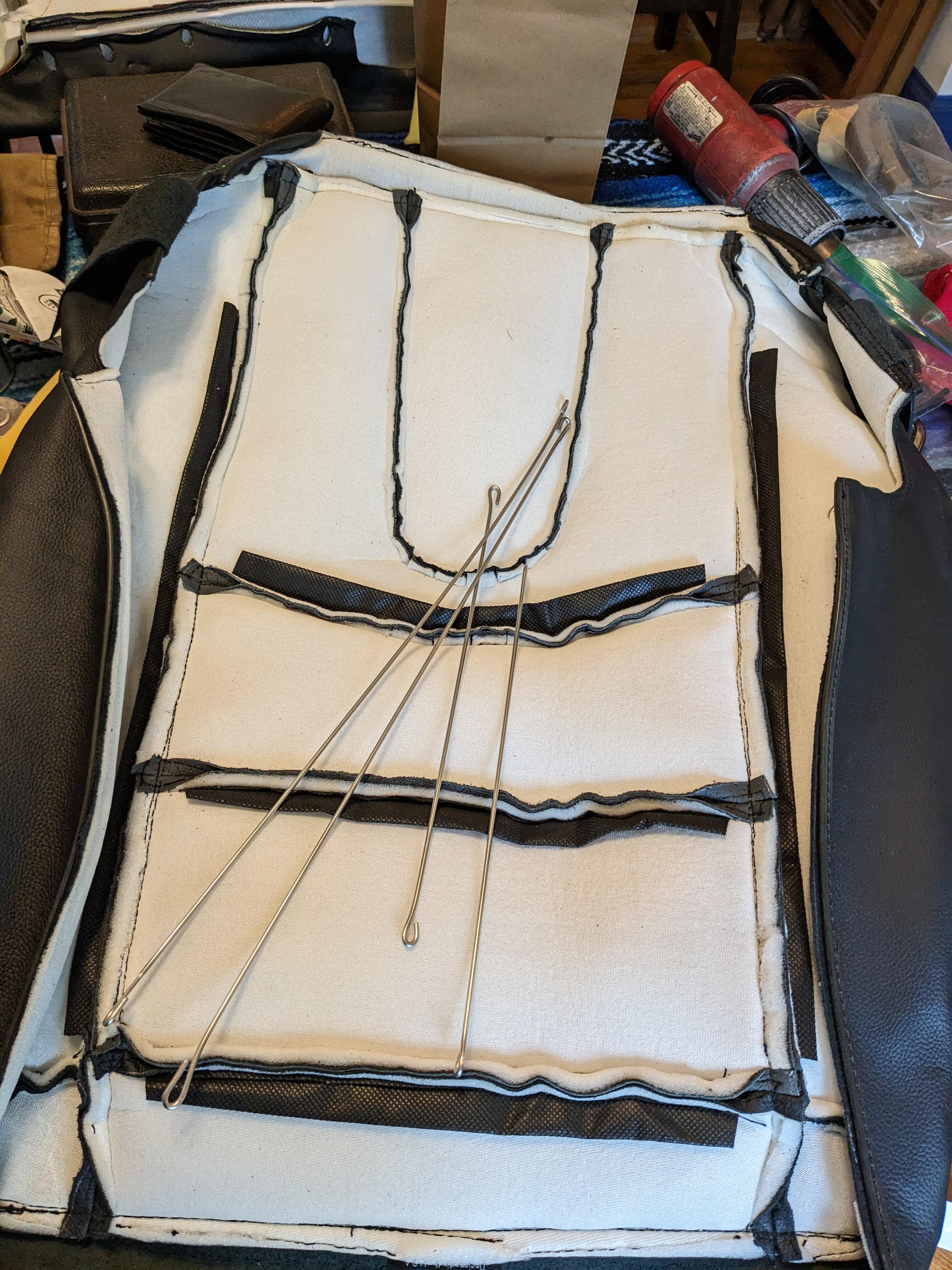
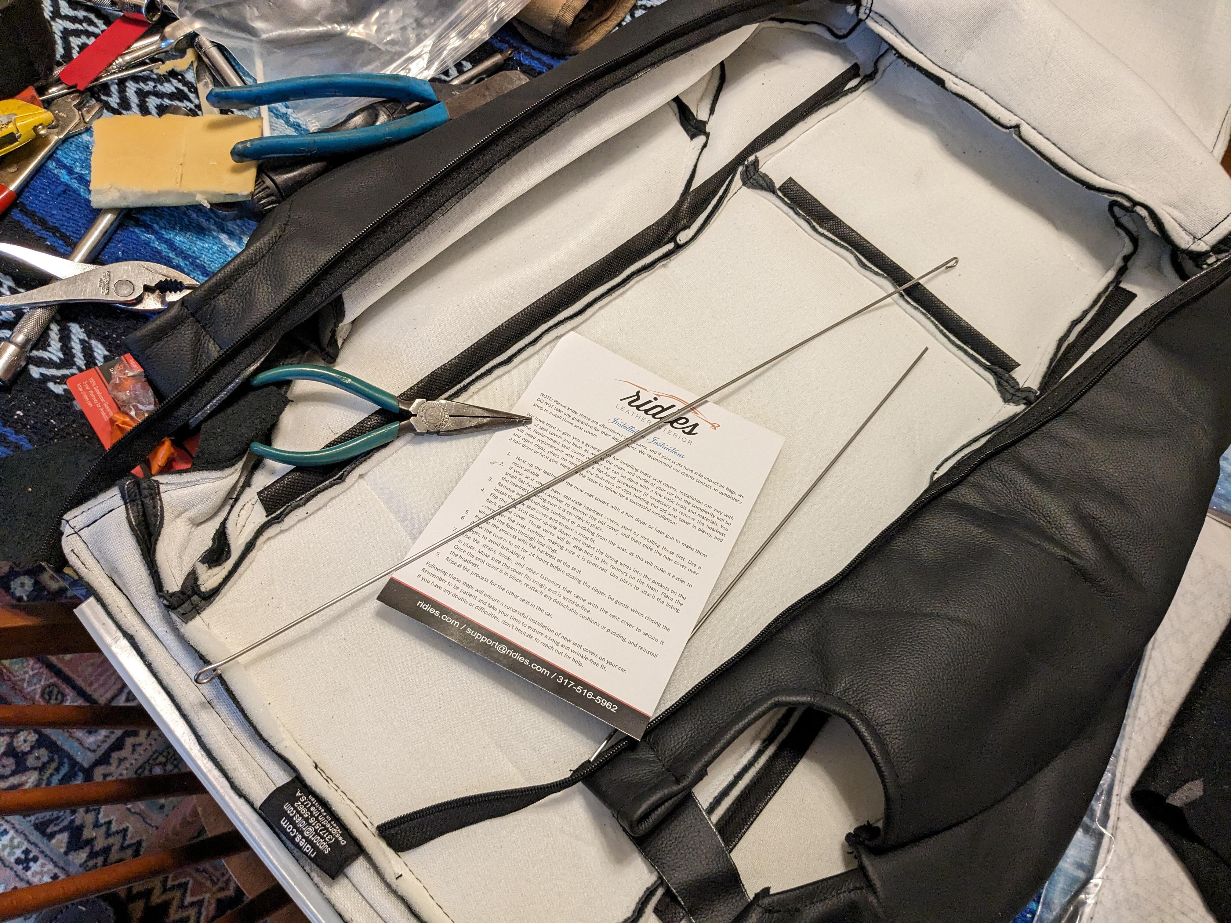
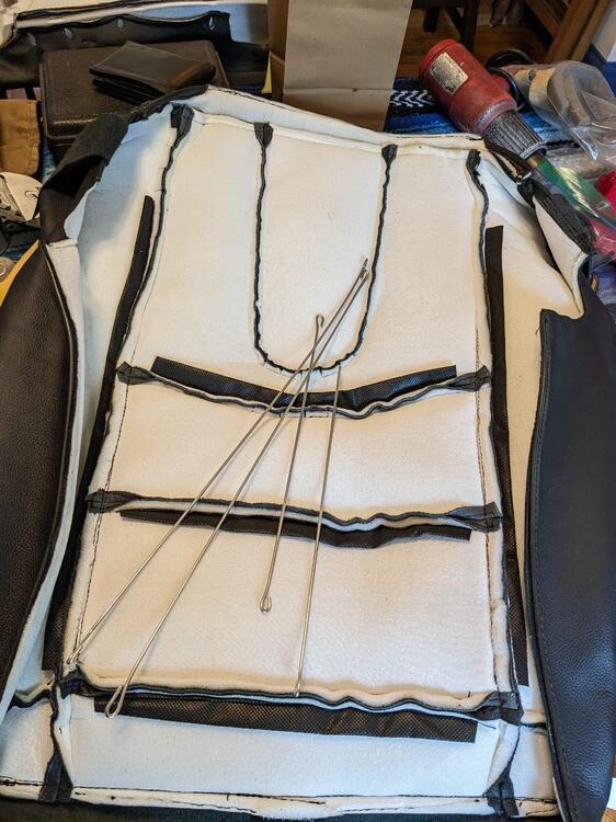
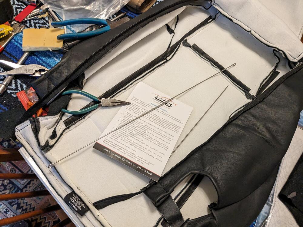
Thank you 😁 Unfortunately all the coat hangers these days are a thin gauge wire - I do indeed have plenty of those white coated ones, but they bend too easily for this. I used Stainless rod so I won't get rust should the seats get damp DTR
-
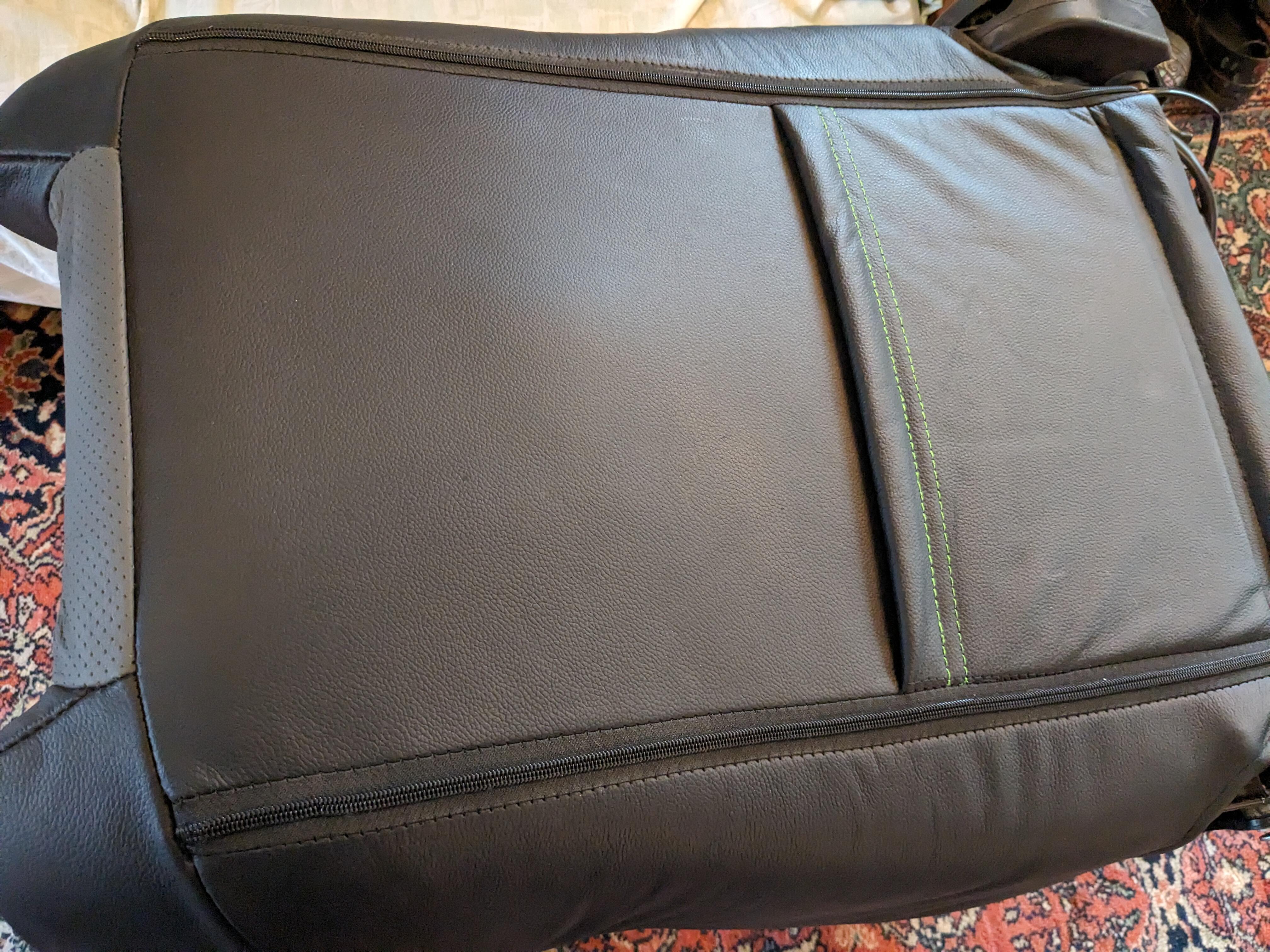
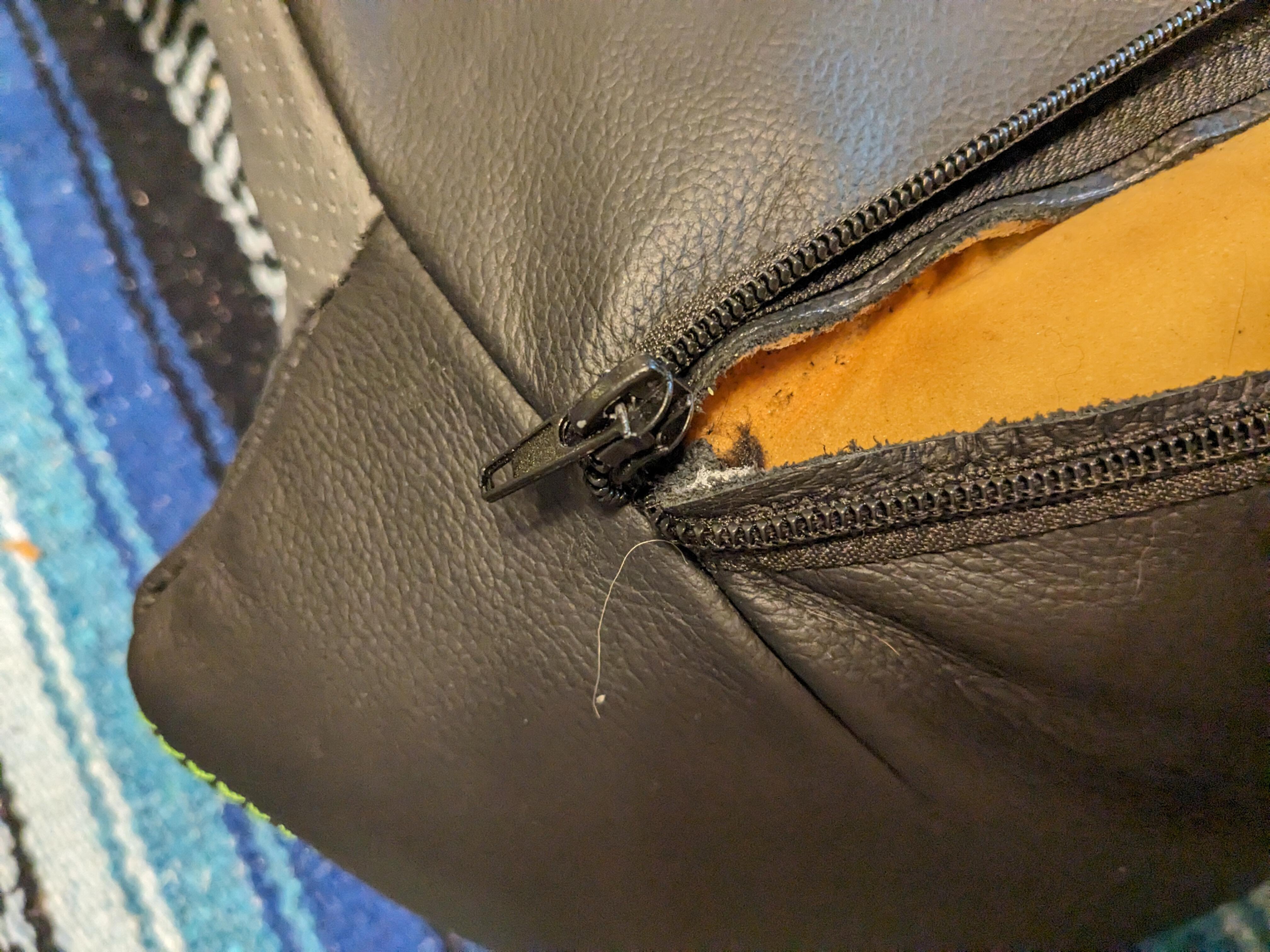
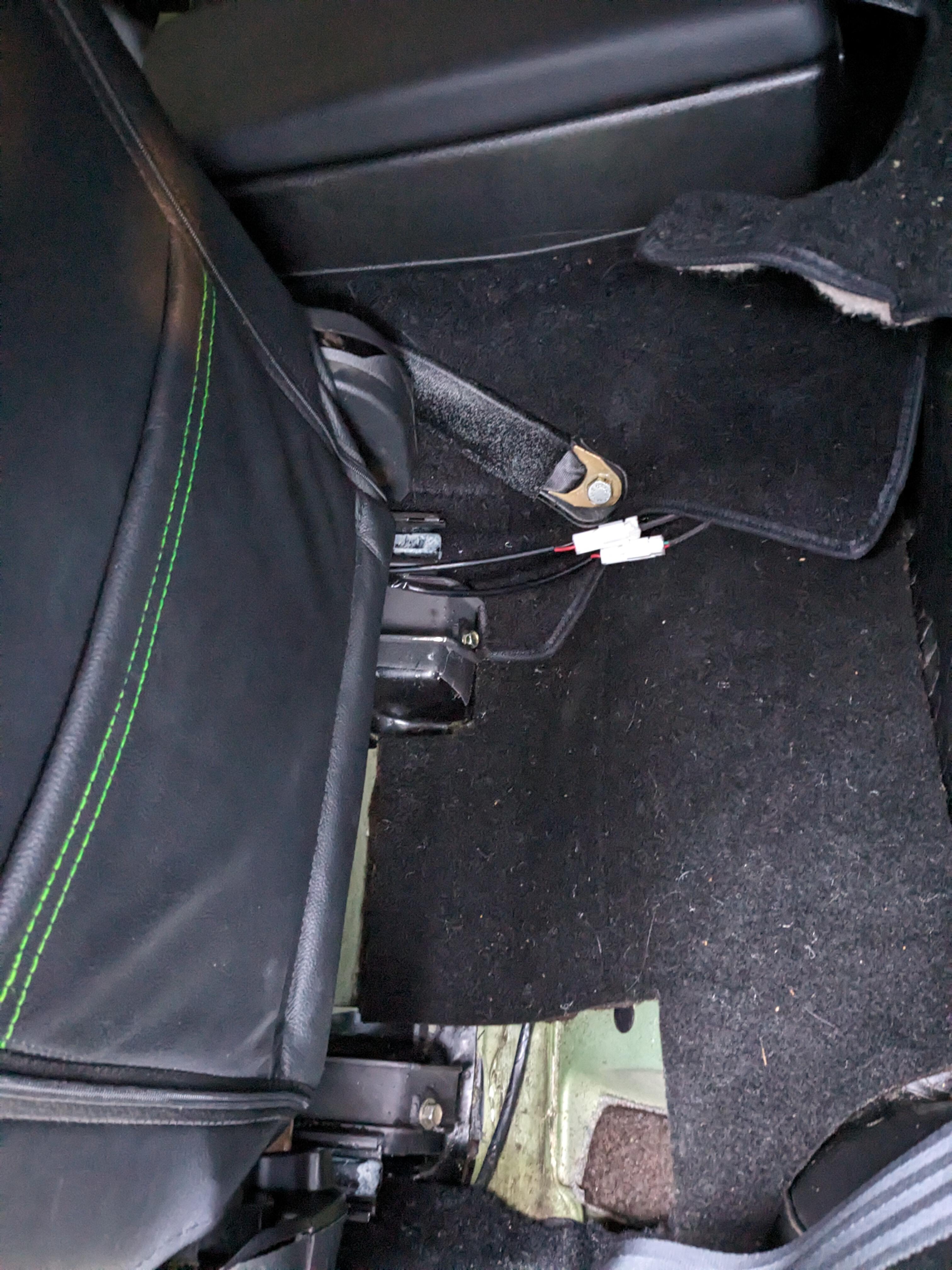
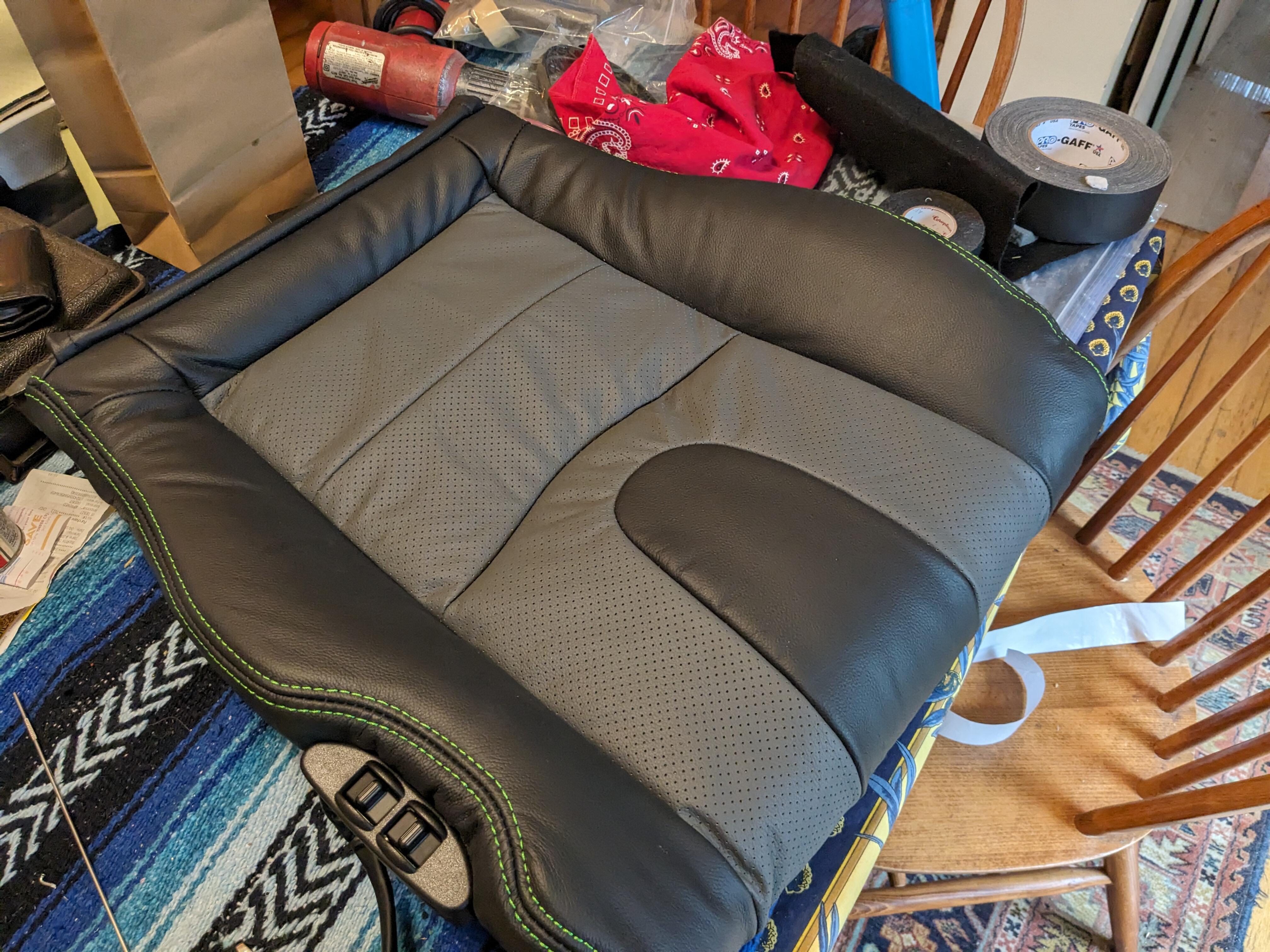
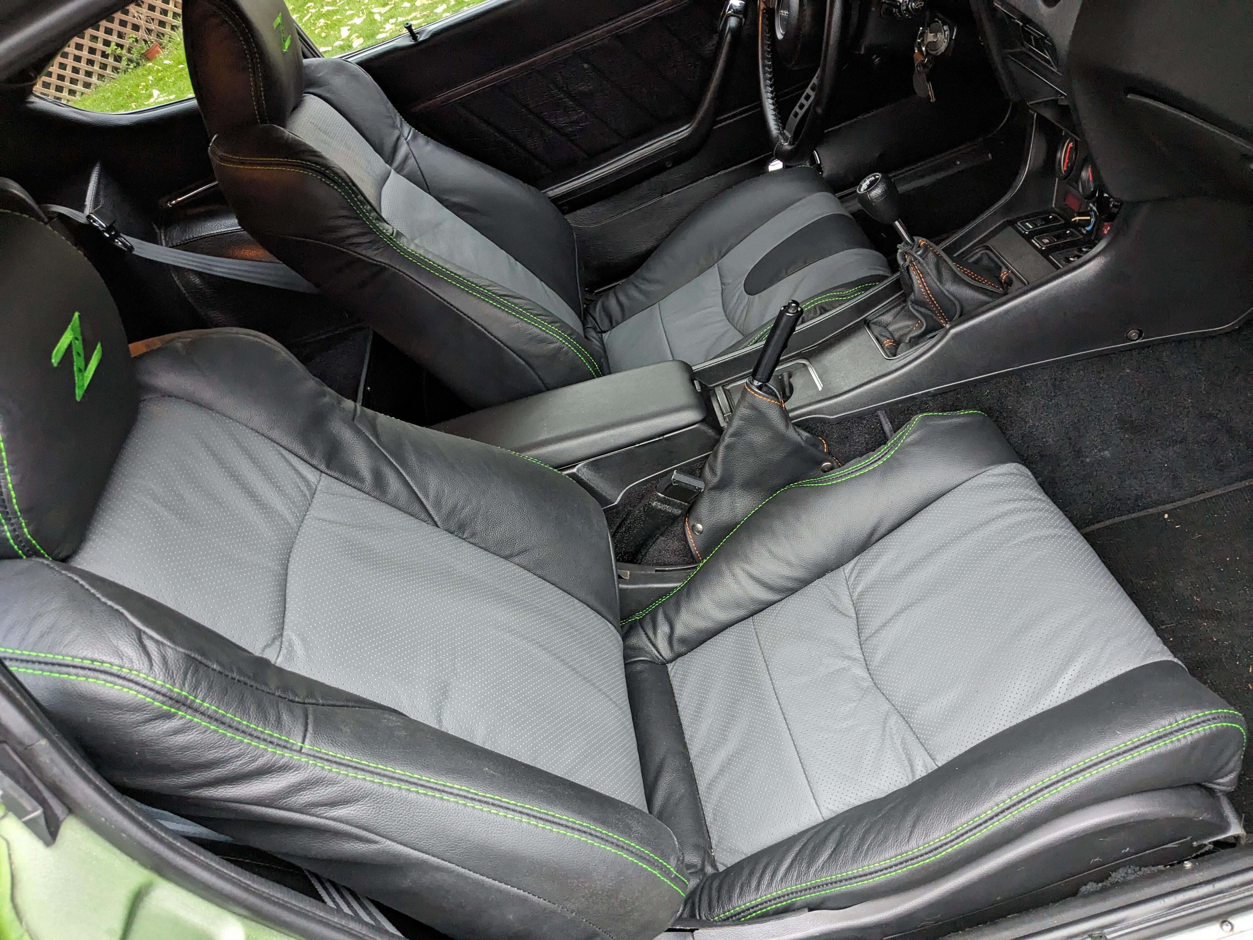
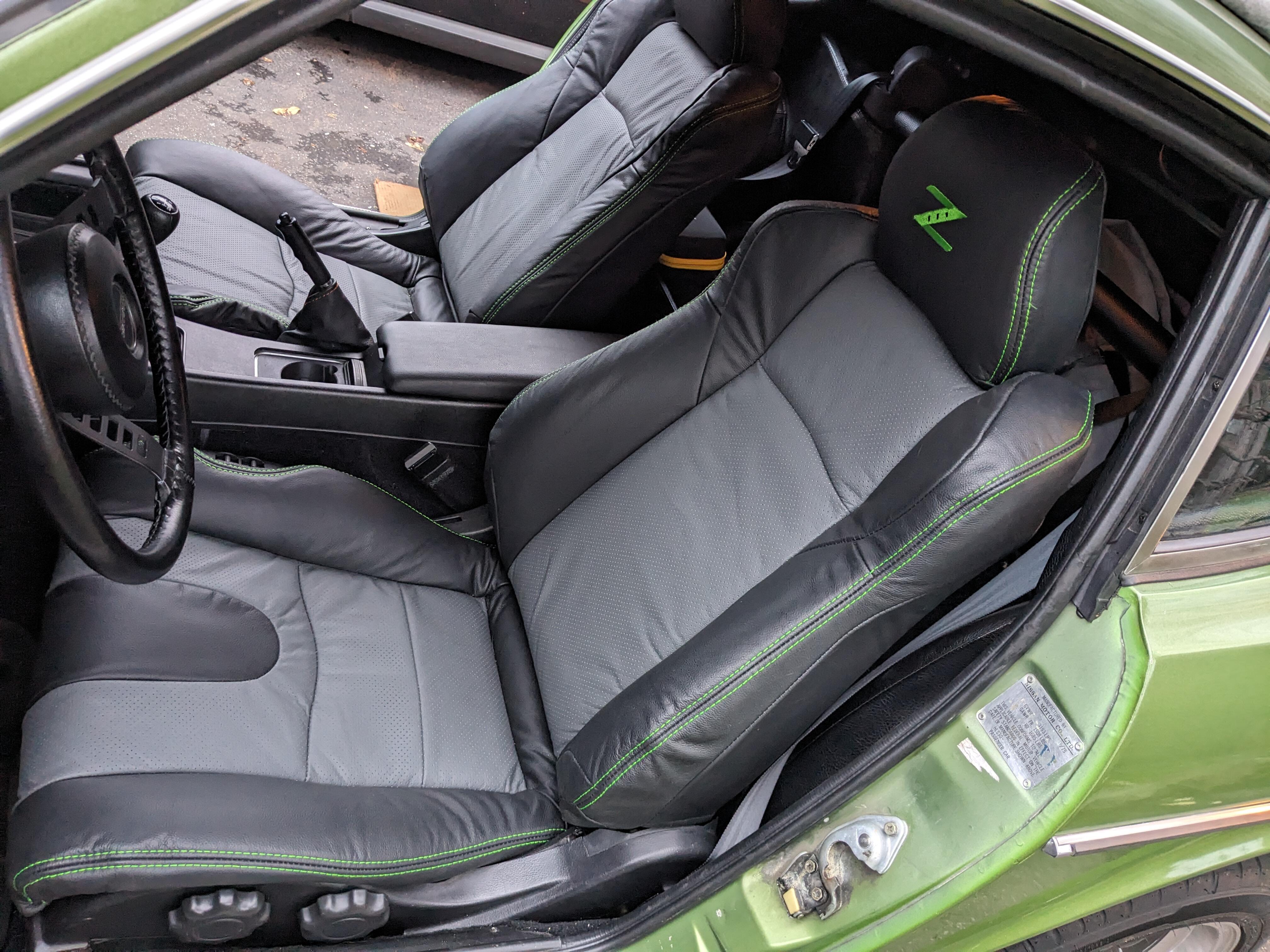
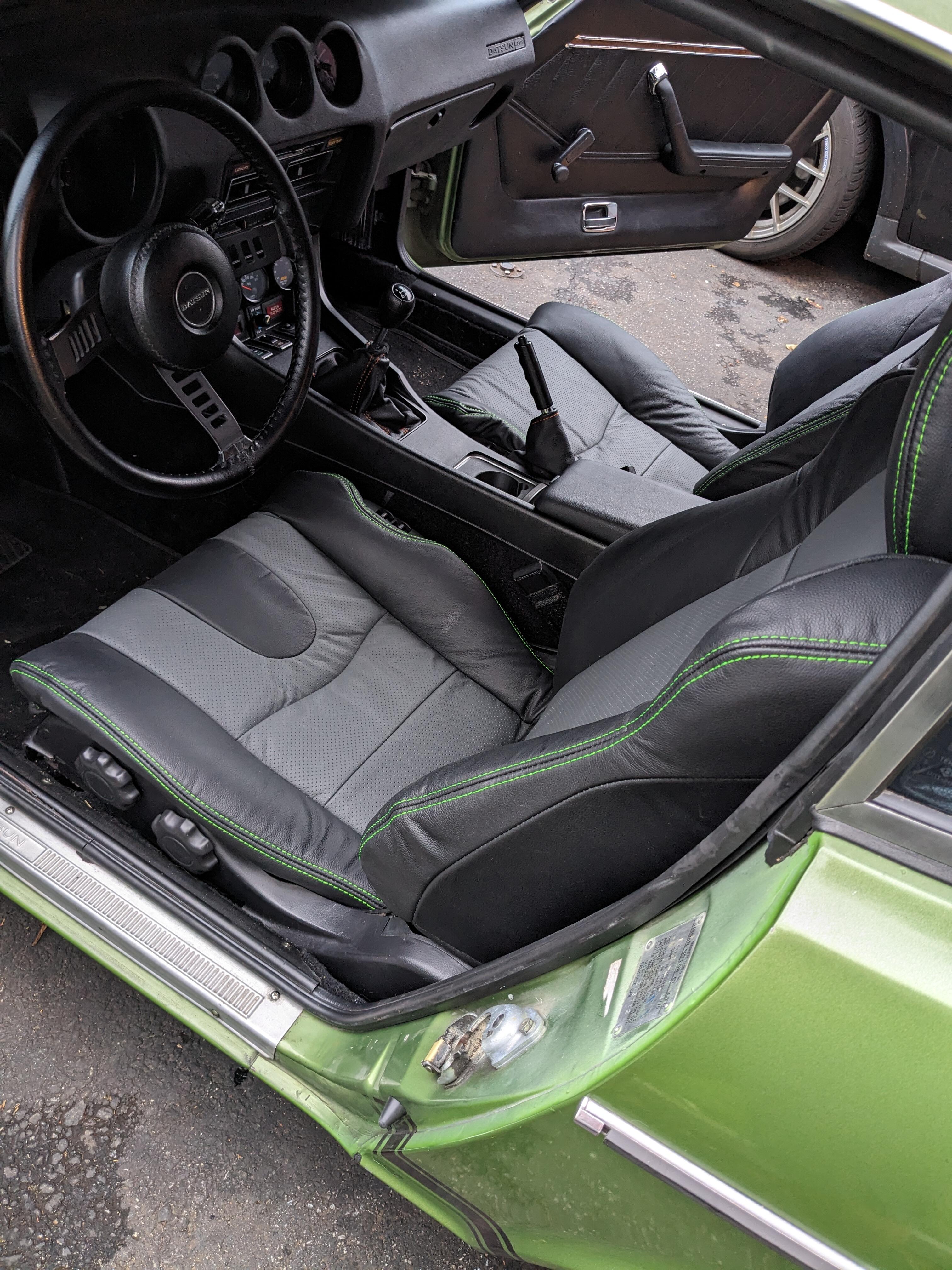
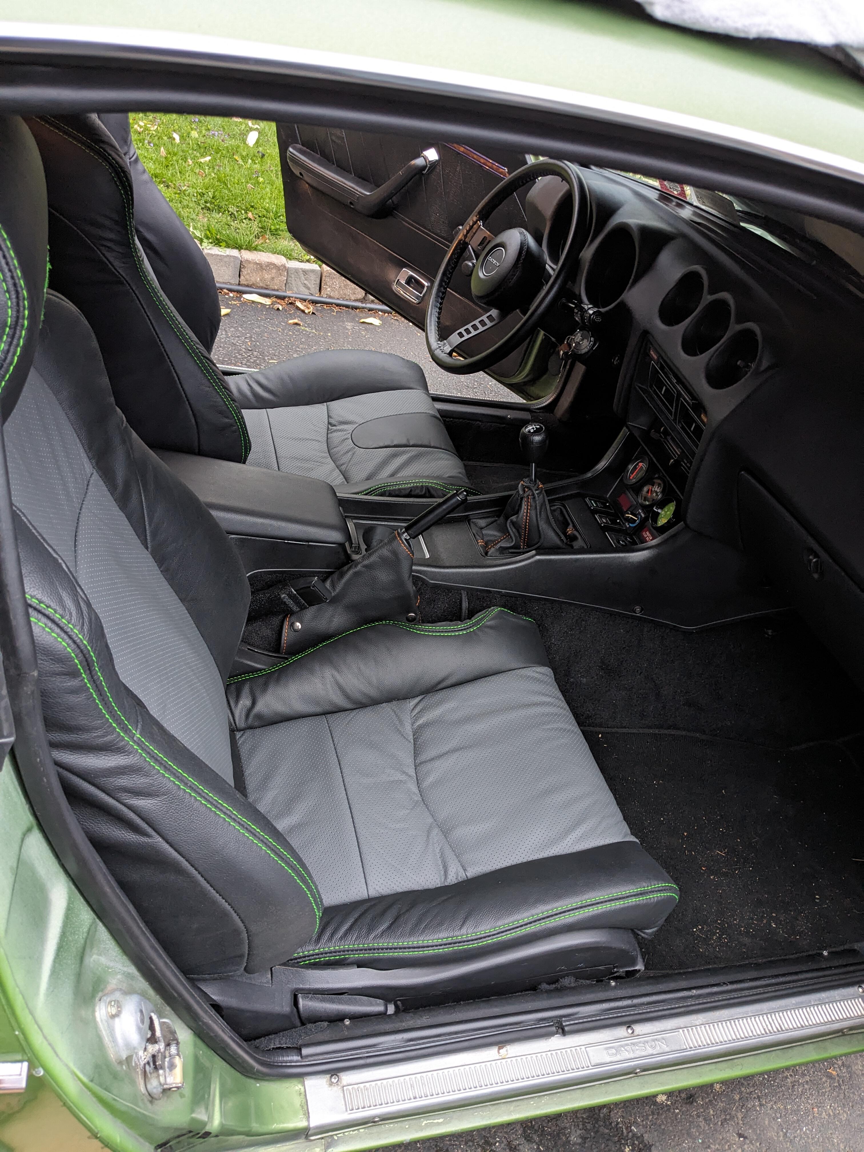
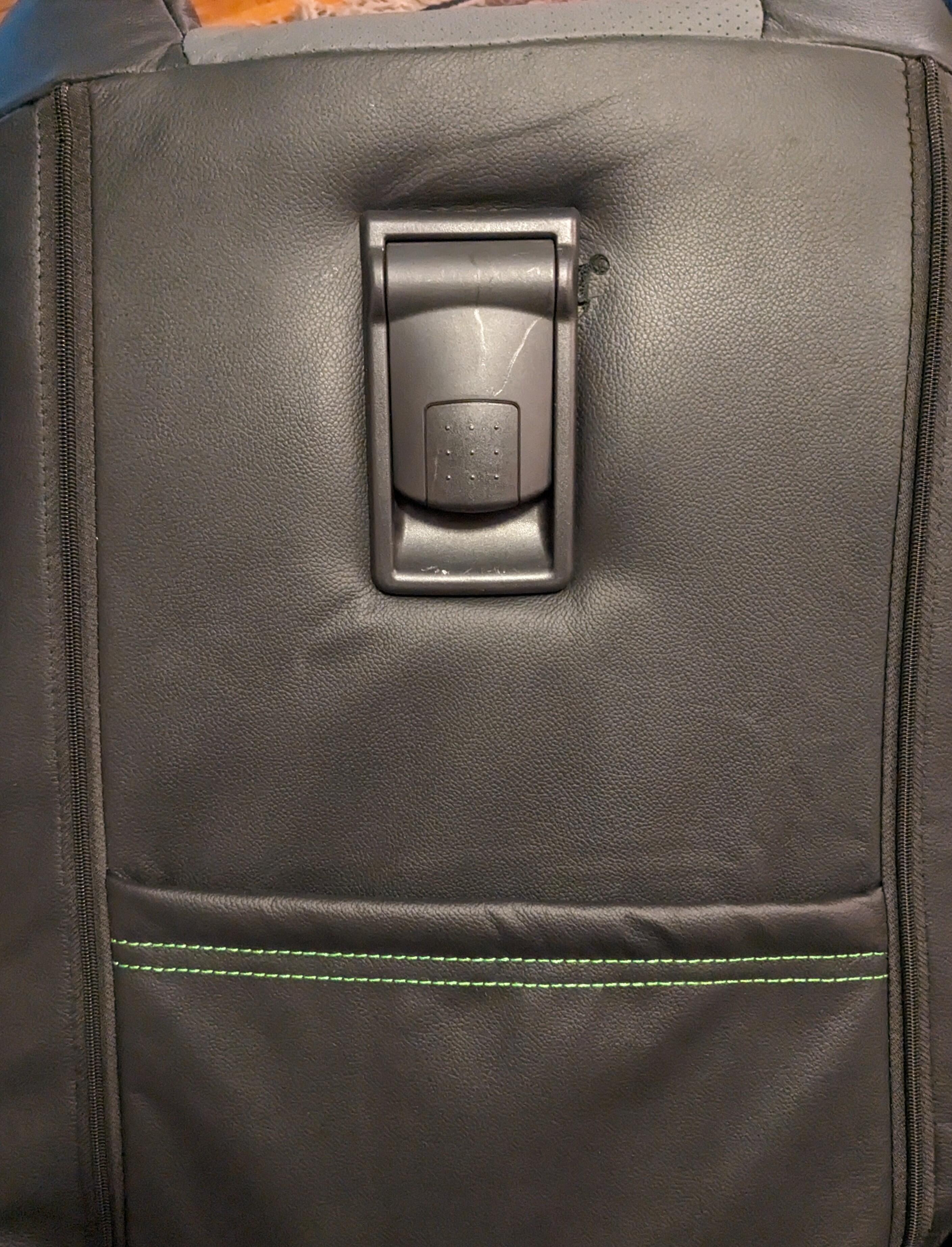
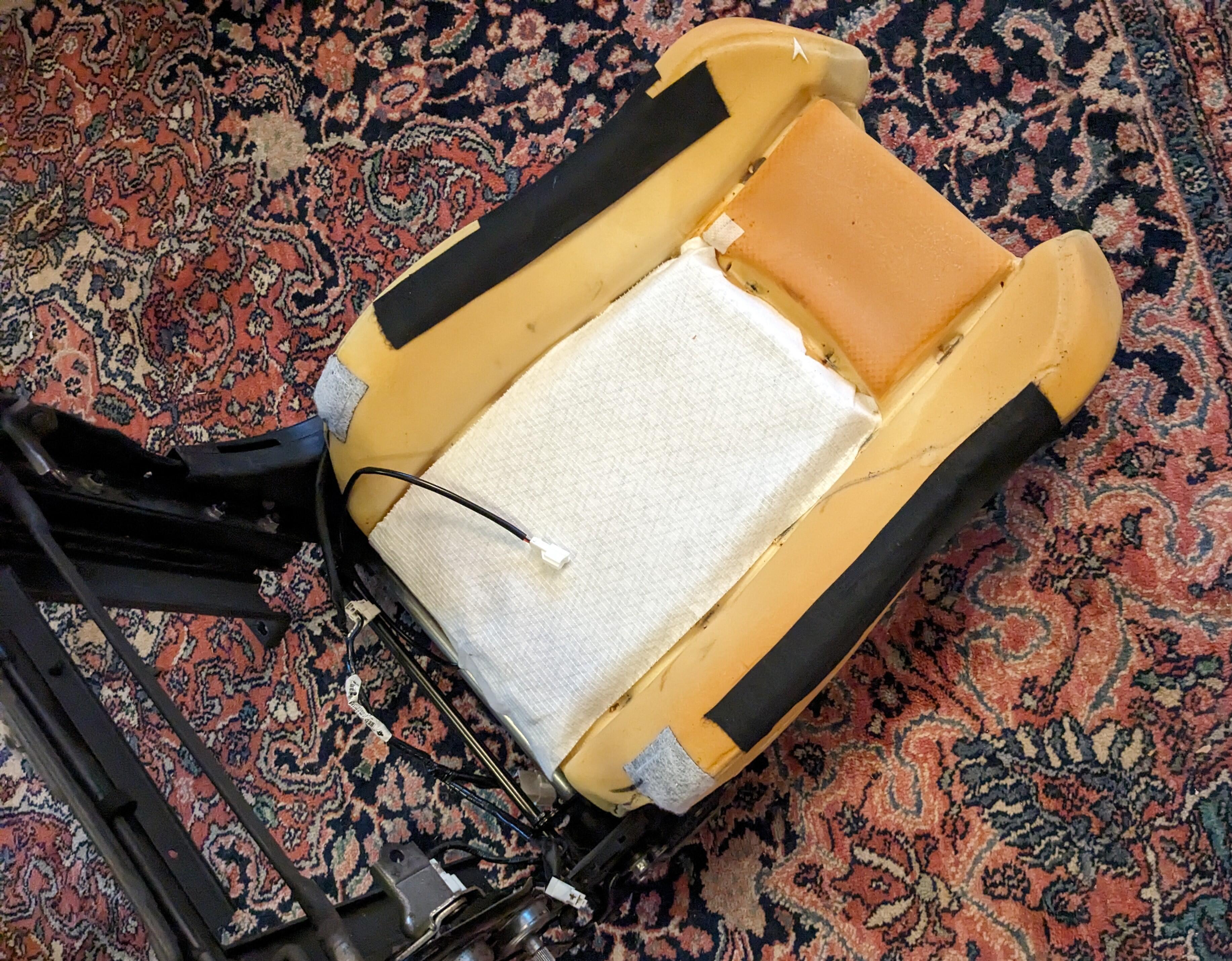
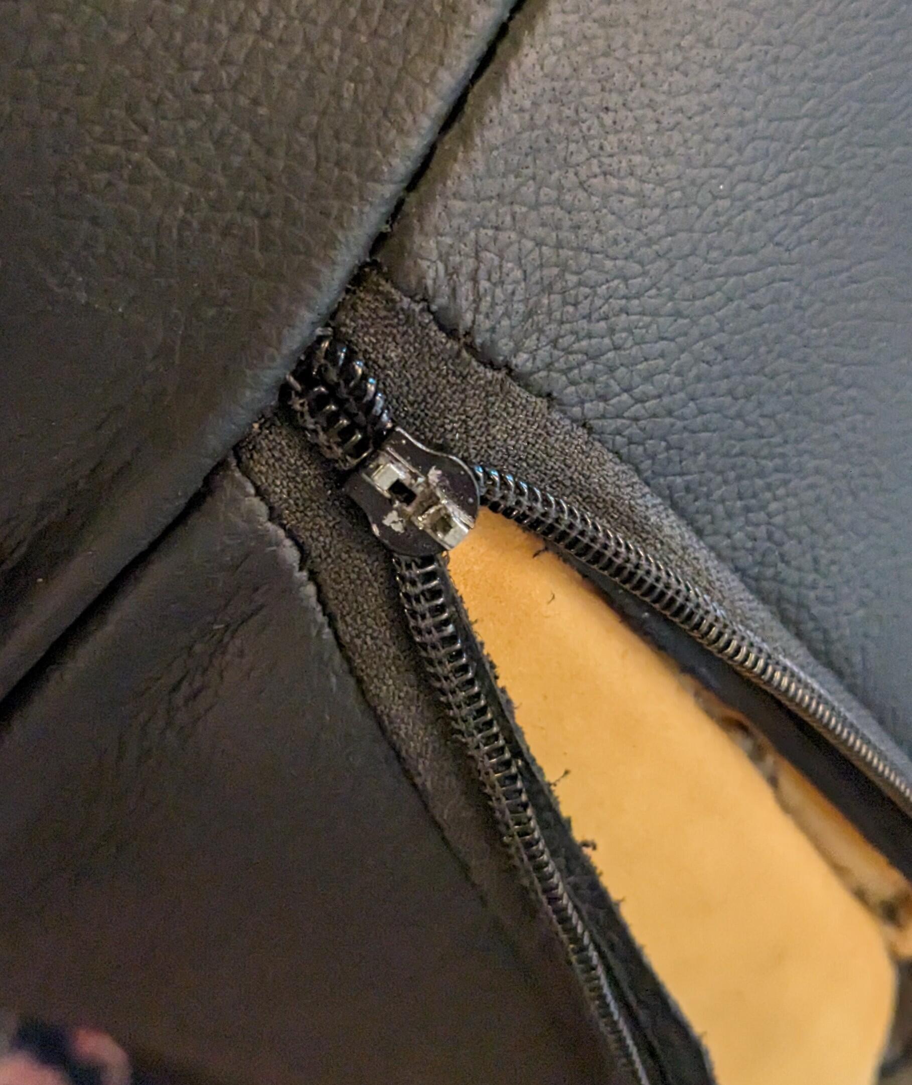
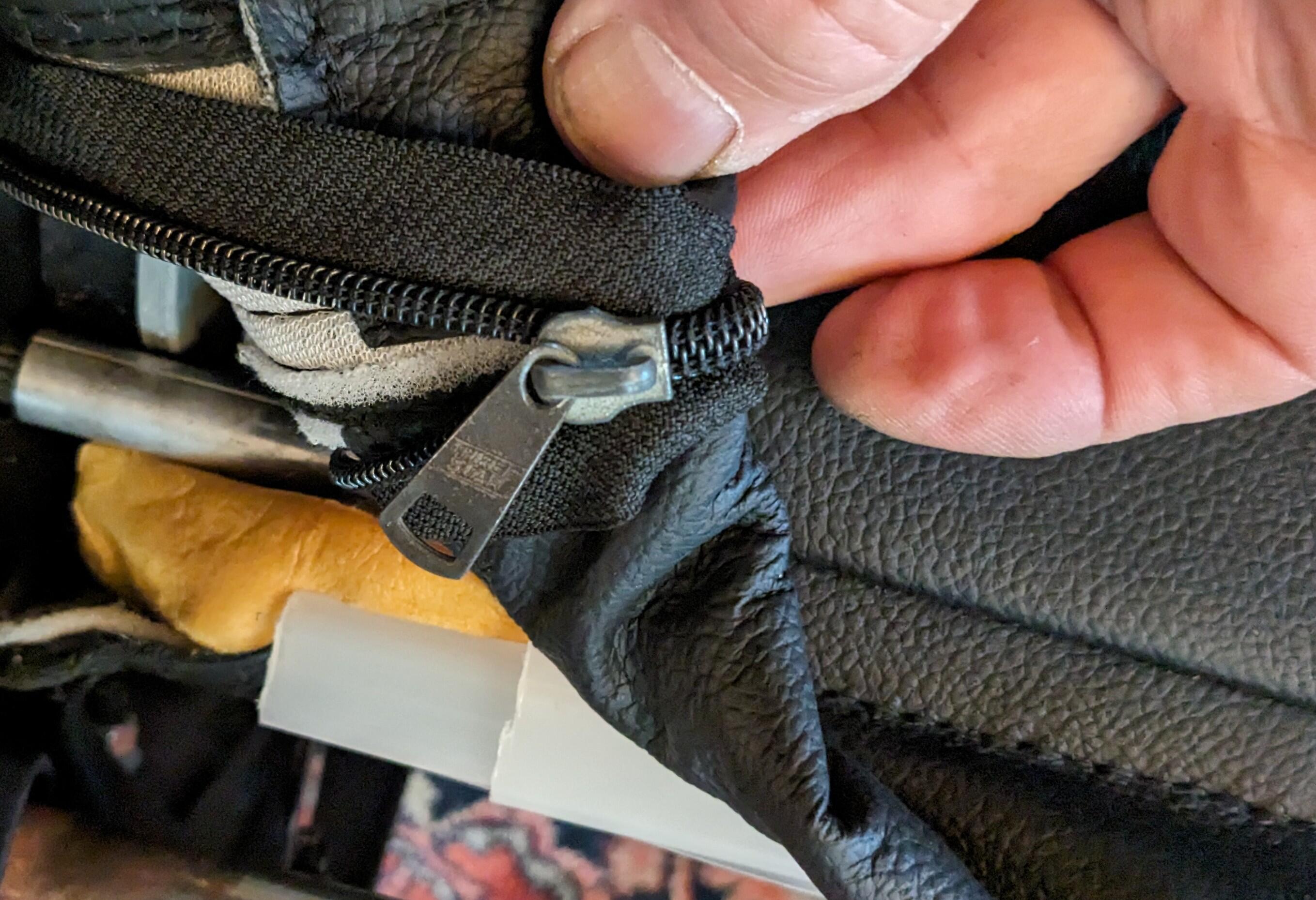
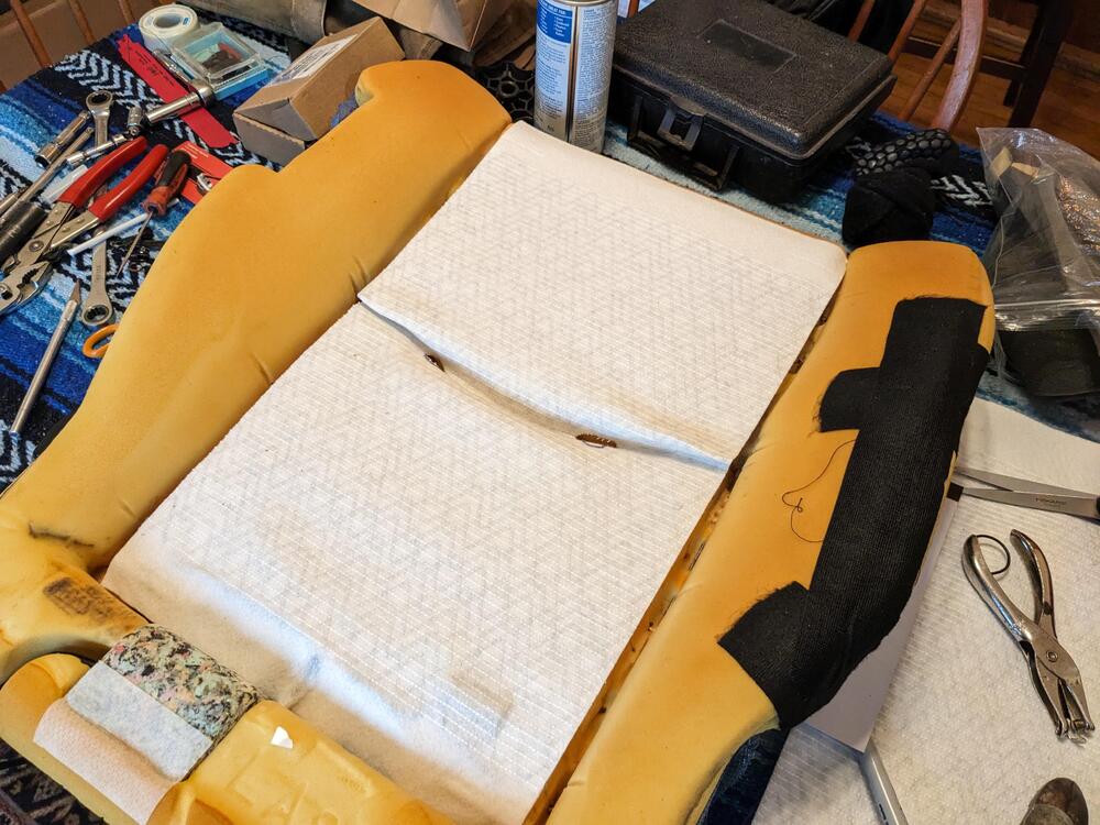
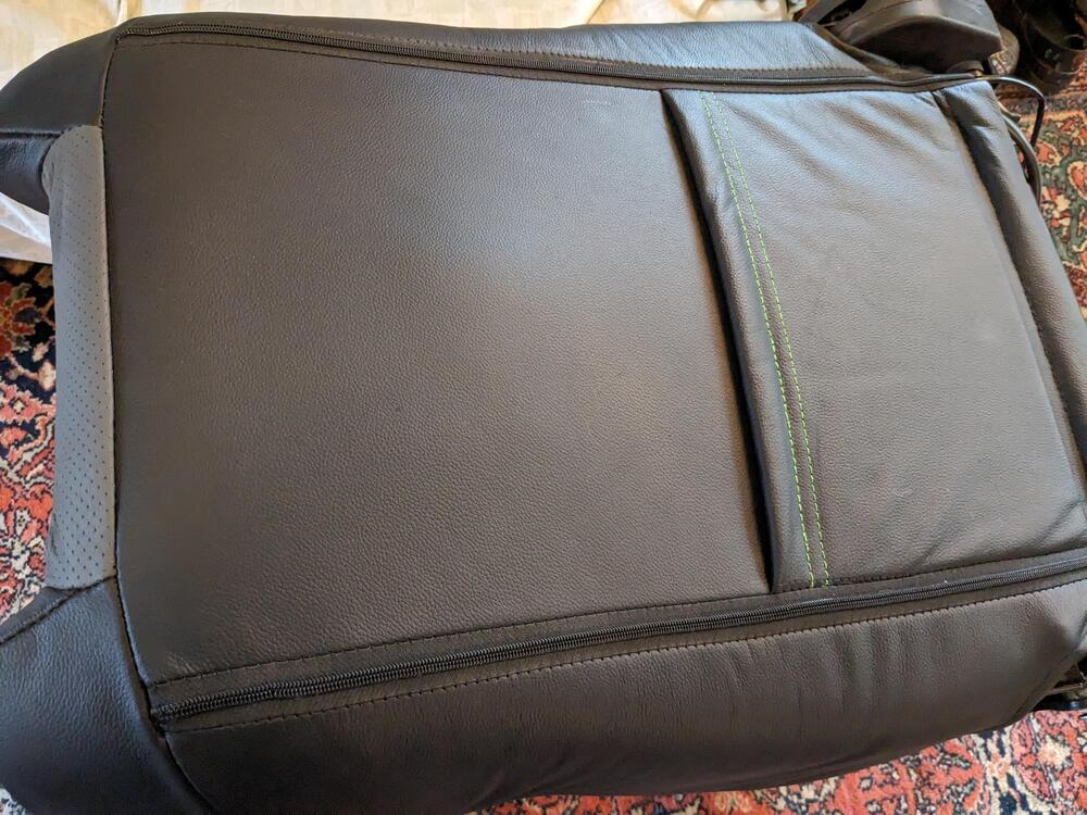
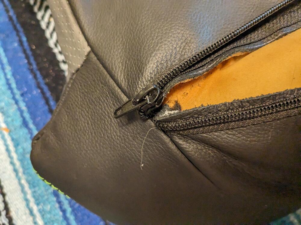
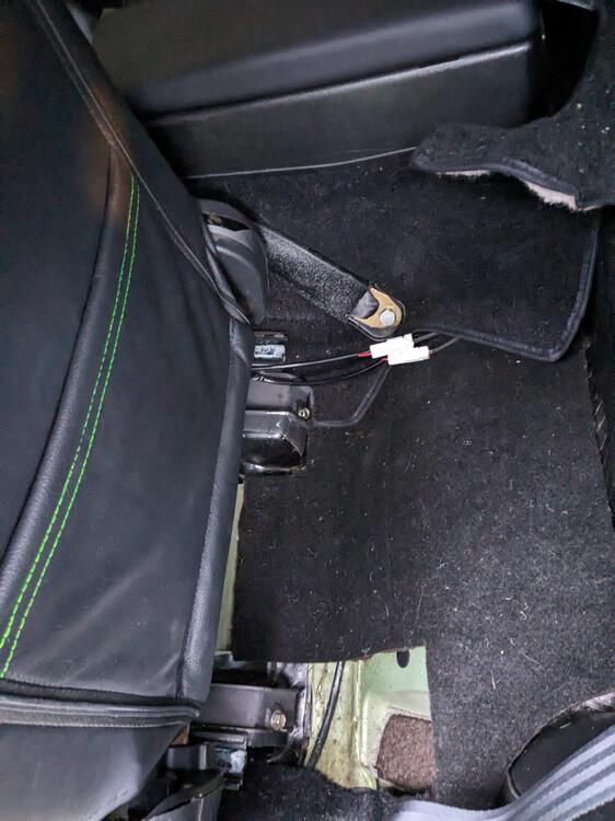
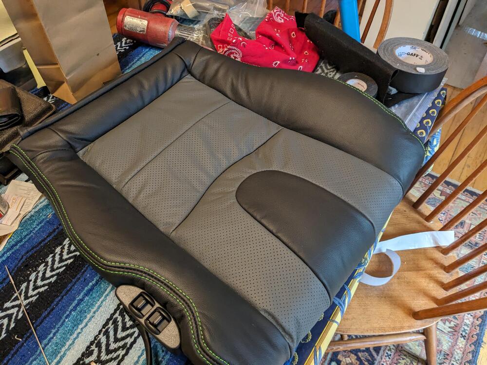
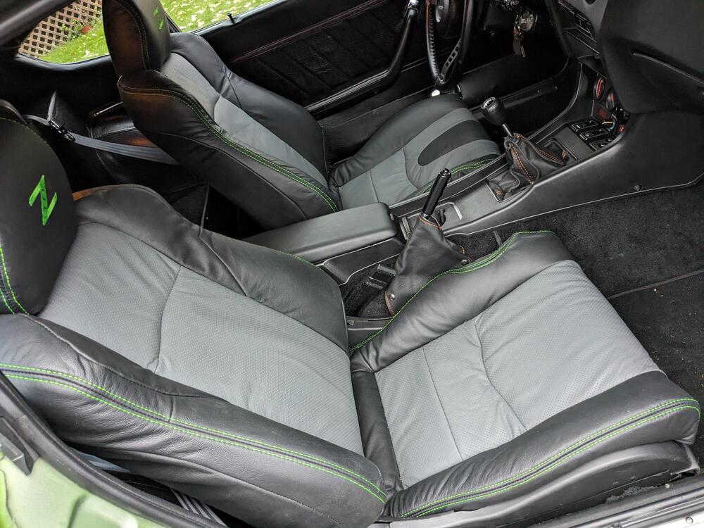
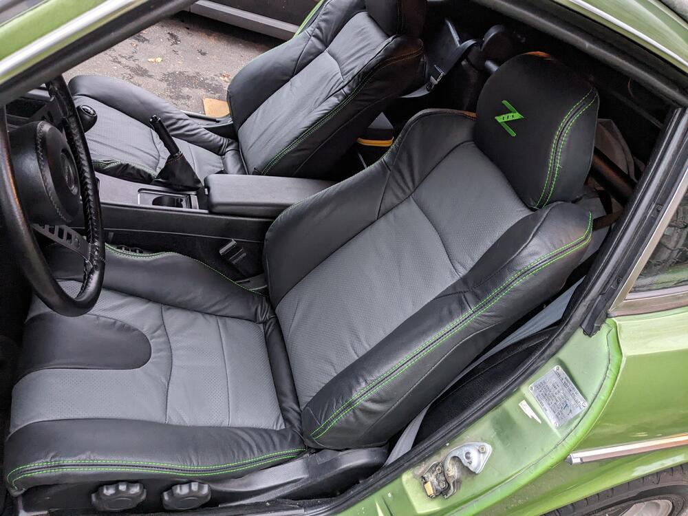
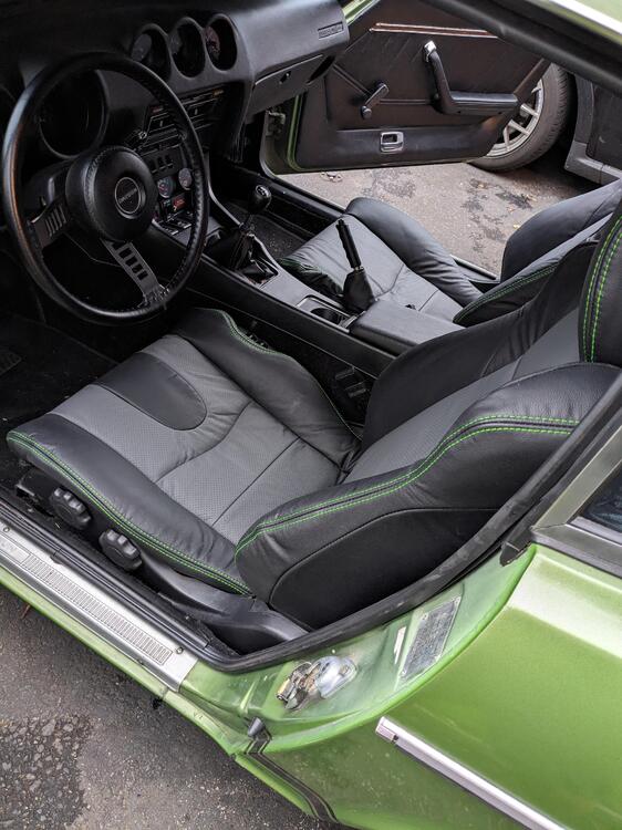
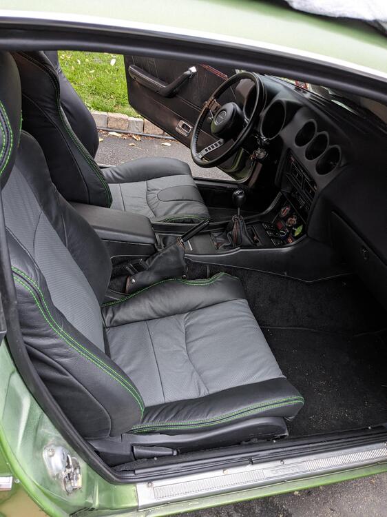
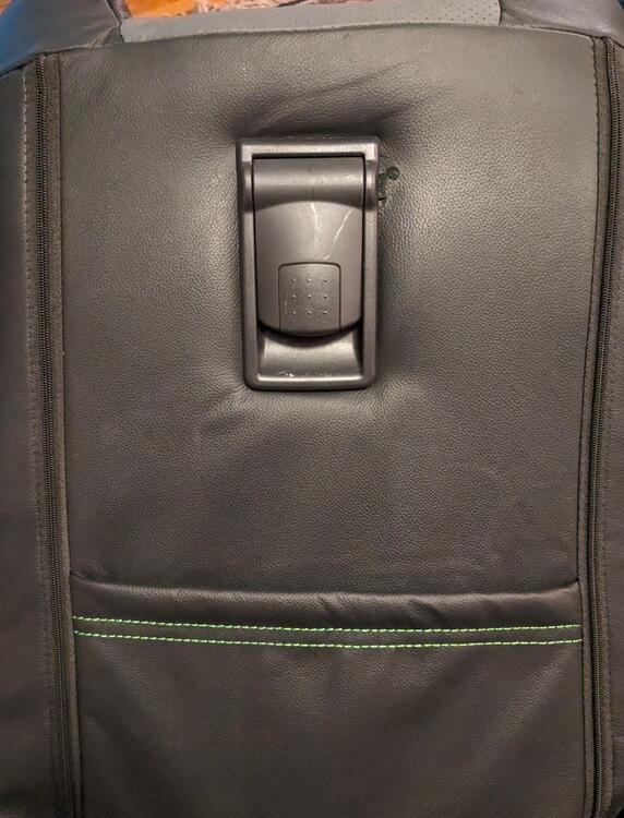
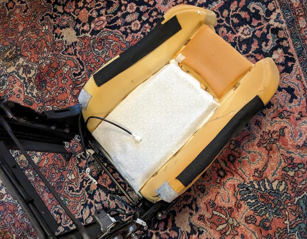
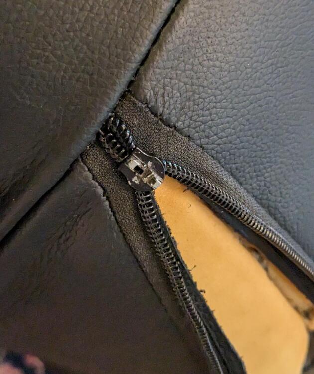
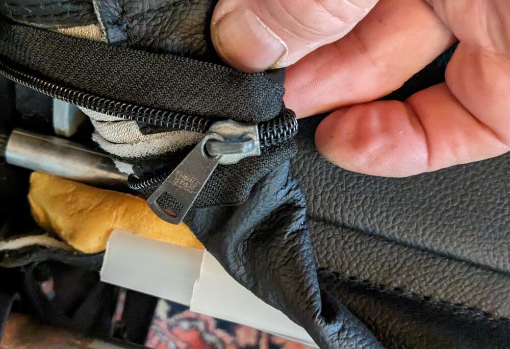
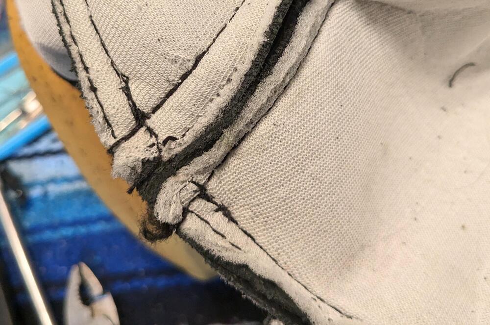
Did the upholstery today - I was off work, and just as well because it ended up taking most of the day to do it. One of the zippers was broken. I tried first to fix what was there, along with resewing the seam, that didn't work. So I had to take the seam part again, and replace the damaged pull/zipper with a better quality one. That ended up taking a couple hours. No word back from Ridies.com on the missing hardware or the broken zipper. Covers also didn't come with the required wire rods for attachment, so I made them using $$ welding rod Added aftermarket seat heaters that match the wiring I've already installed. The factory 350Z seat heaters are sewn to the upholstery. No practical way to transfer that, and it would have had to rewire the car to make it work anyway. Damaged zipper After first repair, pull tab also snapped off All zipped up Sewed over the zipper end so it can't open up on the backside of the pull Stronger pull Drivers seat cushion One self inflicted wound - I miscut the opening for the back release 🥺 Back in car. Plugged the seat heaters, but forgot to test them
-
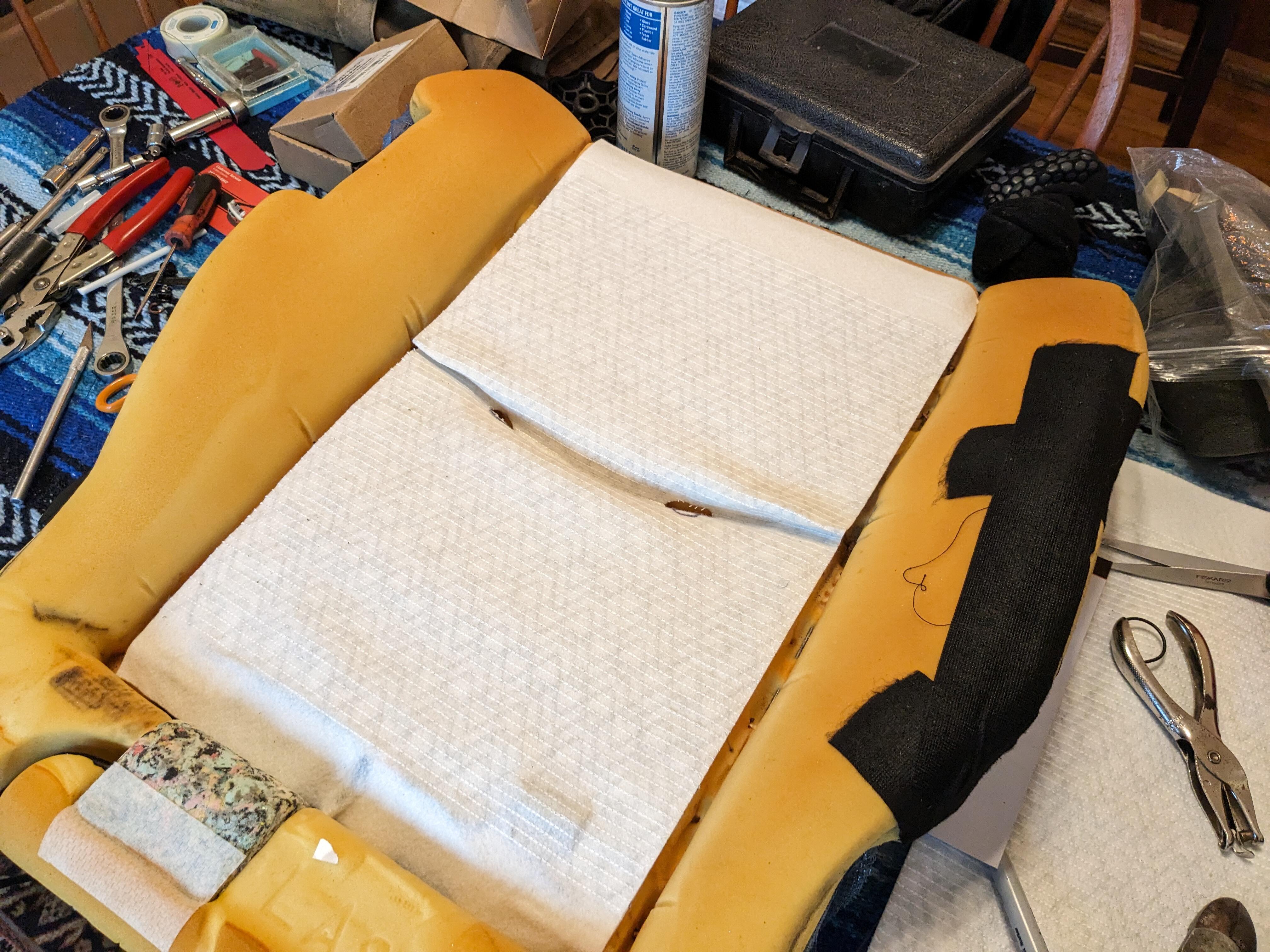
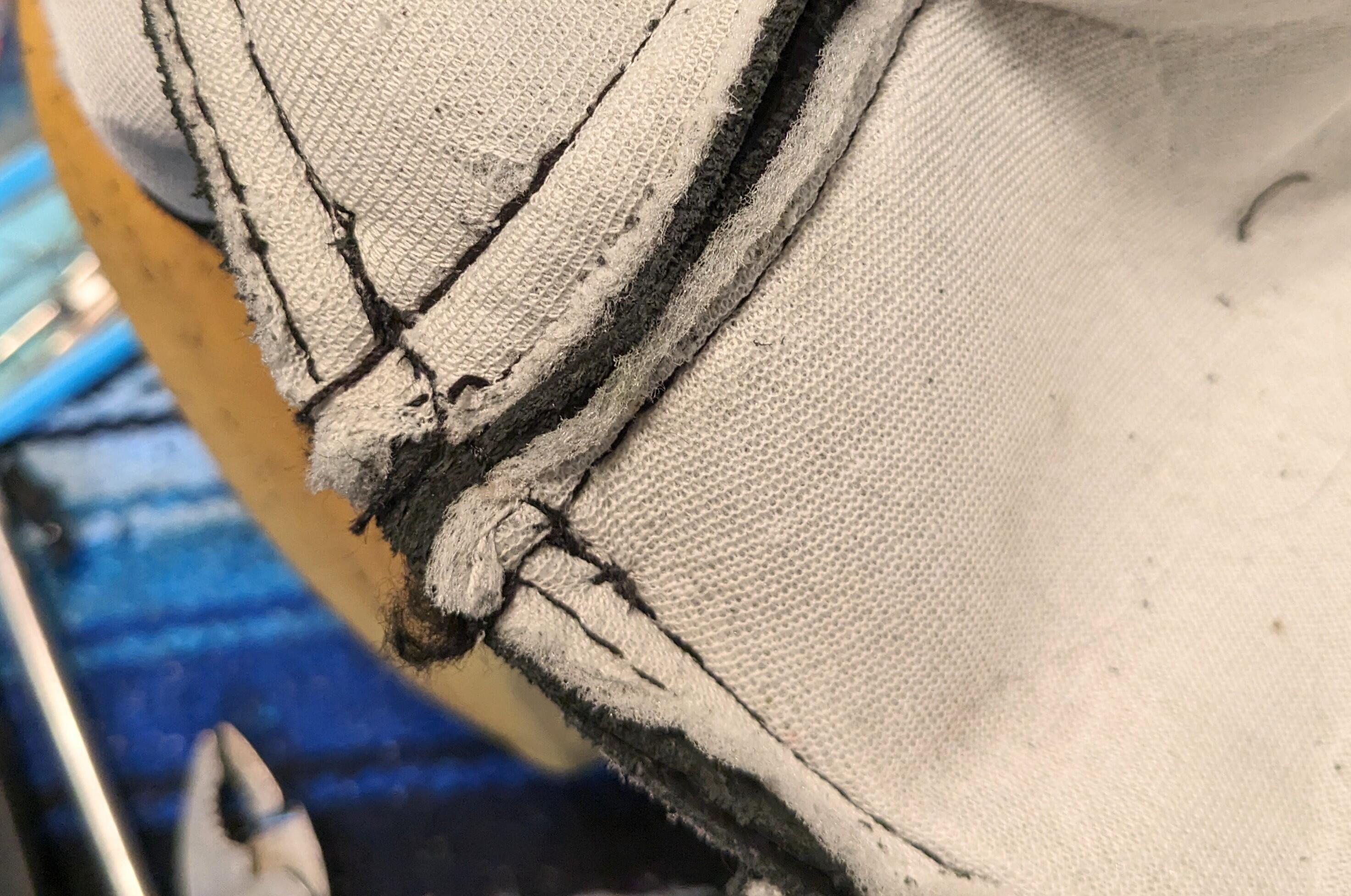
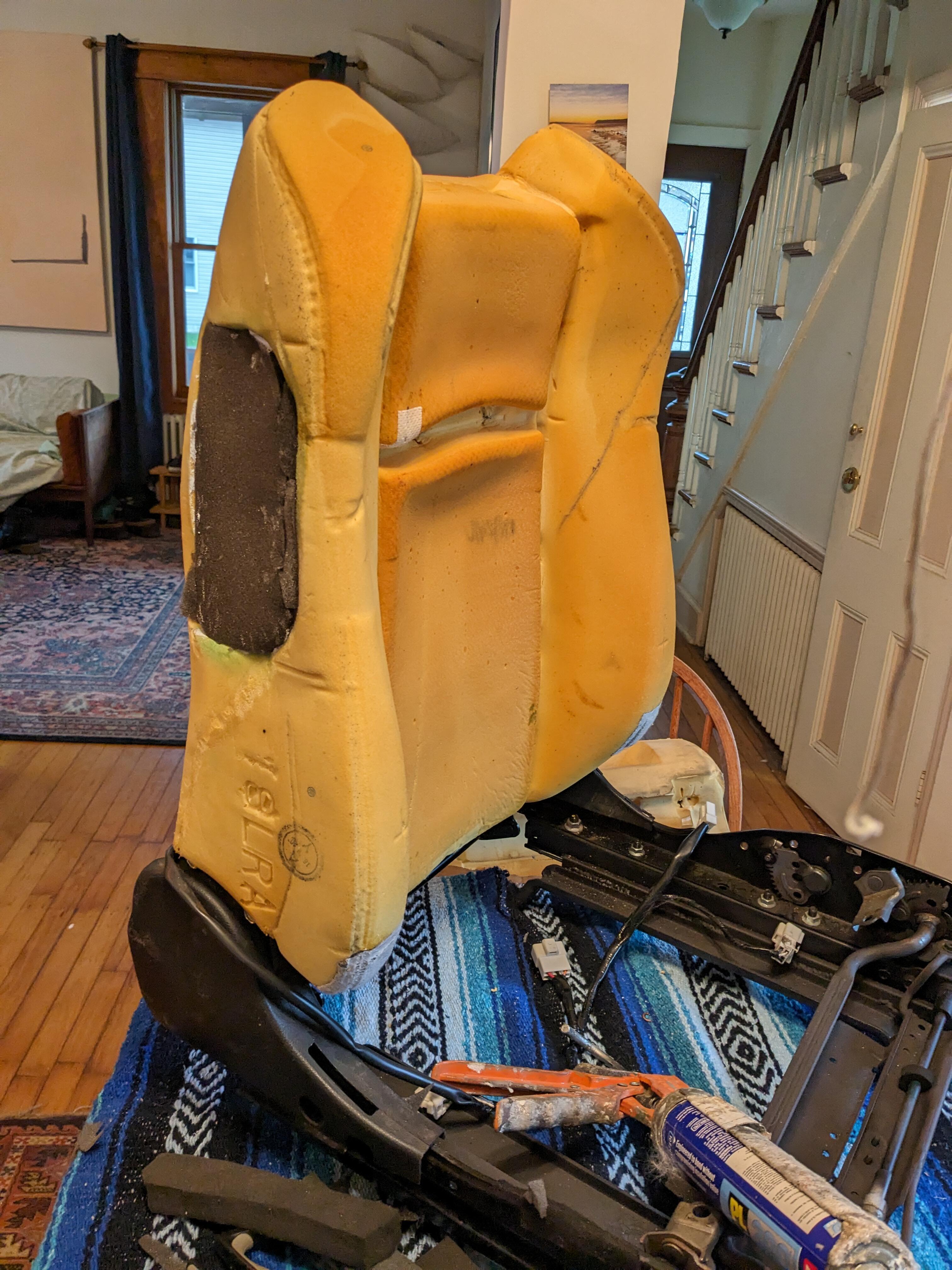
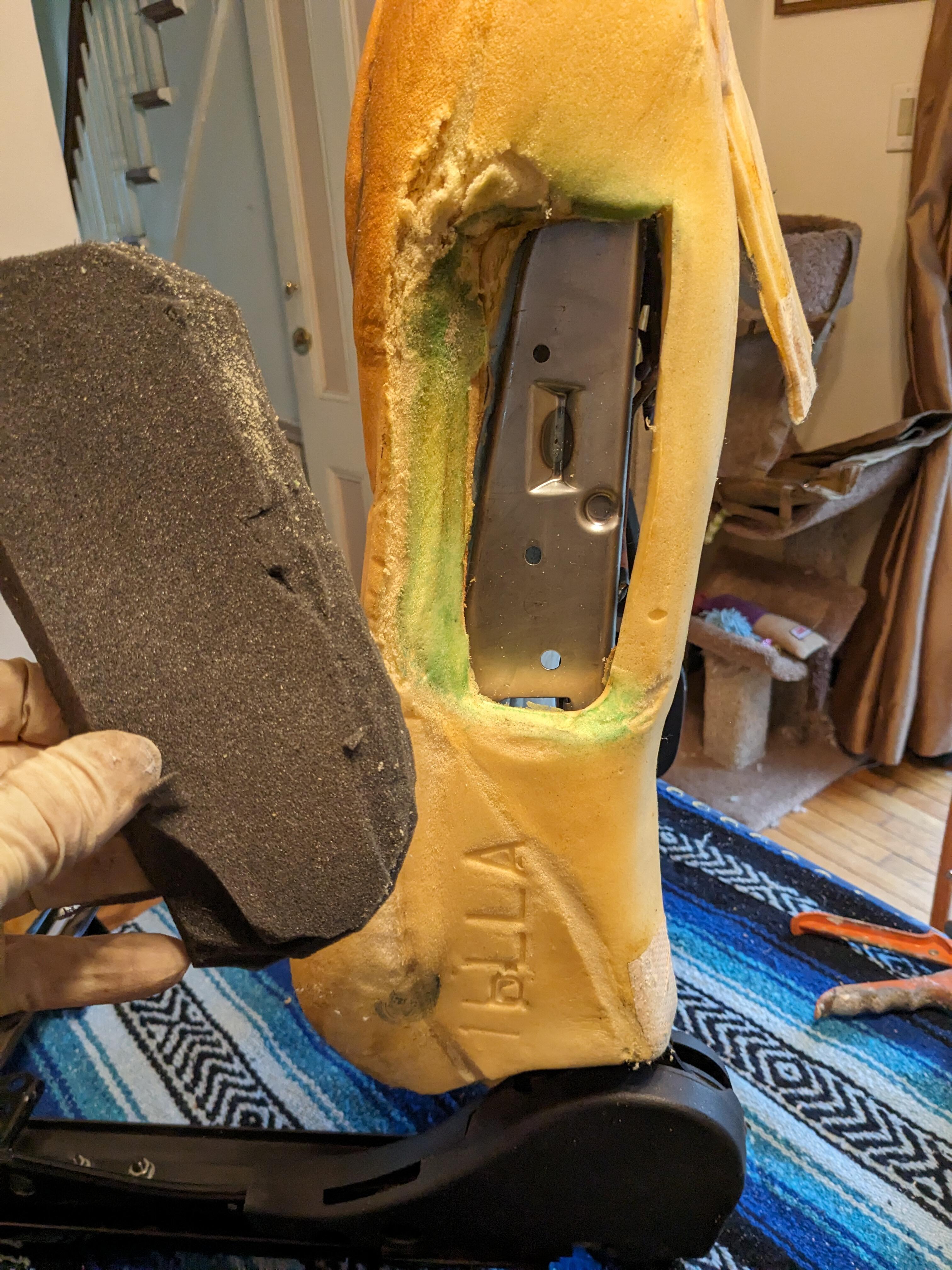
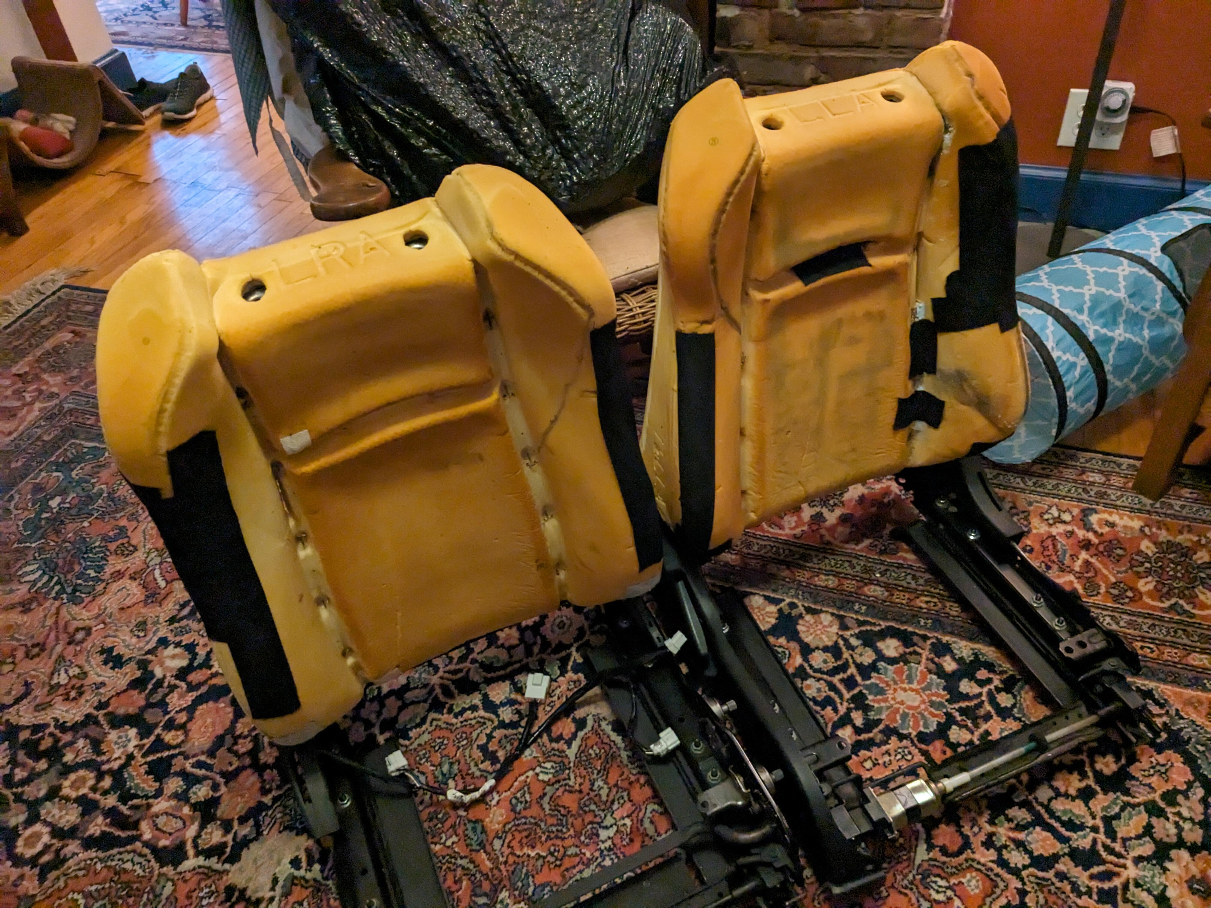
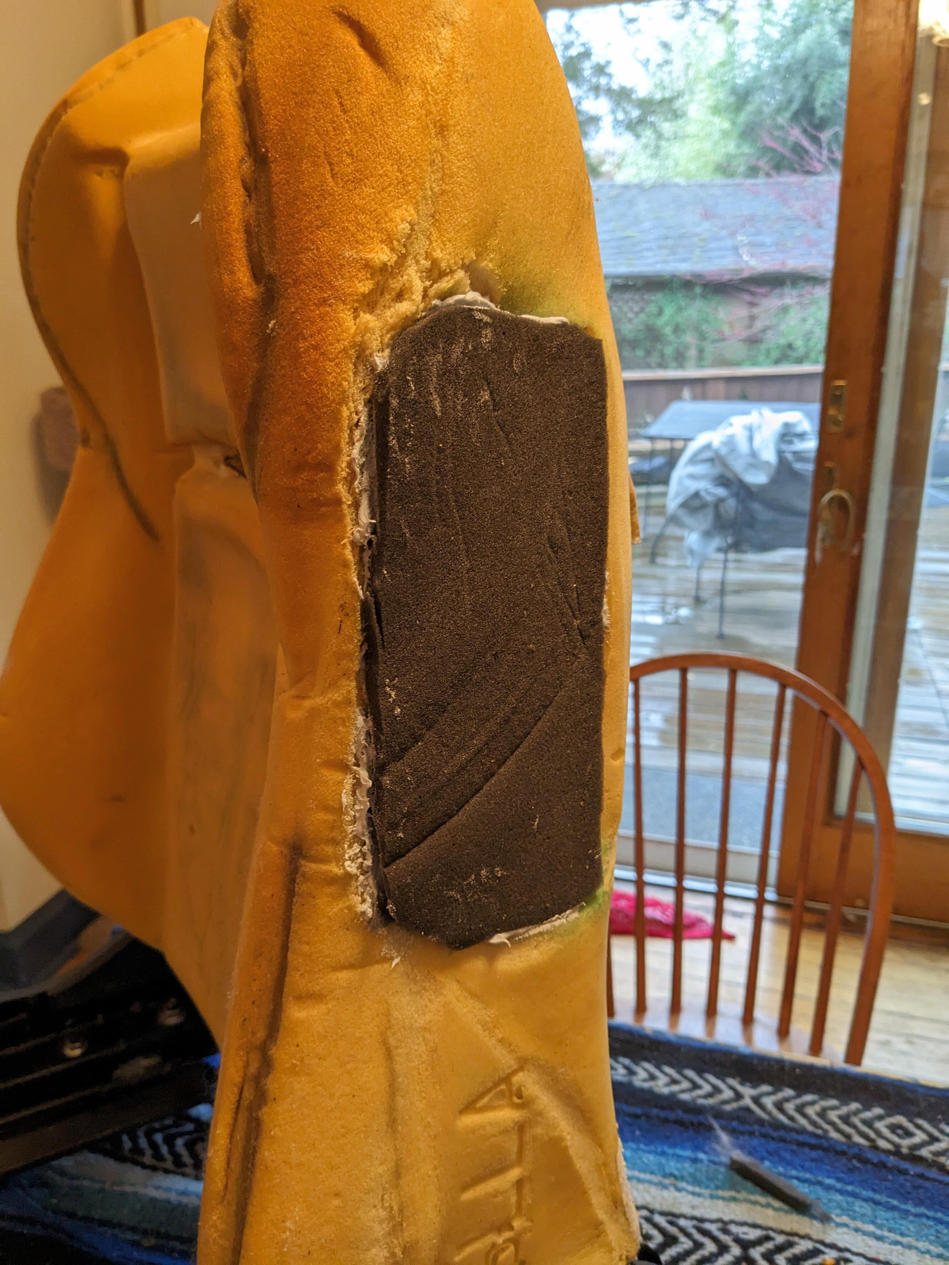
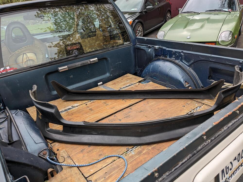
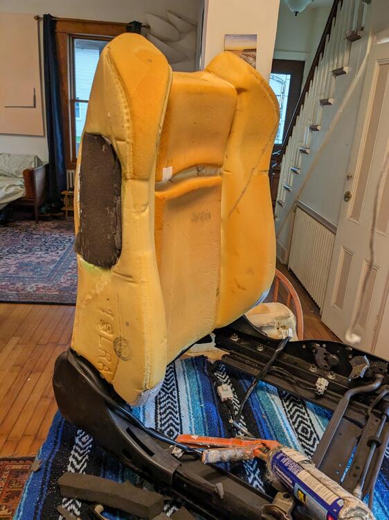
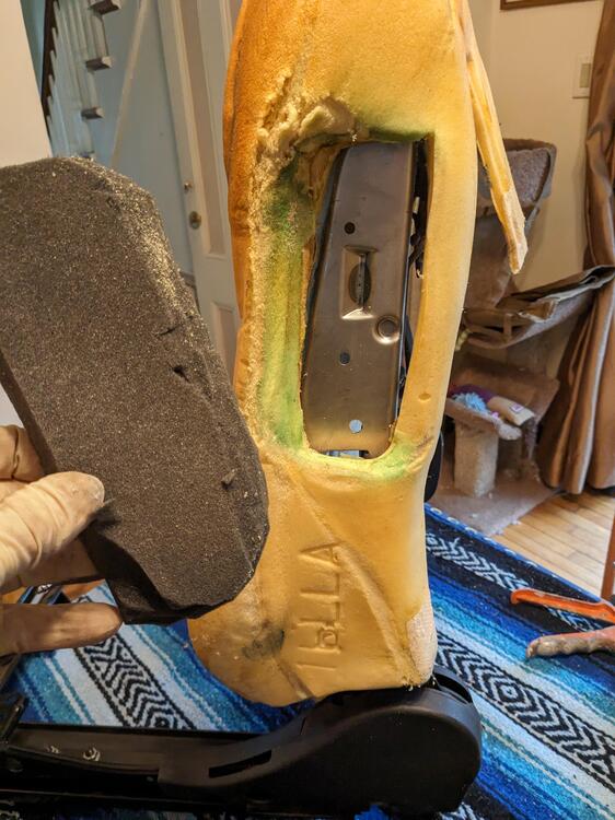
Took the front spoiler off after work & got it to the body shop for paint next week. Also got the front seats out just as the rain began - it's supposed to rain through tomorrow, so I figured a good time to get the upholstery done. Removed the upholstery & made a filler piece for the side airbag location. I'm also switching the cushions left to right, as the outside of the drivers one has more wear. The PO was on the heavy side and it shows in the compression and tears in the foam. Switching them means that the worn sides will be on the inside of either seat, so not likely to be an issue down the road. Had to cut a slot for the rear seat release on the passenger side. If I could get hold of the rights quick release I would put another on the driver's side since that has electric it's a lot slower to rake than the quick flip lever Dense foam was a large pad used as packing for my LUK RS clutch & DM flywheel kit, I really don't throw much out
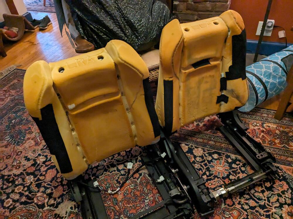
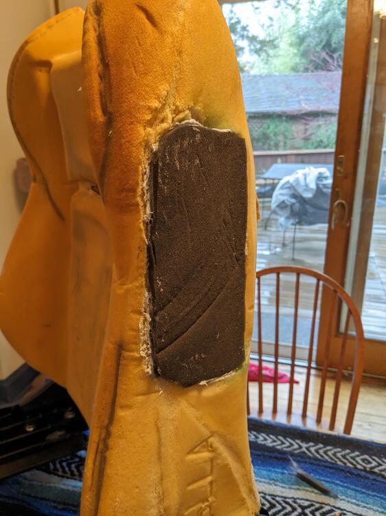
-
I've been driving the Z to work pretty regularly (as long as no rain is forecast), and the car has not missed a beat since replacing the original relay. Many thanks again to Zed Head for his input - it would have been a bitch to find otherwise.
-
So, question - has anyone determined a suitable generic replacement for the earlier (75) style external return spring? I'm looking online & of course can buy a generic set off Amazon or from Harbor Freight, I just want to make sure I get something that will be a suitable weight. I cleaned mine up when I did the TB cleaning, but the tension isn't enough - I often find the throttle not closing properly during light throttle (low speed, in town) situations TIA
-
Thank you Pat. It would have been nice had it gone for more, however that does cover the cost of the 280Z and all the parts I have put into it so far, so that's not bad. The guy that ended up winning, actually lives about half an hour from me, so it's a good chance I'll be seeing the car on the regular basis. He did say he followed some of the builds I had done on the Fiat forum X-Web, although I don't think he ever signed in. He does actually have 2 X1/9s already. I don't think the guy has any in depth ability to work on them himself.
-
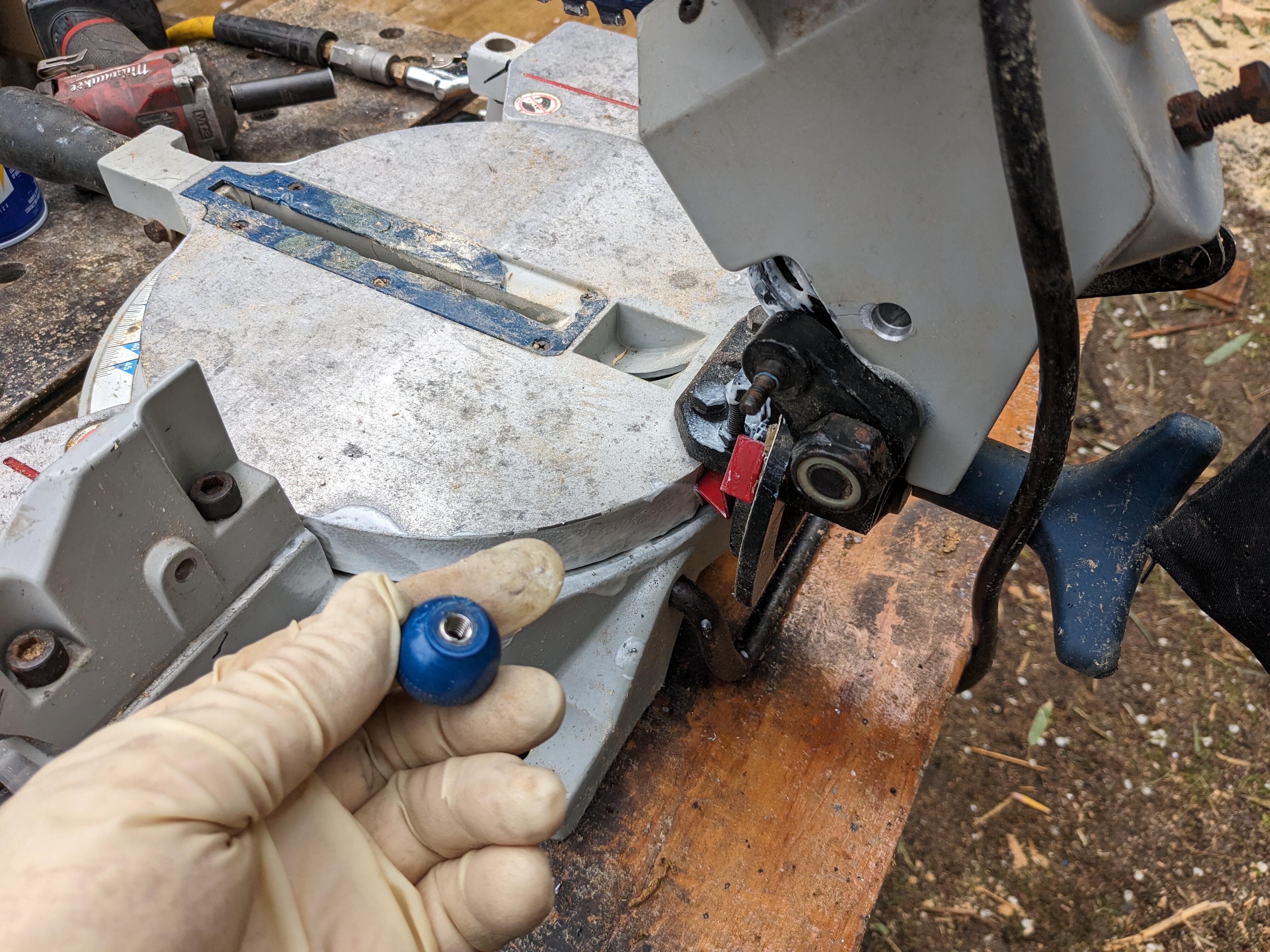
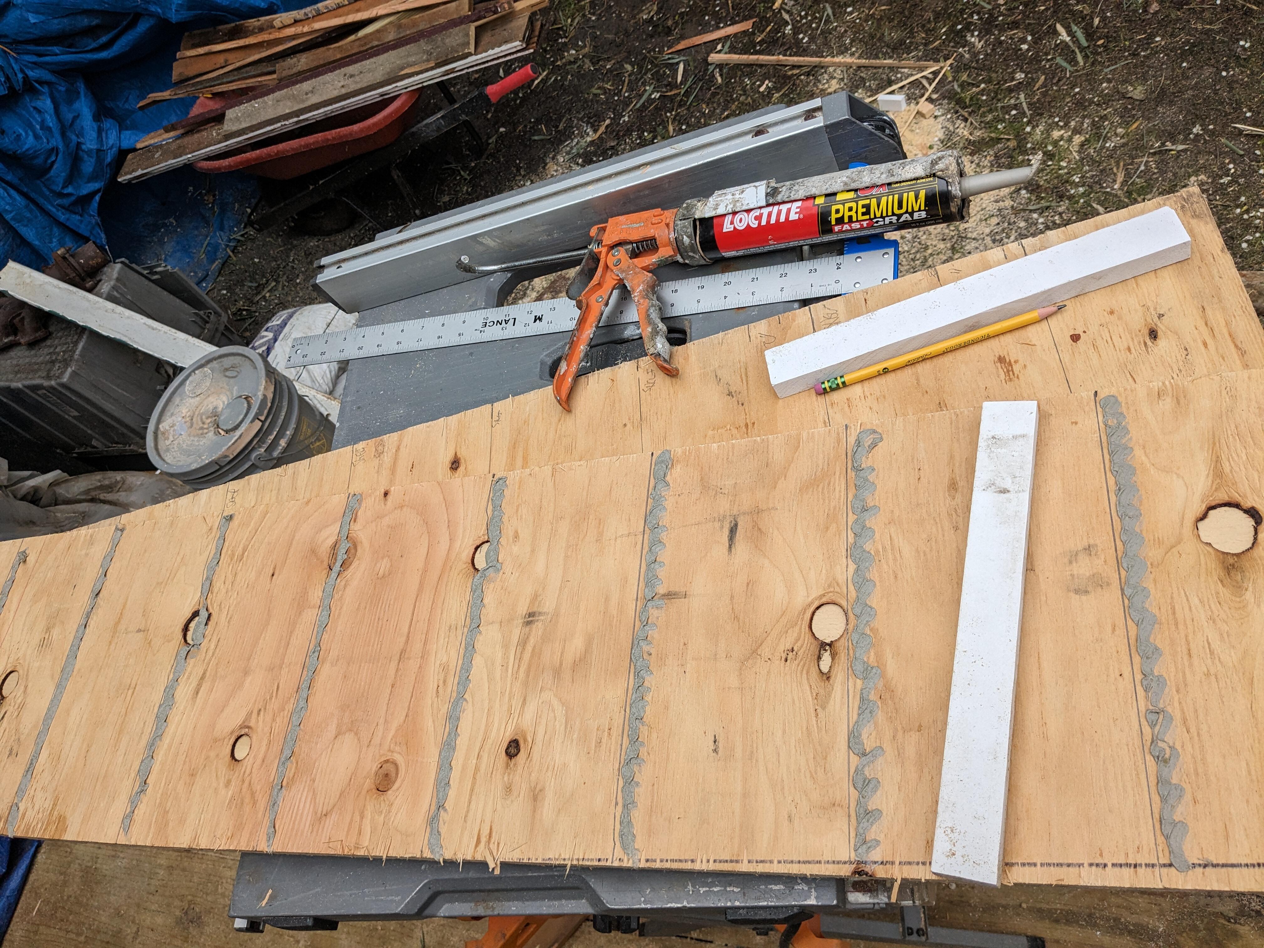
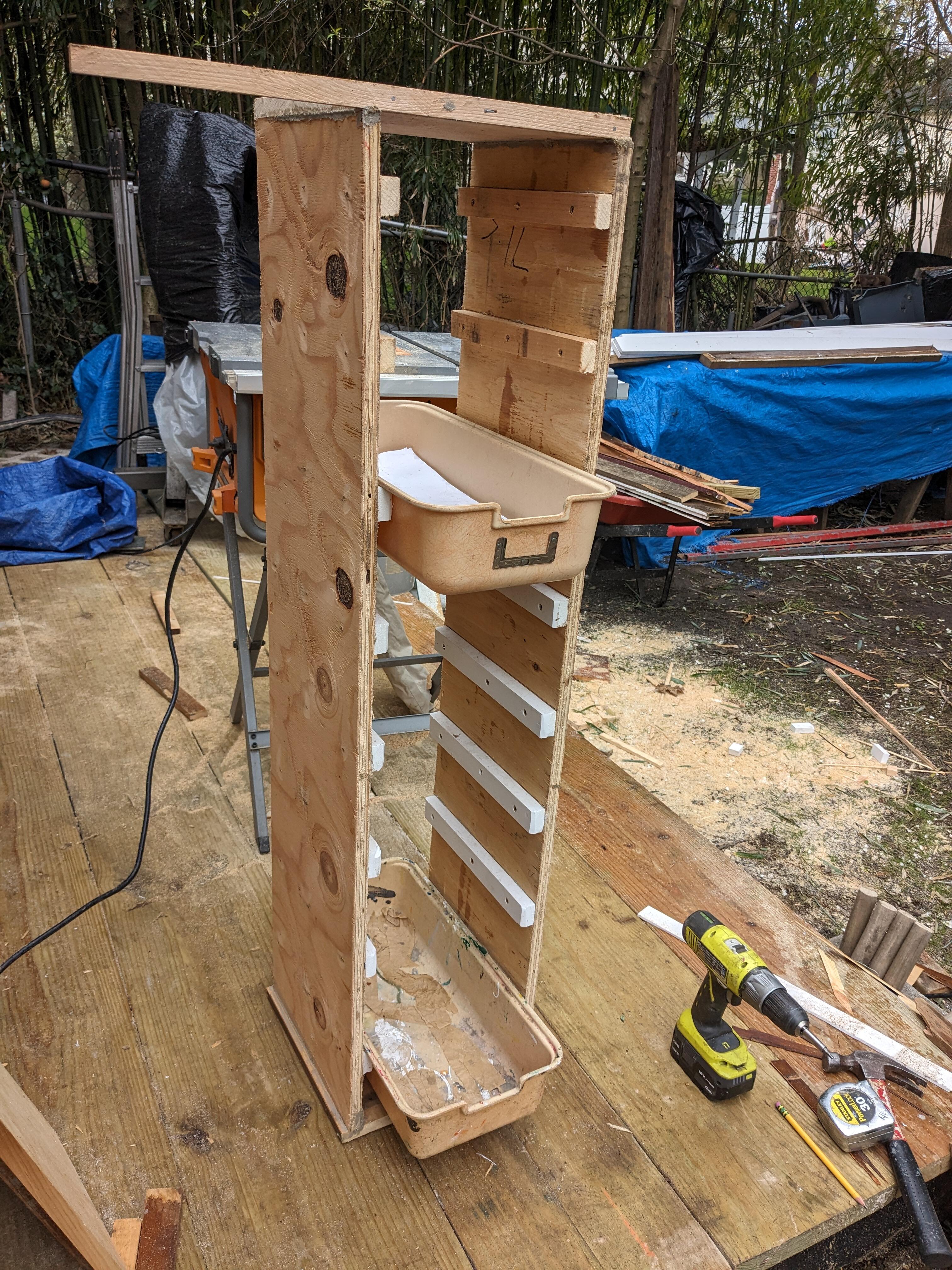
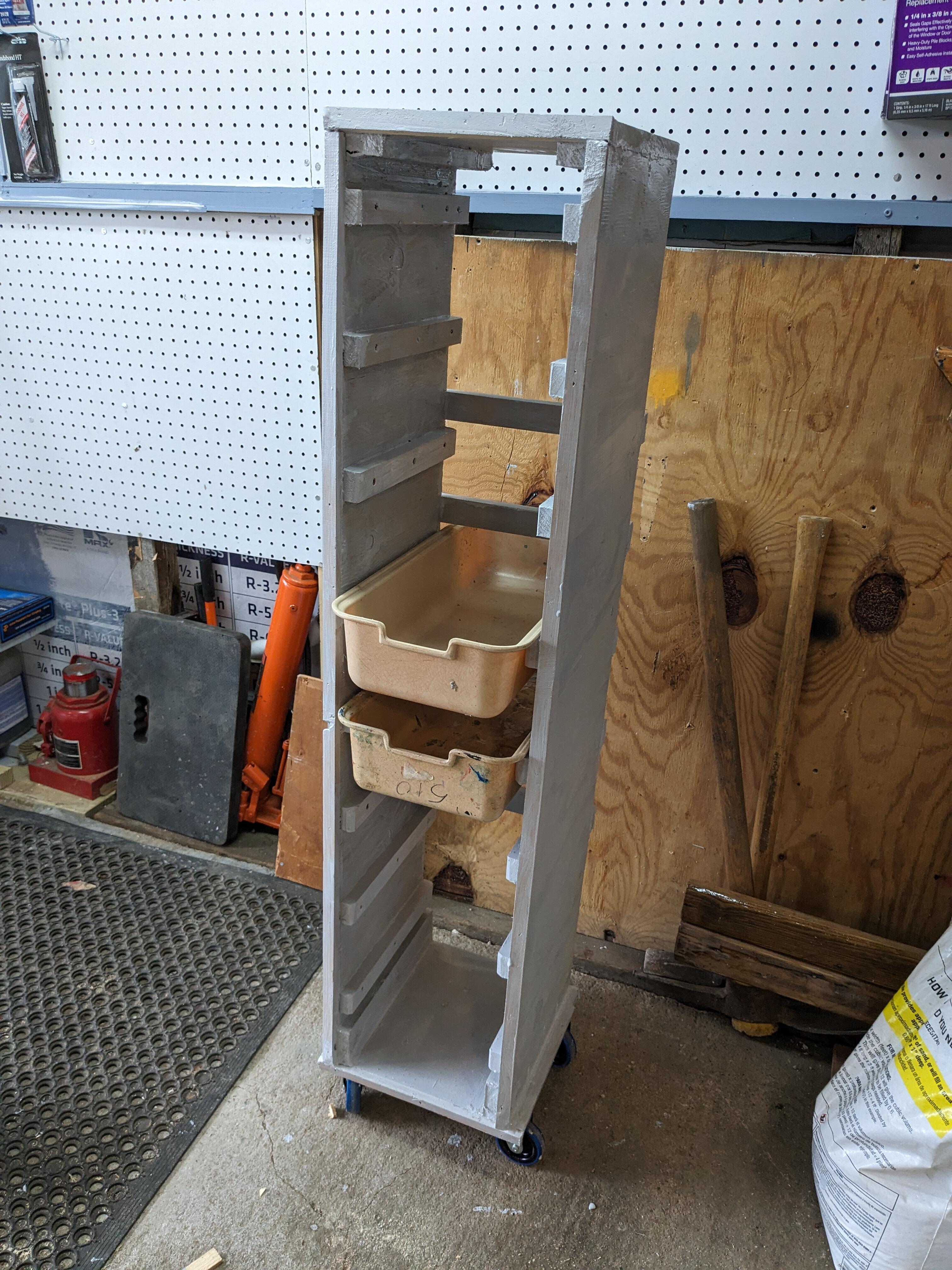
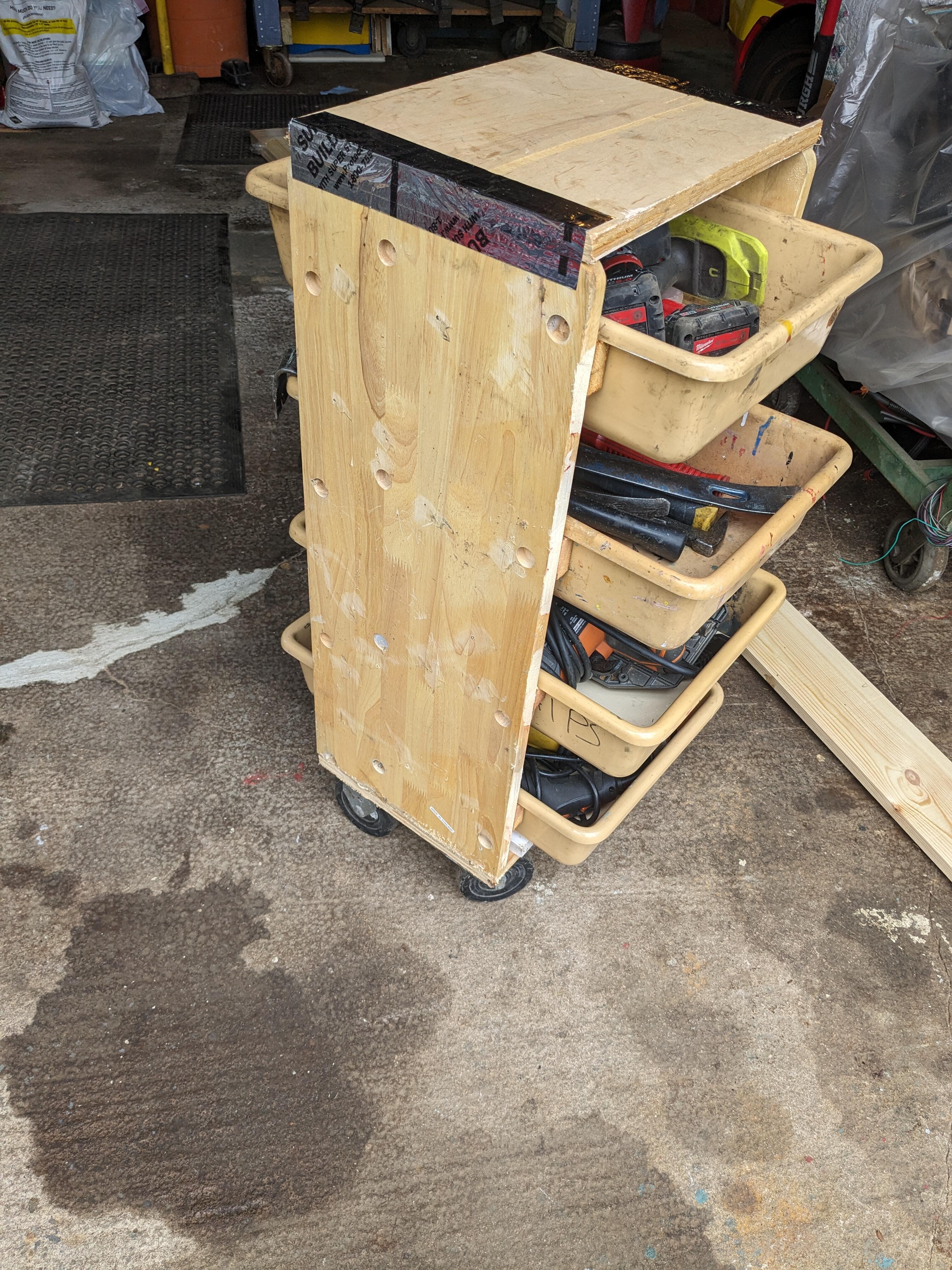
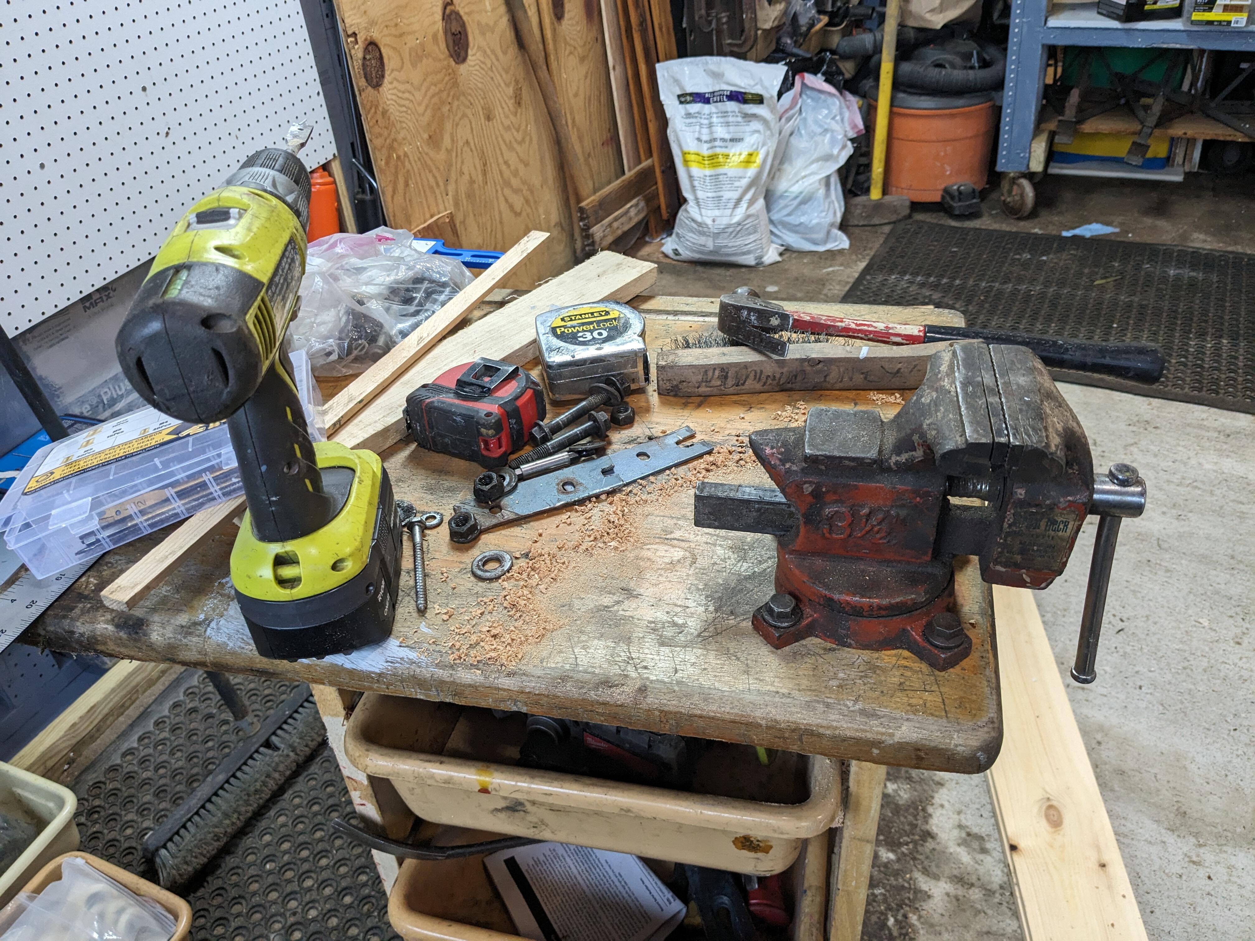
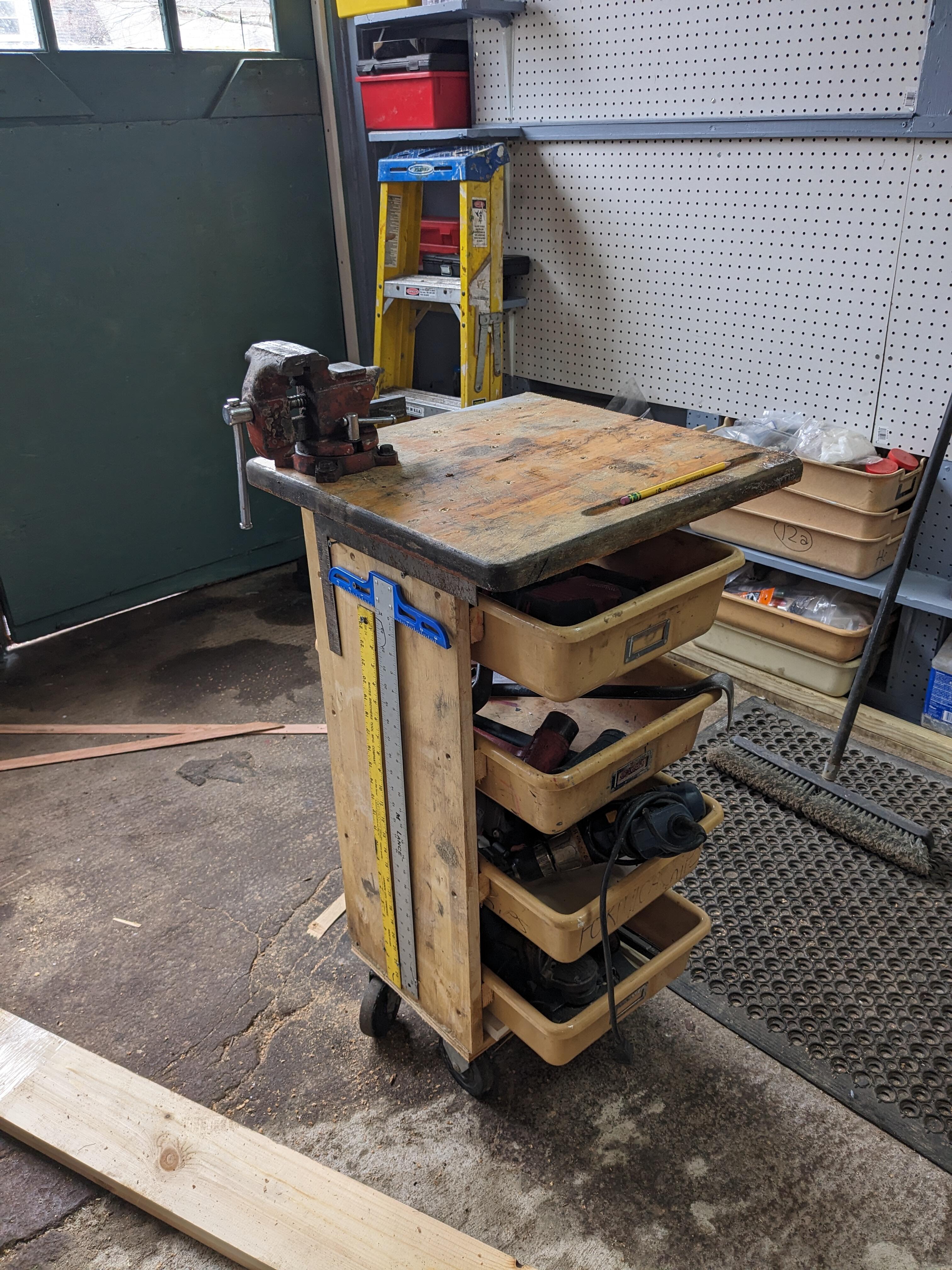
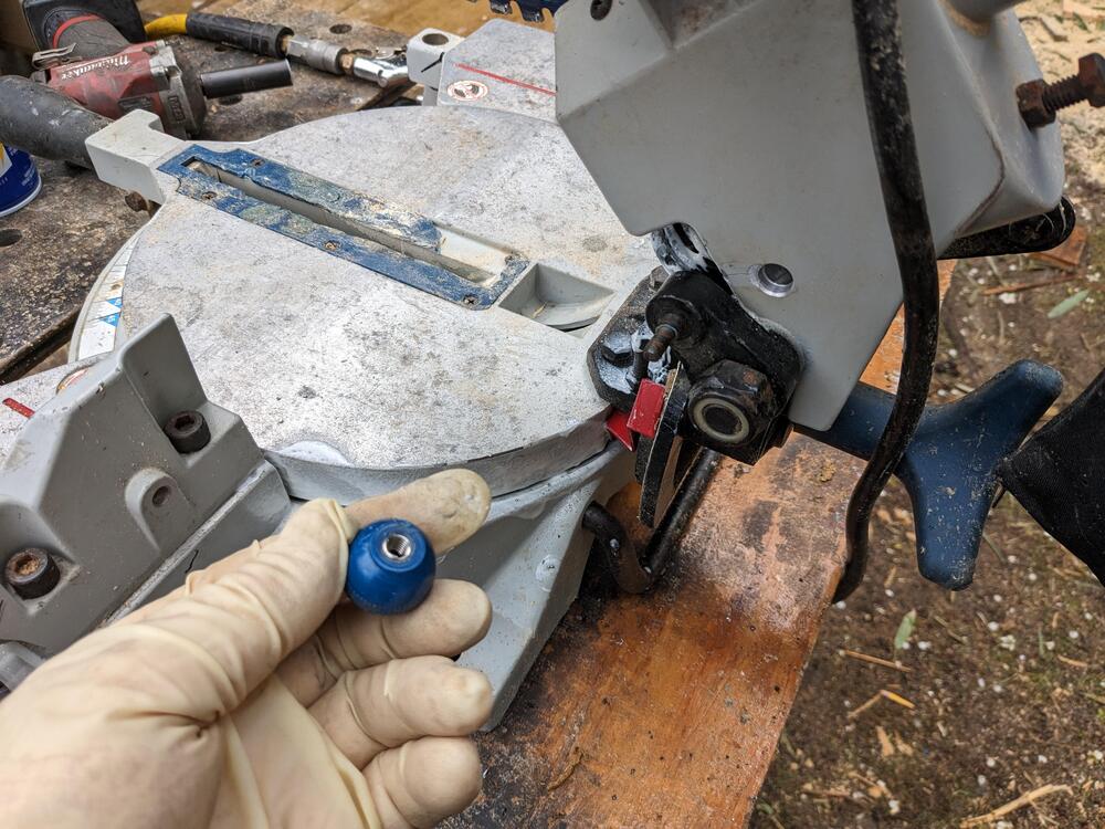
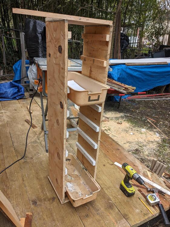
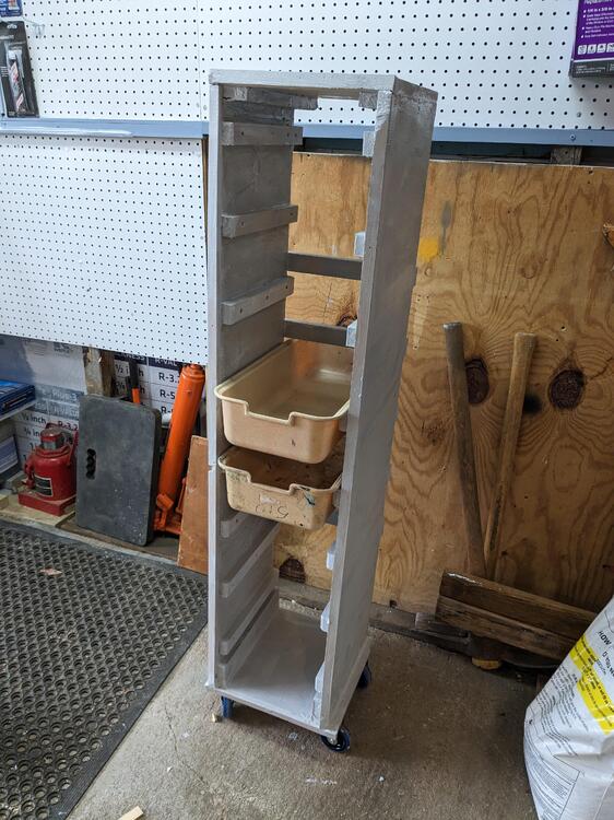
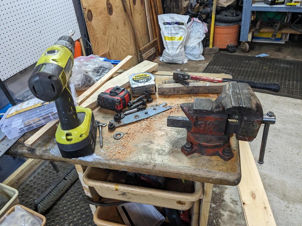
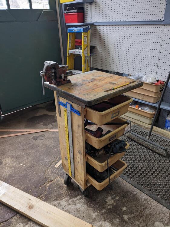
Hey Yarb - I didn't actually put a locking caster on it, I wasn't planning on using that small vice for anything industrial. I was thinking more just as a holding device for something that I might have to tack weid etc. I actually used it today to hold the ballnut from my chop saw, the thread strip and I had to put it insert in it. The vice was perfect for that . There is now a harbor freight, within about 5 minutes of my home, so I can easily get a locking caster if it should become a requirement. Fabricated the other wheelie cart for the narrow trays this one will hold eight, it is on the toll side, however they are all essentially lightweight as I use them to contain rubber bushings/grommets, body clips, various sealants, and so forth. Rained on and off all day today - so not much else accomplished. I did get this primed, and also I did get the caulking on the other side of the eave in the front of the garage. Really cool display yesterday evening - it's rained again after this one, and by the time we got to town, there was a clear double rainbow. Hard to photograph. It was also in the first one, but less obvious, to me anyway


-
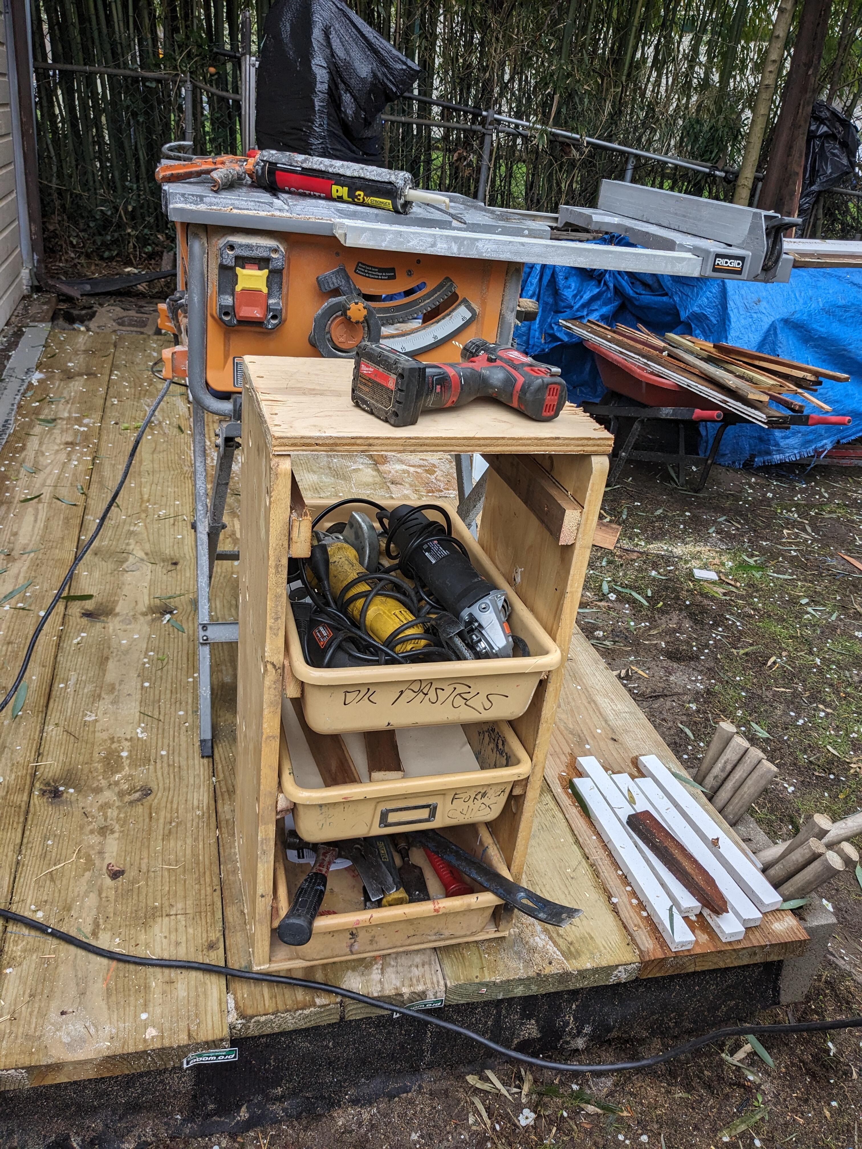
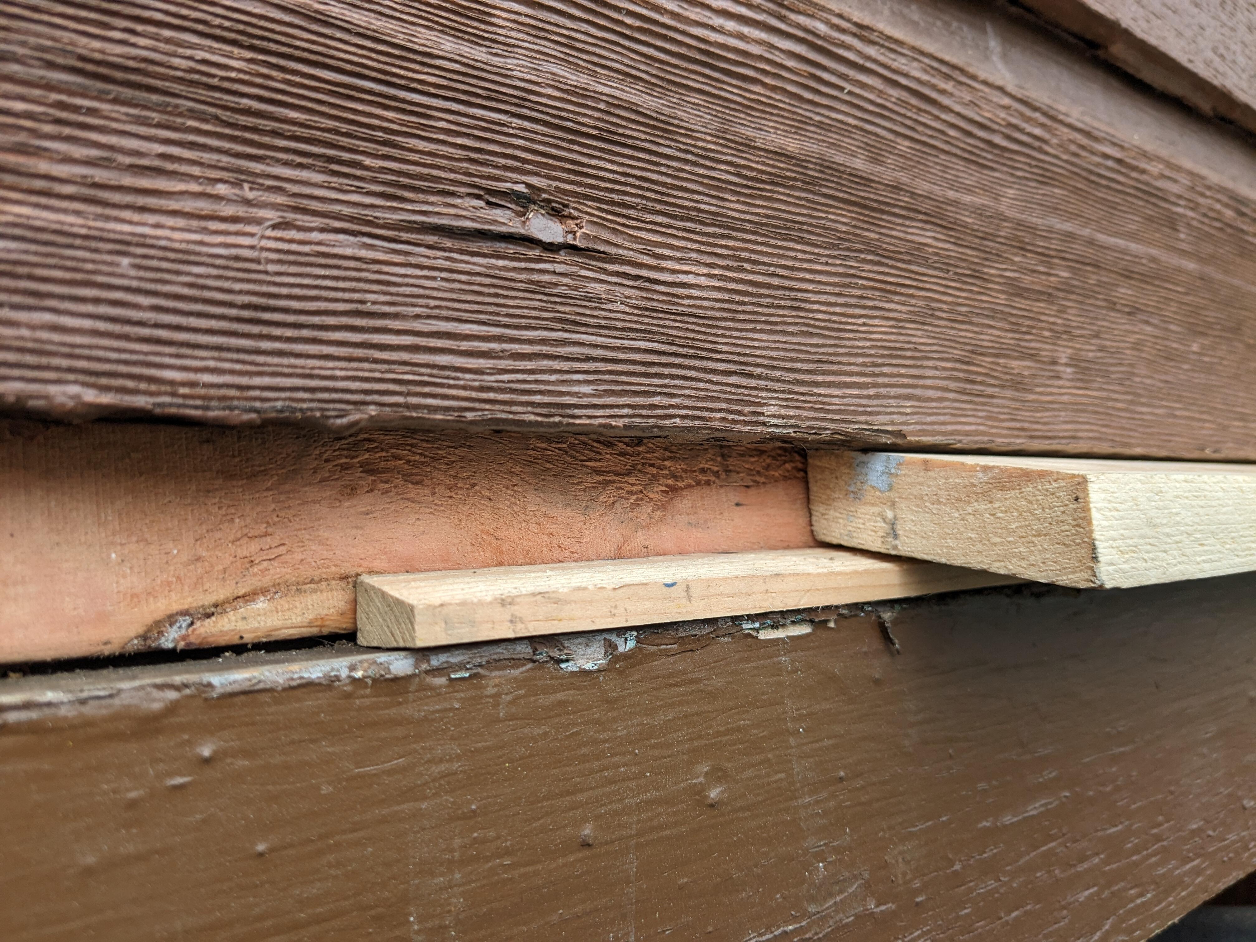
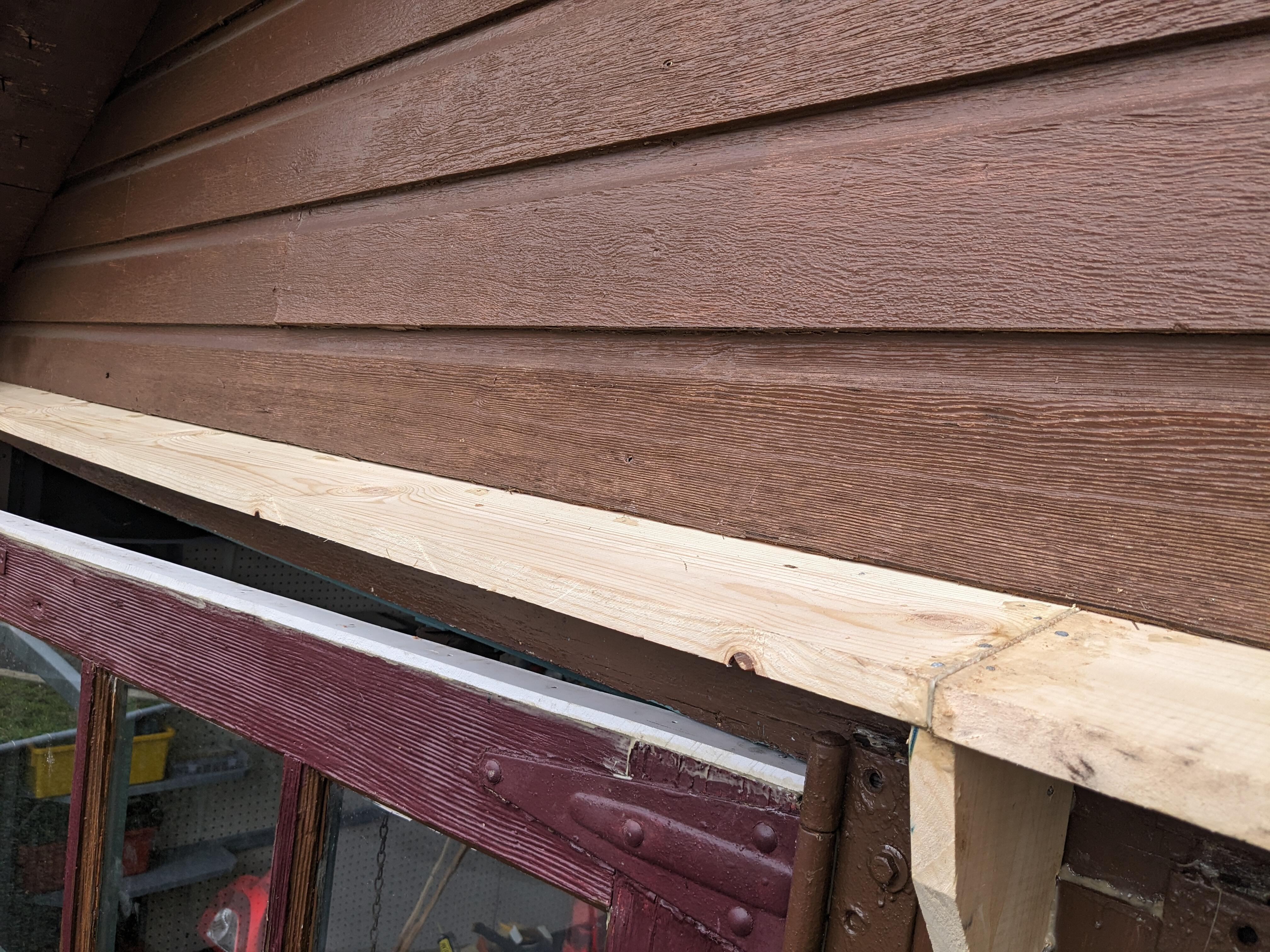
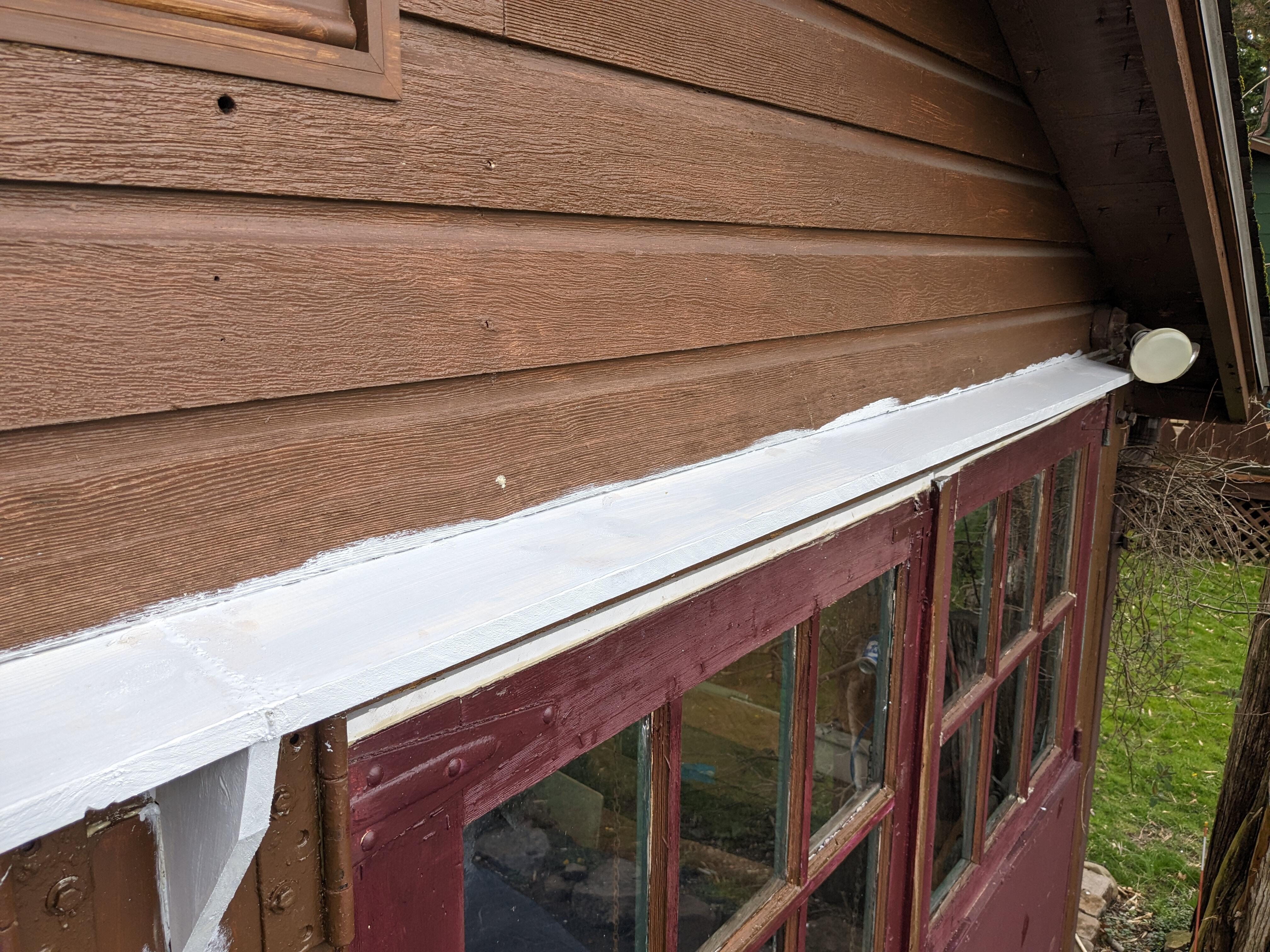
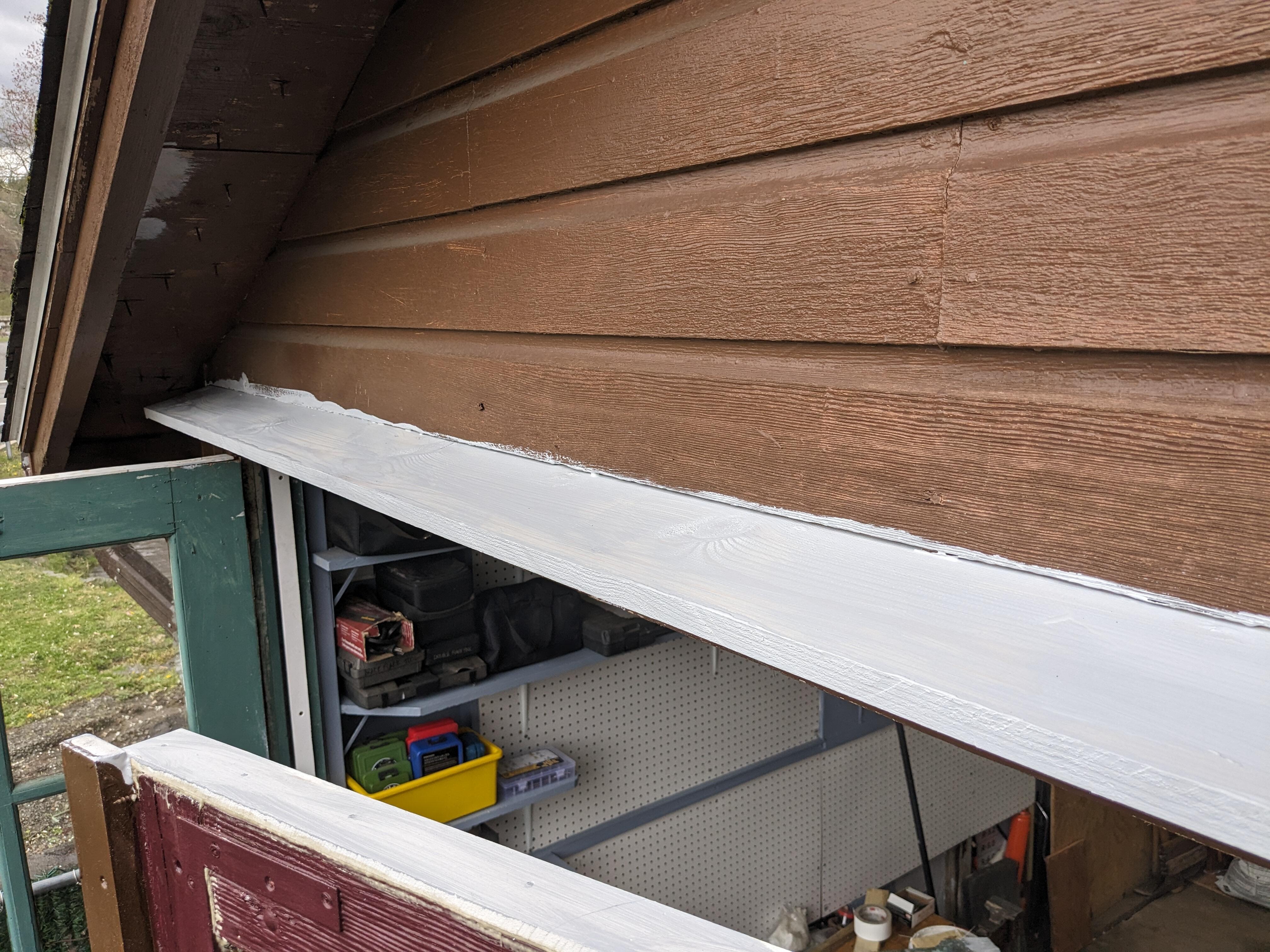
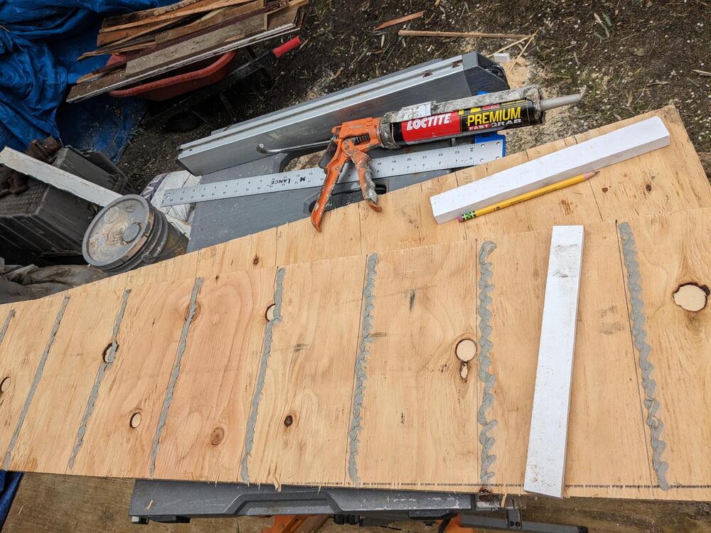
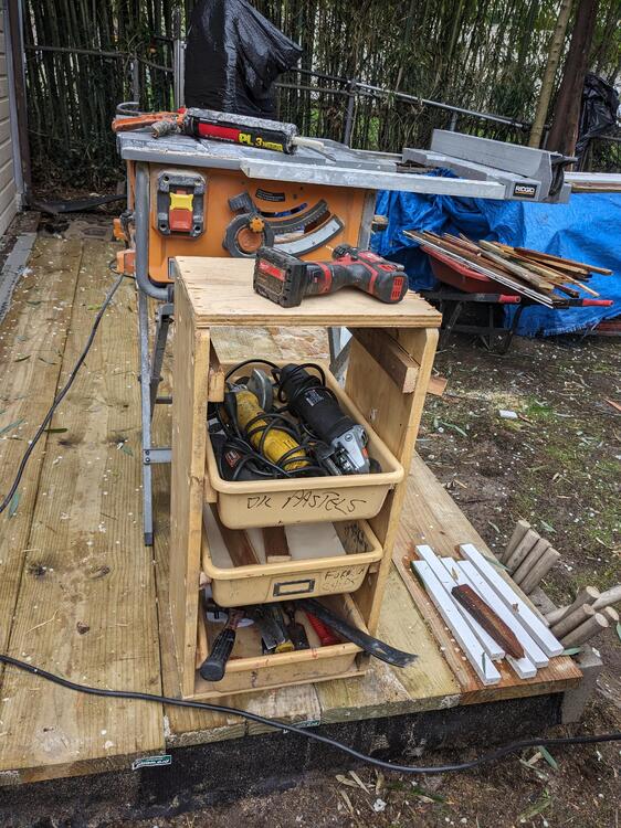
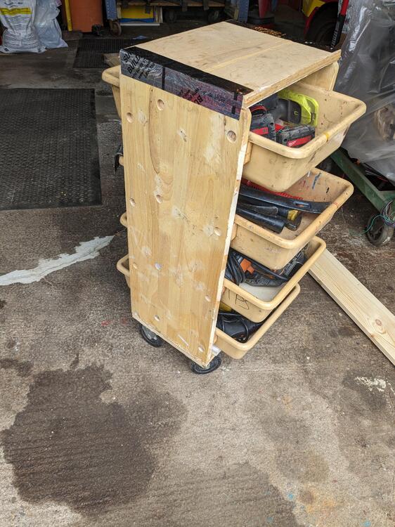
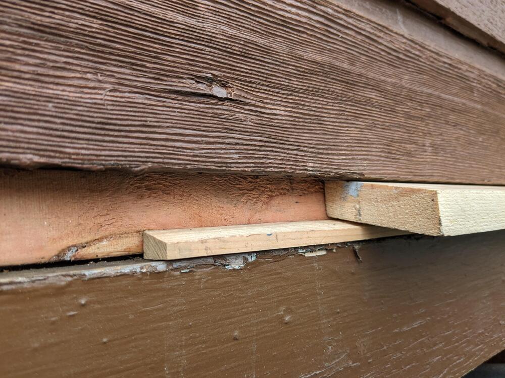
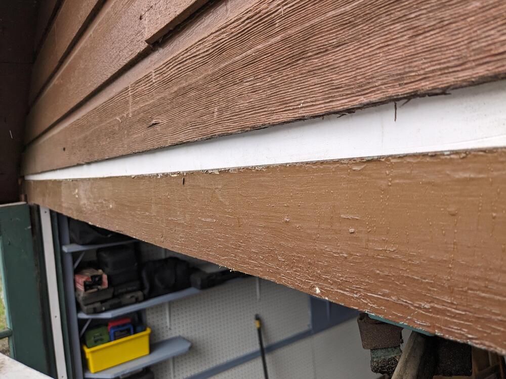
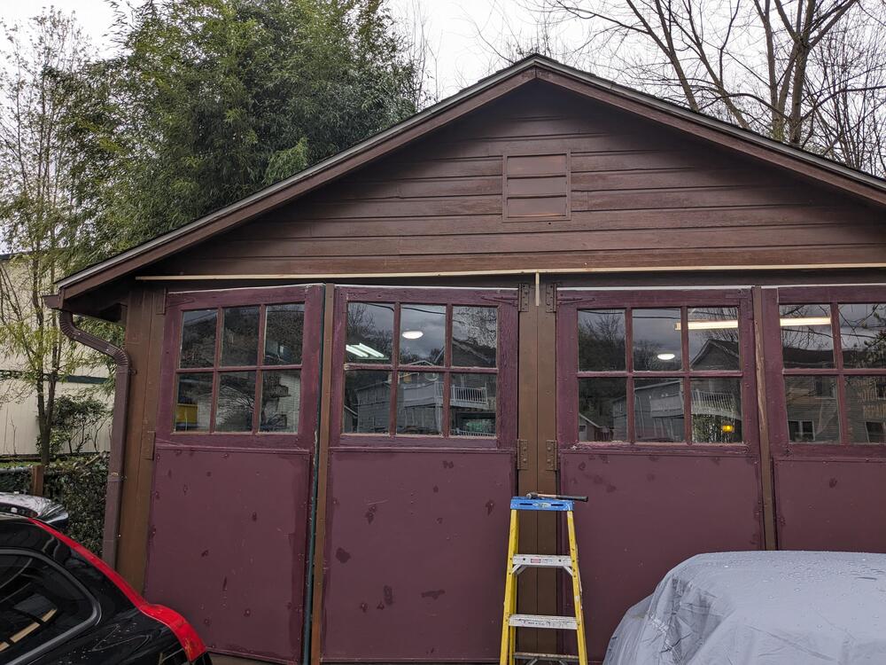
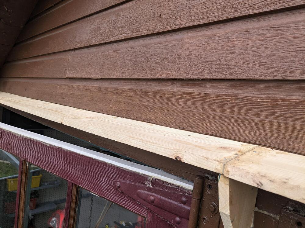
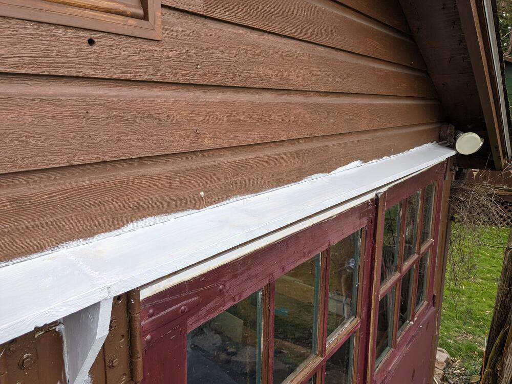
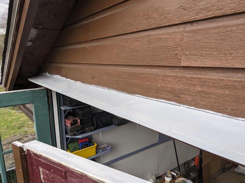
Made a wheelie cart to hold the bins I have. Now I need to make another for the narrower bins that I was going to put against the wall Decided I might as well make it a mini bench with a small vice Eave test with scraps - cut to 12 degrees, with a 3/8" filler also cut to 12 degrees put the PVA in the siding gap cut & fitted the actual eave. Made a center support, since I couldn't do a single 18' run and got primer on it. I'll caulk it tomorrow.
-
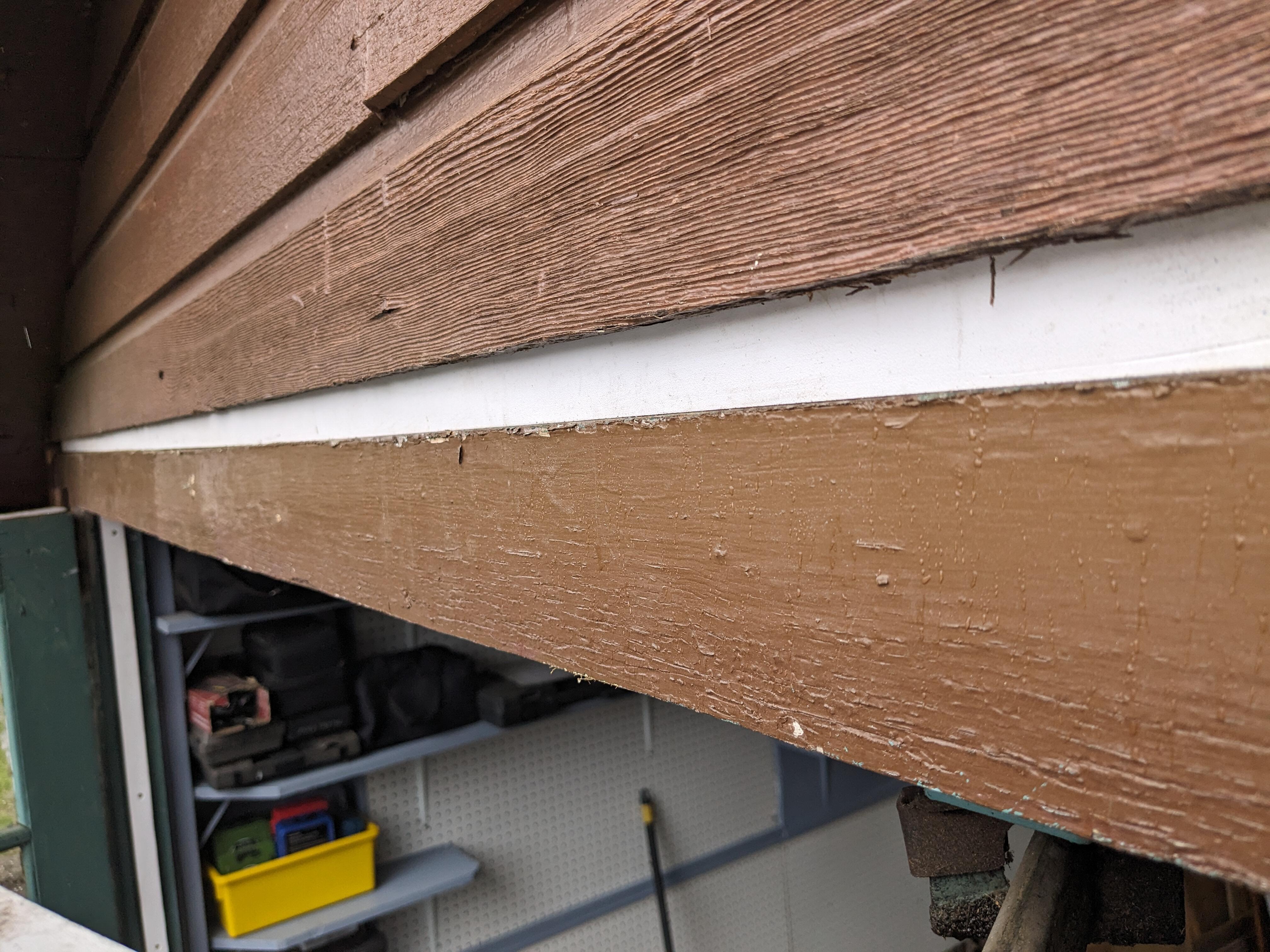
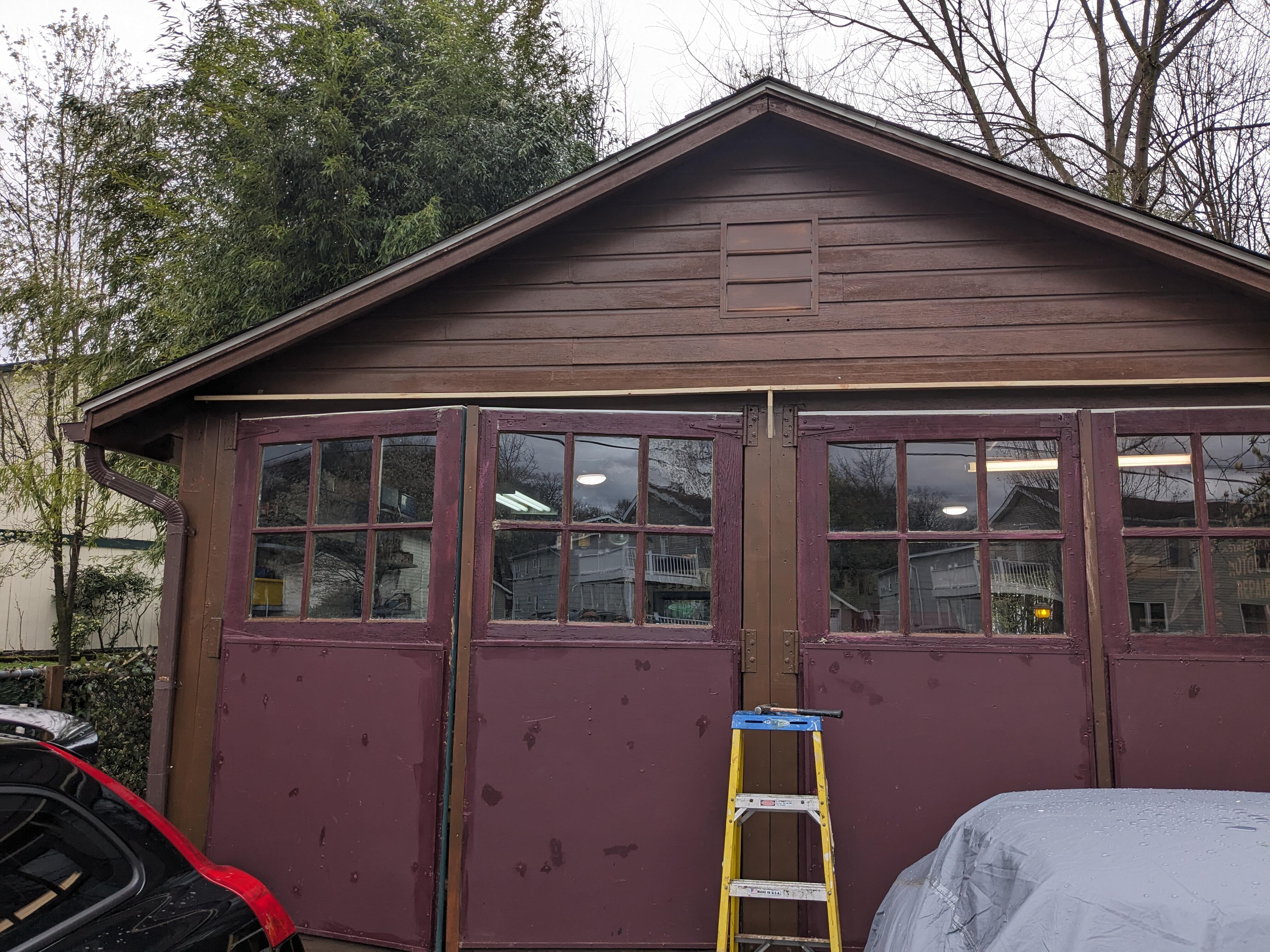
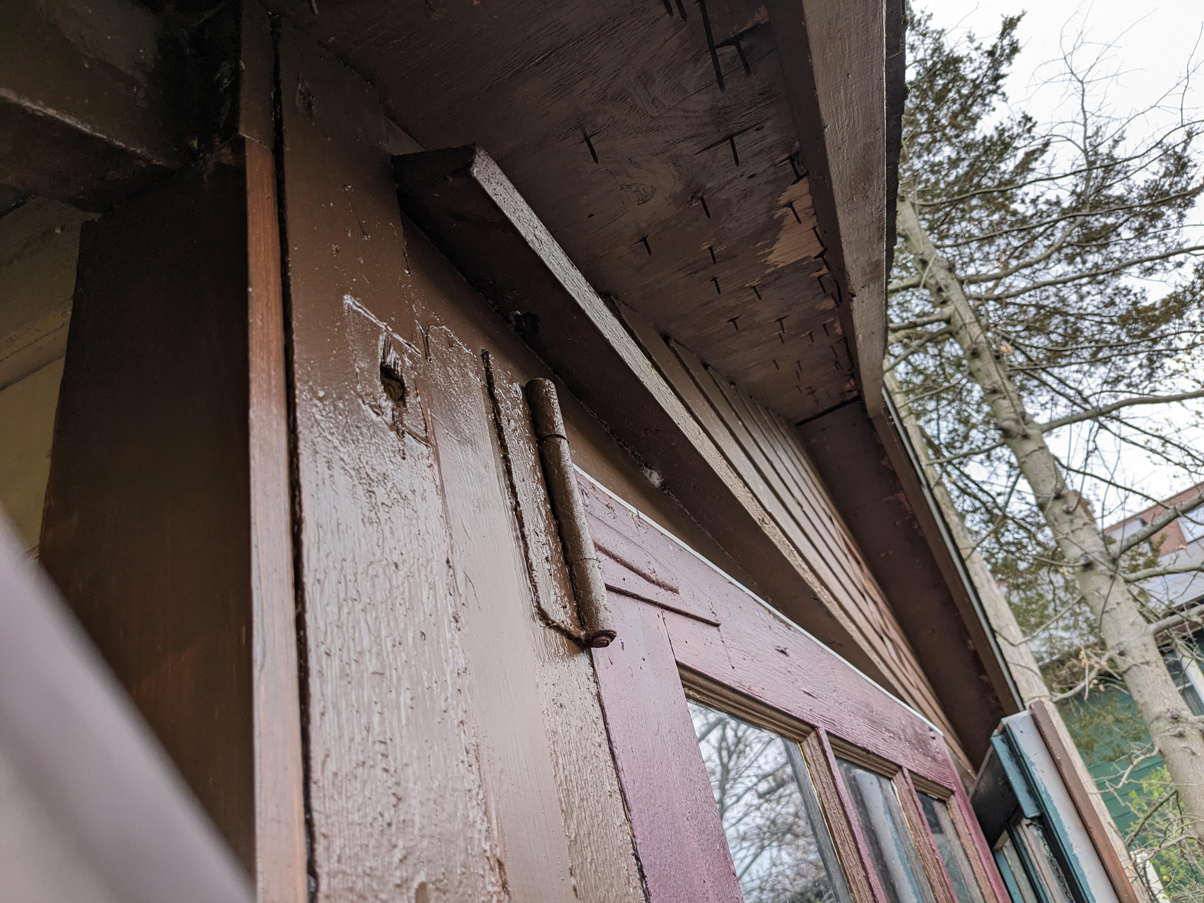
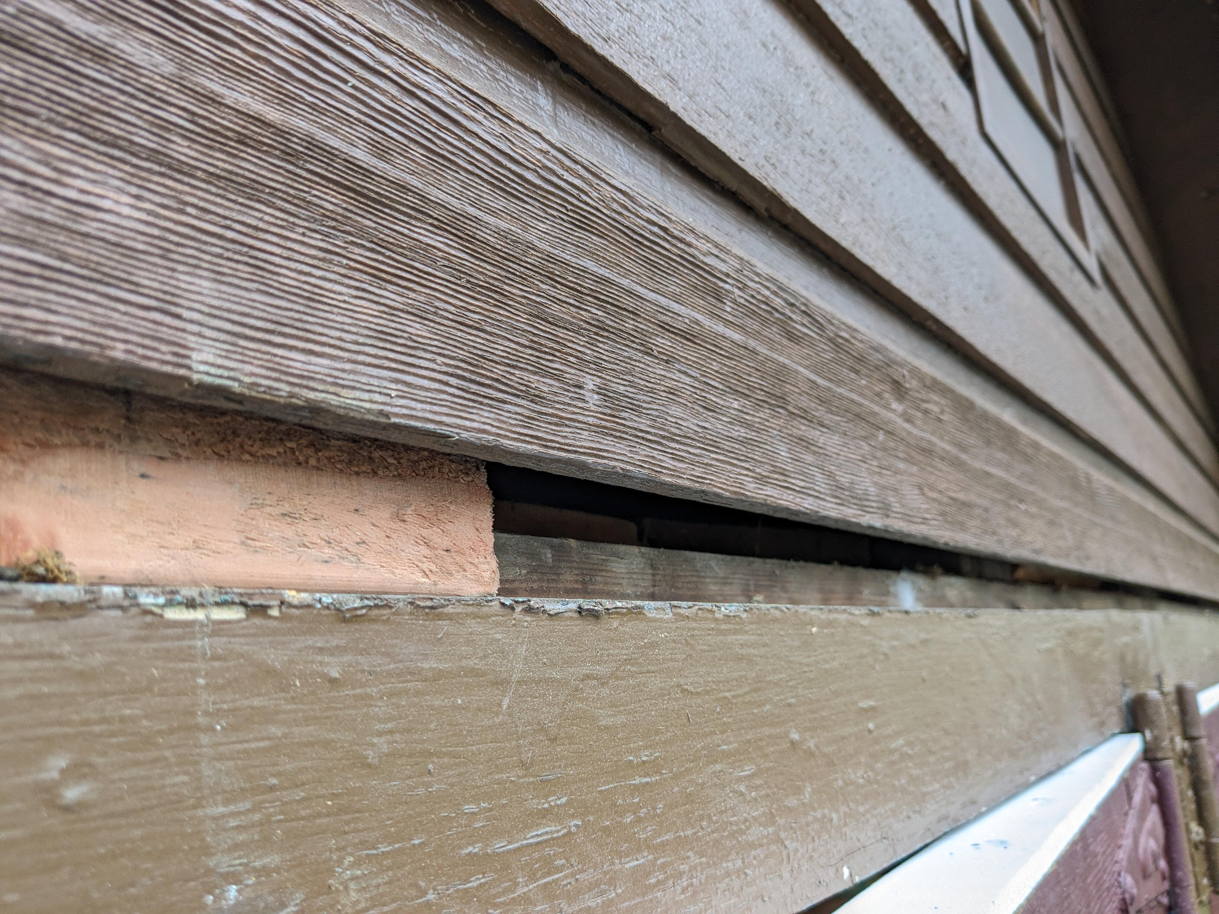
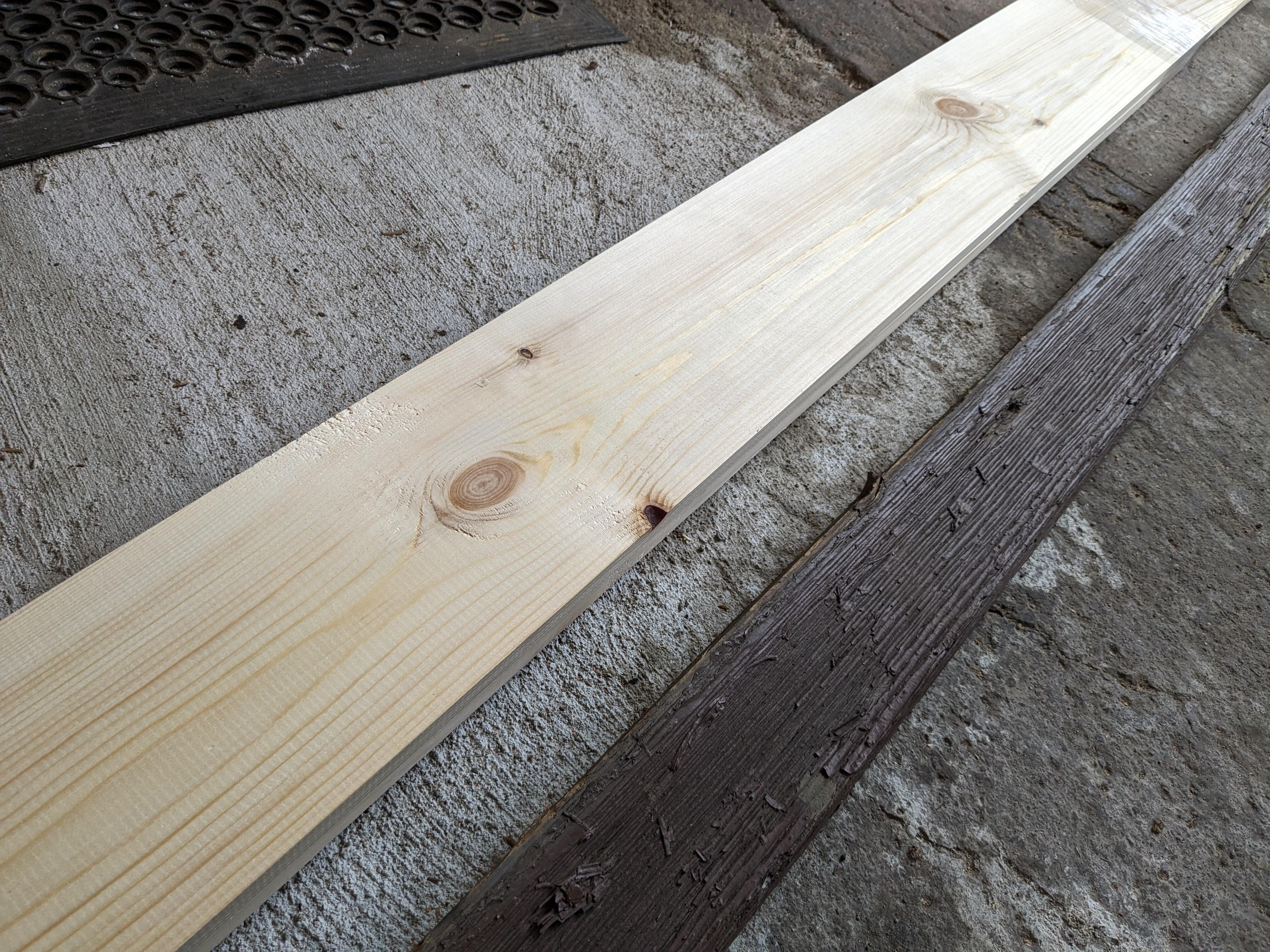
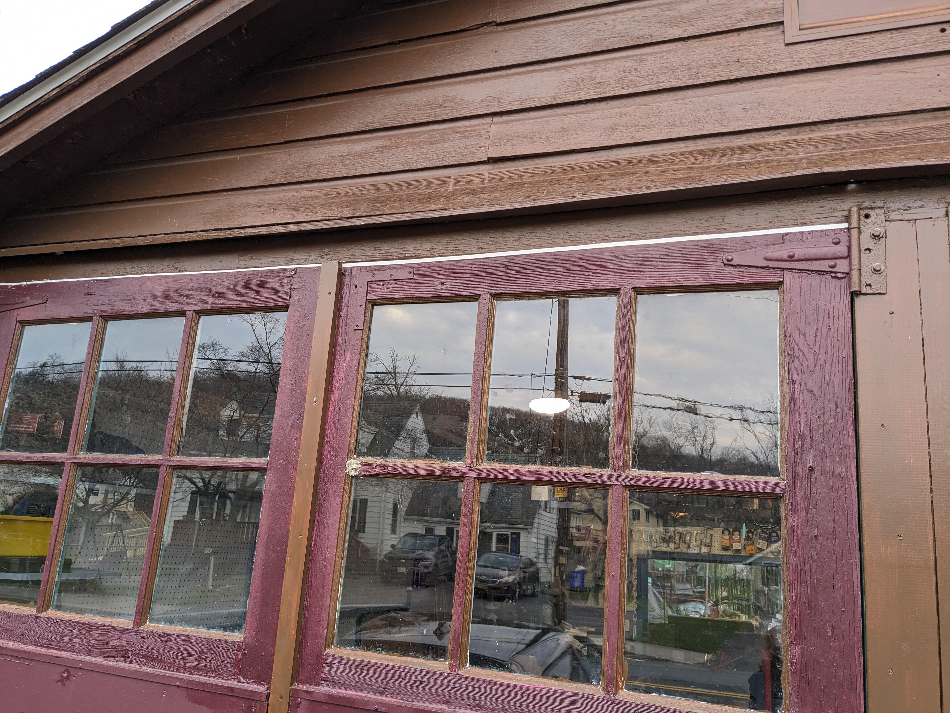
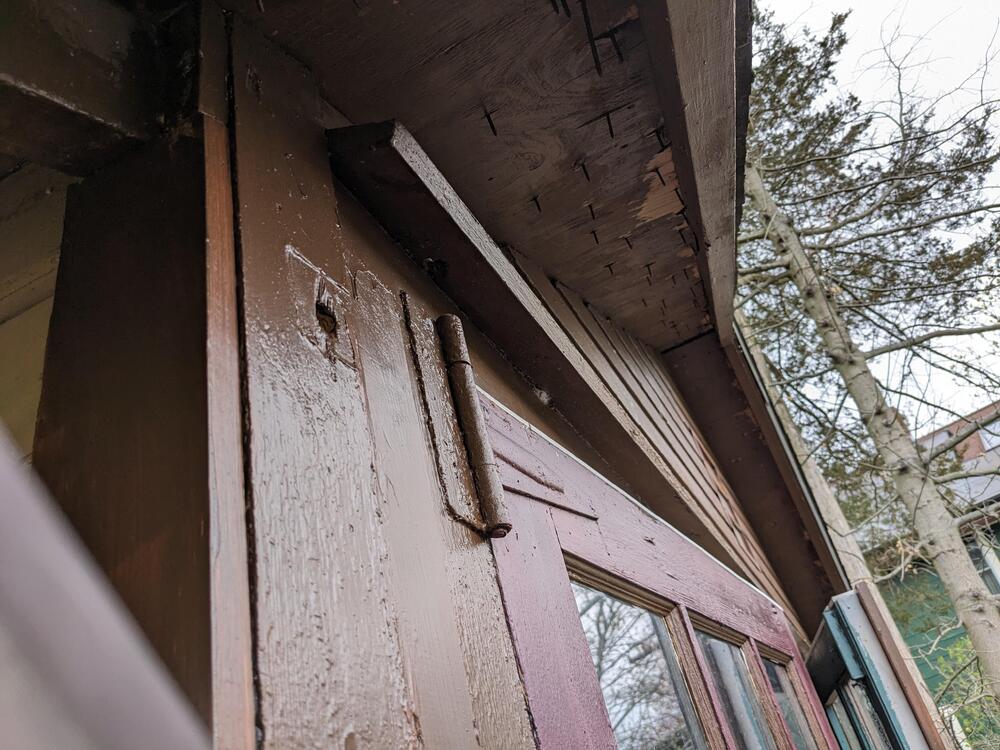
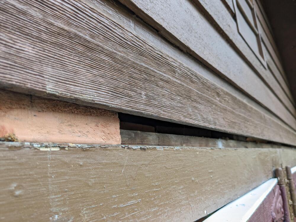
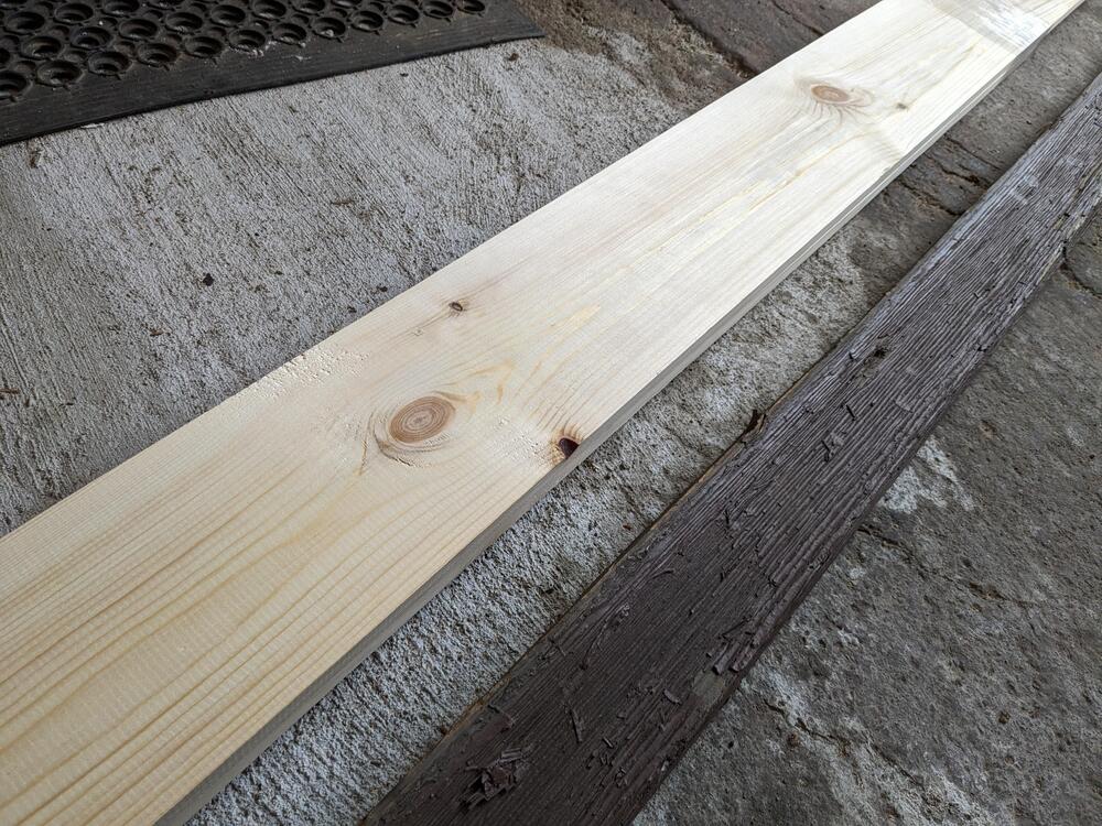
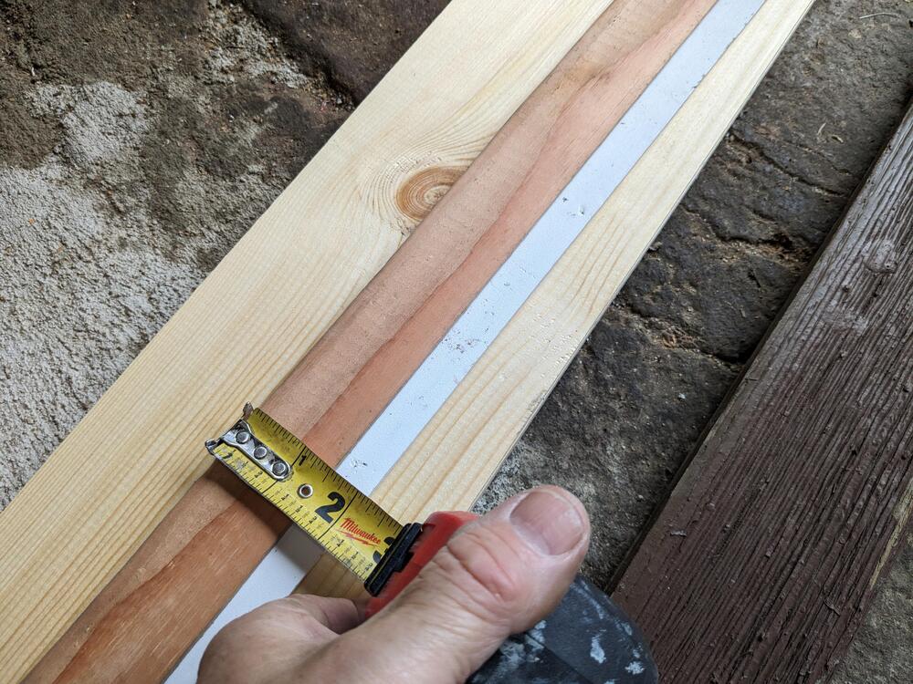
Thank you 😊 Started on the eave(?) above the doors. Removed the damaged one, to find (of course) that there are additional issues. need to add a 1.5" strip to seal the gap that exists behind the eave. I'm going to cut it from the extra PVA I have, don't have to worry about rot with that. I bought 1X6 pine instead of the shallower 1x4 for a deeper overhang of the doors
-
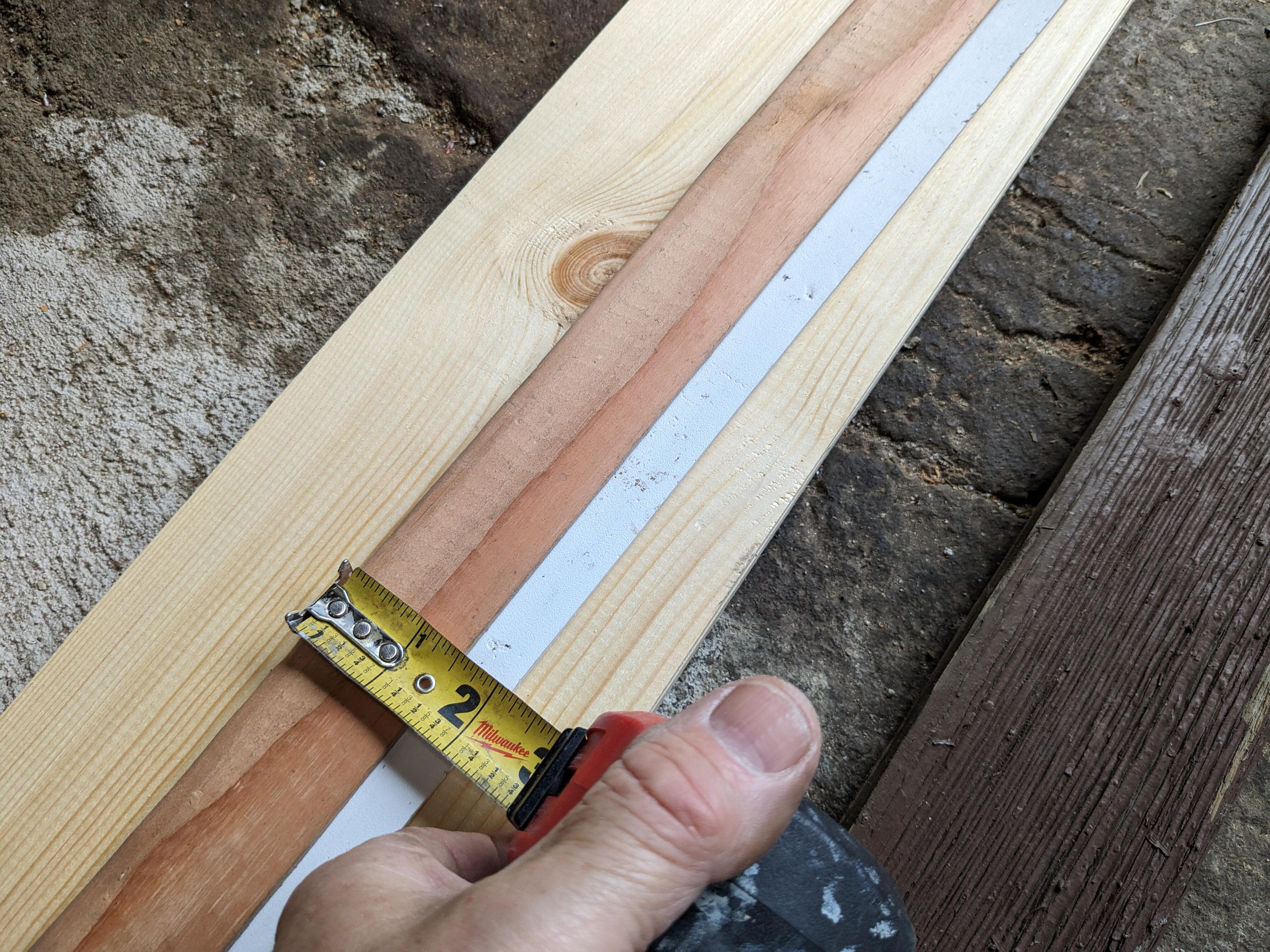
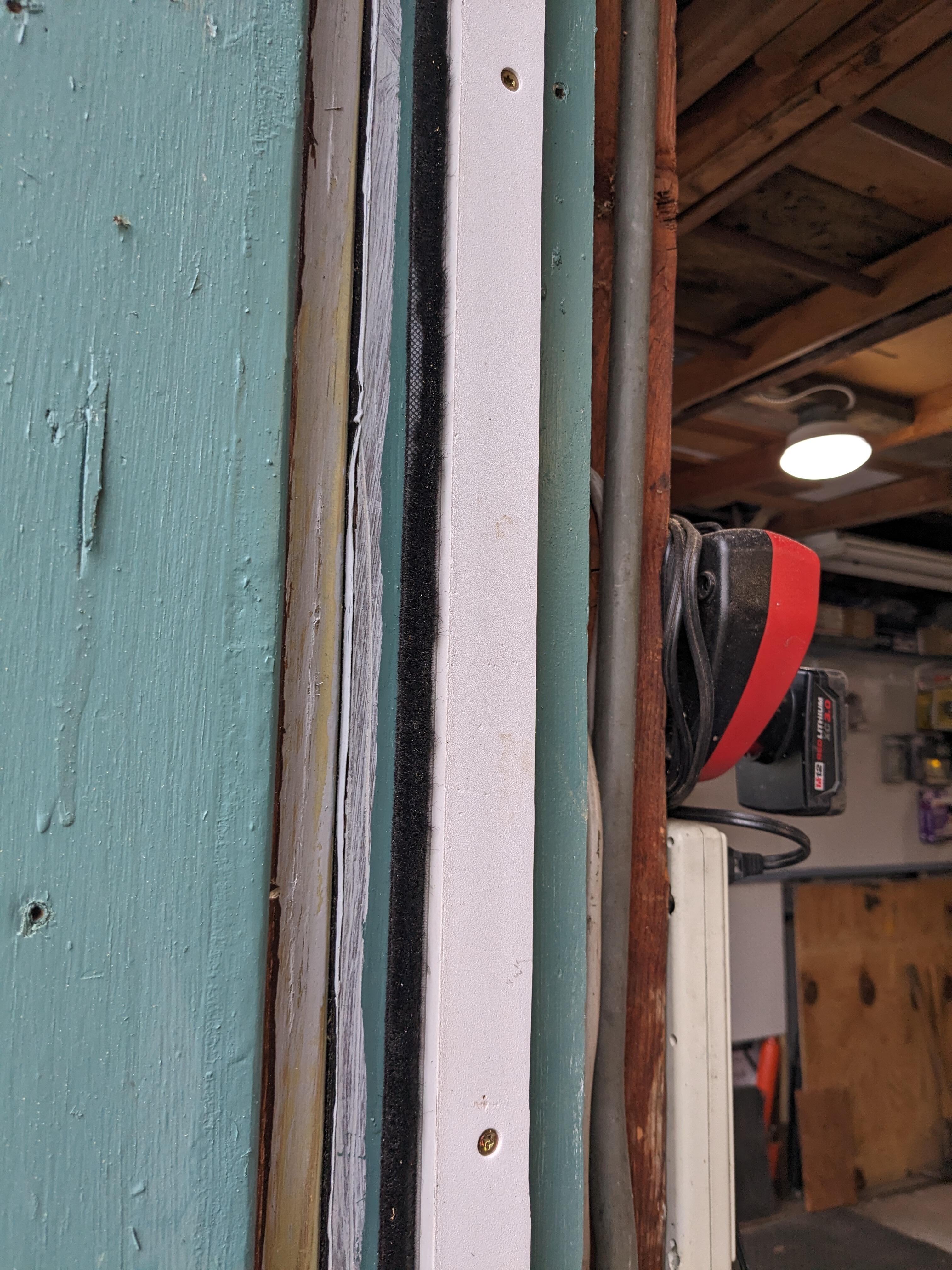
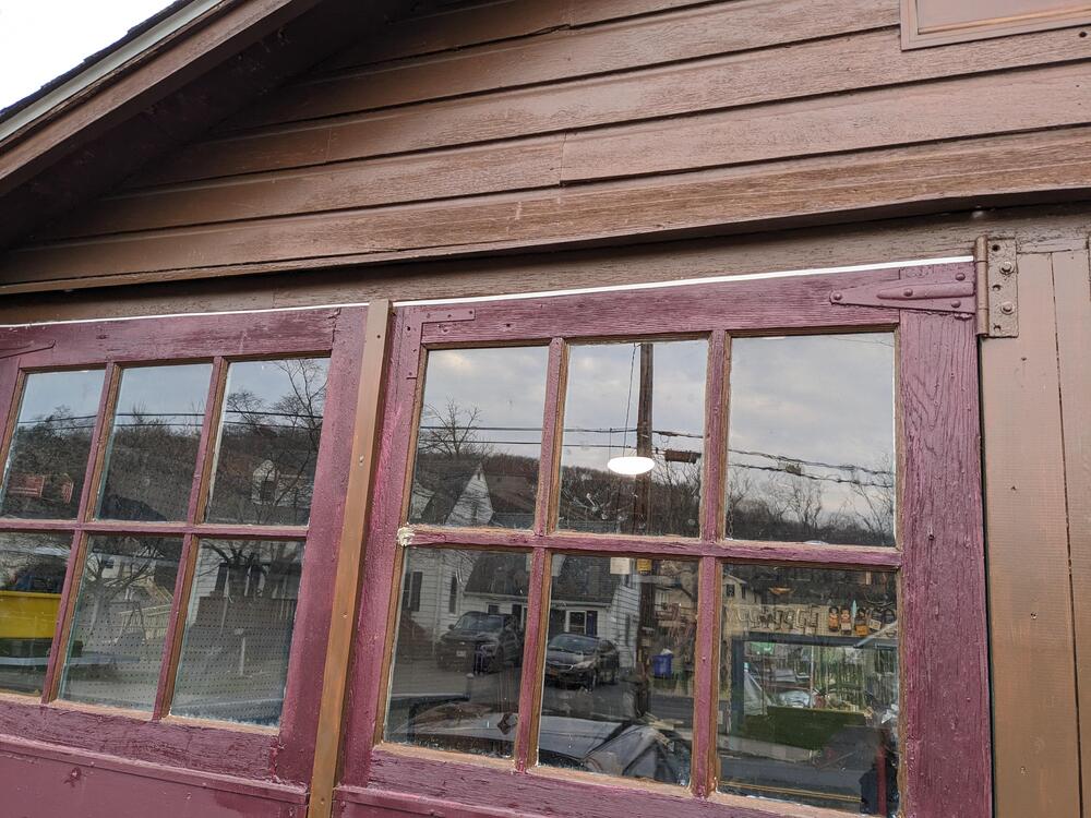
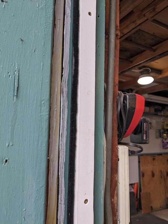
Just been futzIng after work - cut 4 PVA vertical strips for the door to frame "seal". I added the soft brush style sealing used for vinyl windows (at least I think that's what it's intended for). Also leveled the tops of the doors and added PVA caps to fill the gaps in varying sizes. I'll add a brush seal to them also, to minimize the air gaps. With those I'll probably put the seal onto the PVA on the door, as it doesn't really like to stick to wood painted or not. Sticks just fine to vinyl. Have to deal with the irregular door bottoms also, now those are the main draft (visible in last pic of last post )
-
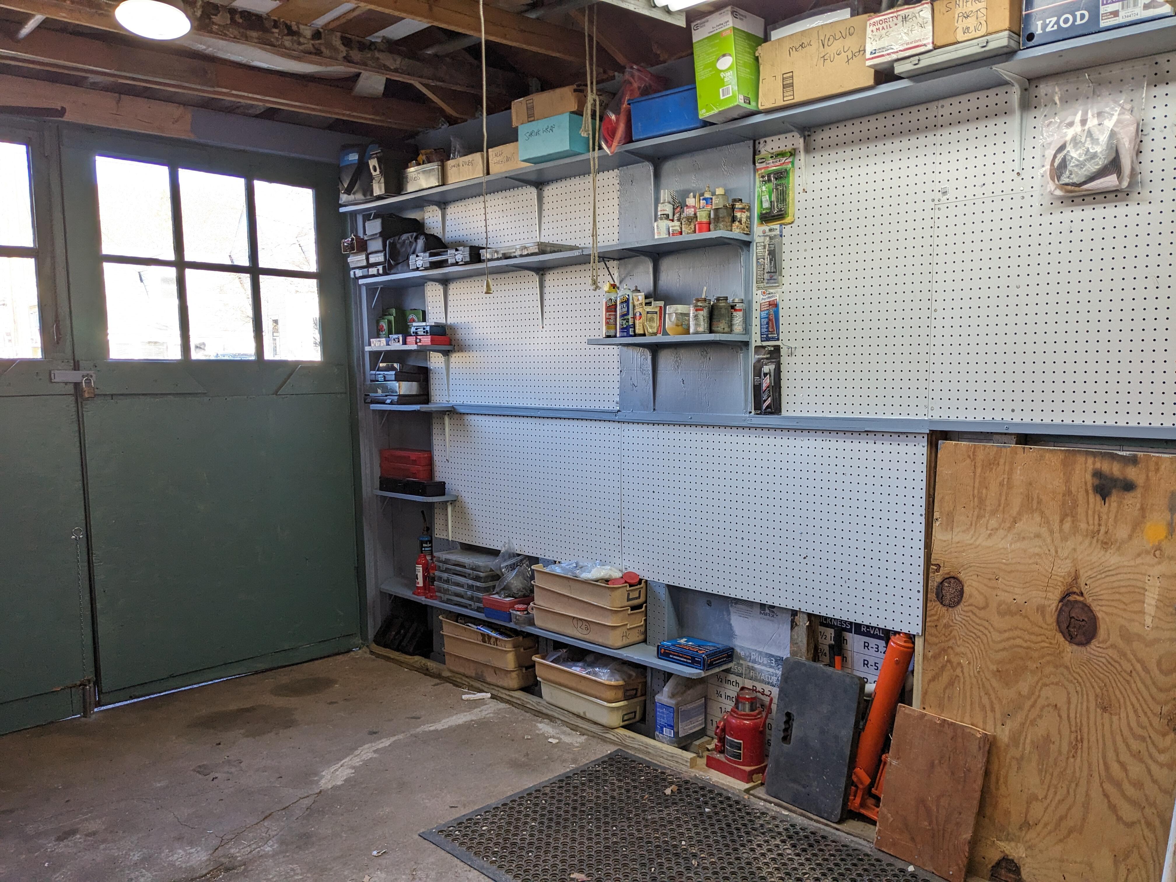
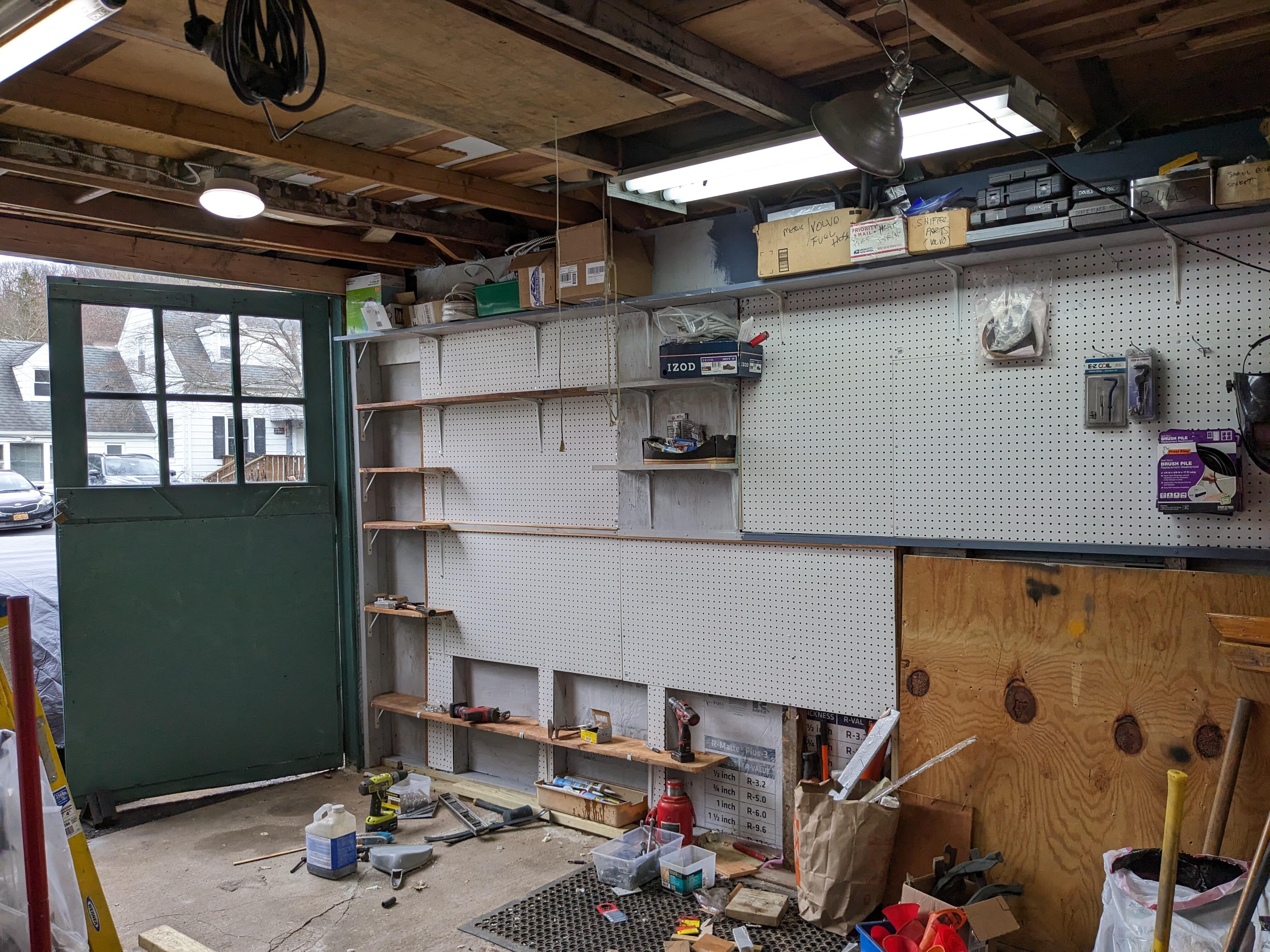
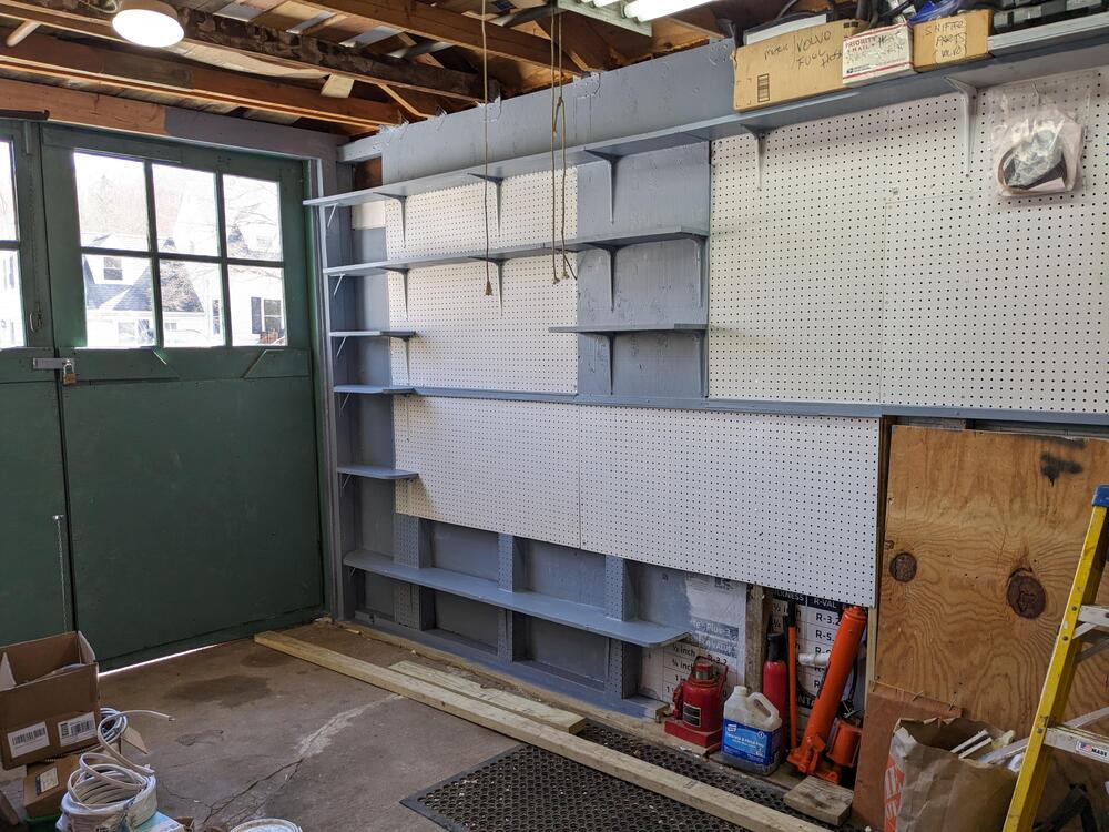
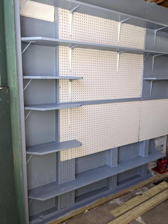
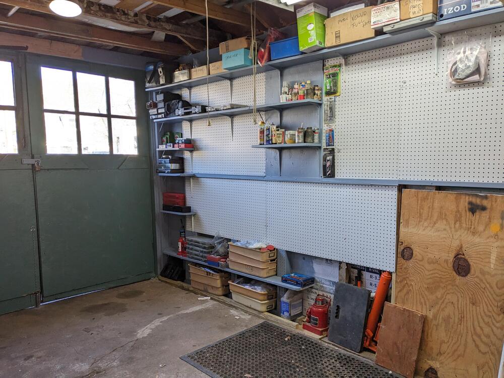
Many thanks. It truly is. This morning I had time to get a top coat on the shelves. I mixed a slightly lighter grey - the earlier version I felt was too dark for the sides Started putting stuff on them this afternoon. I'll be rearranging crap for sometime
-
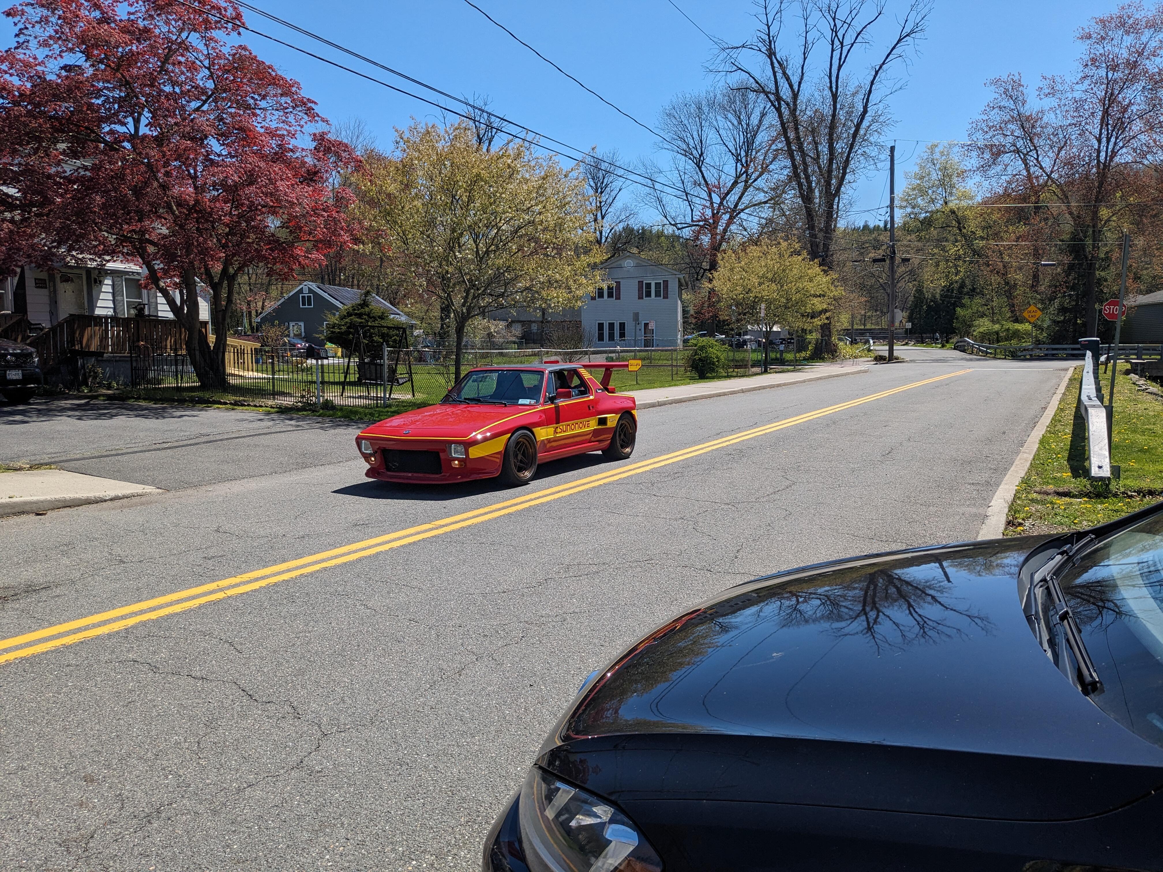
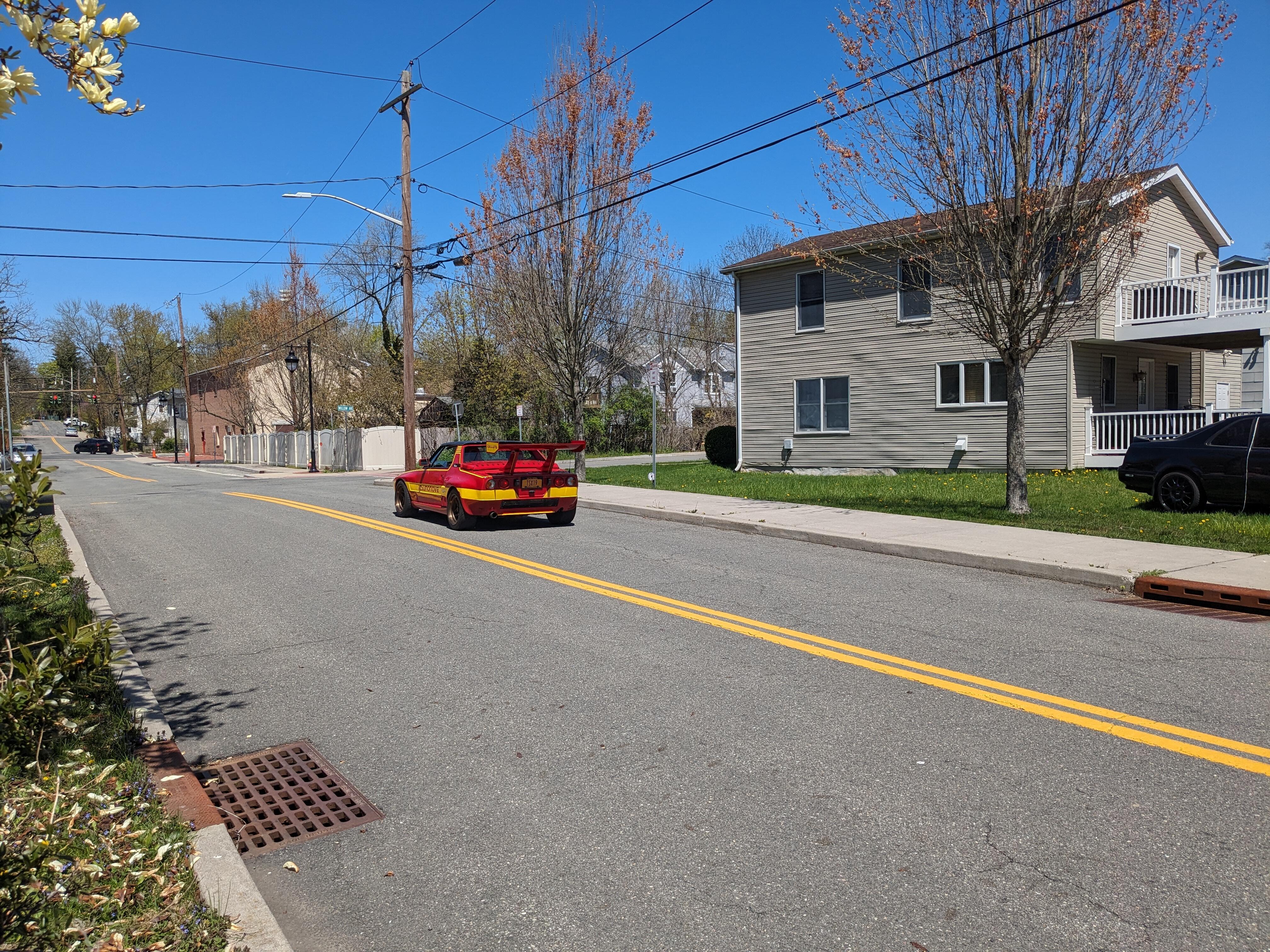
My X1/9 BaT auction is now live
-
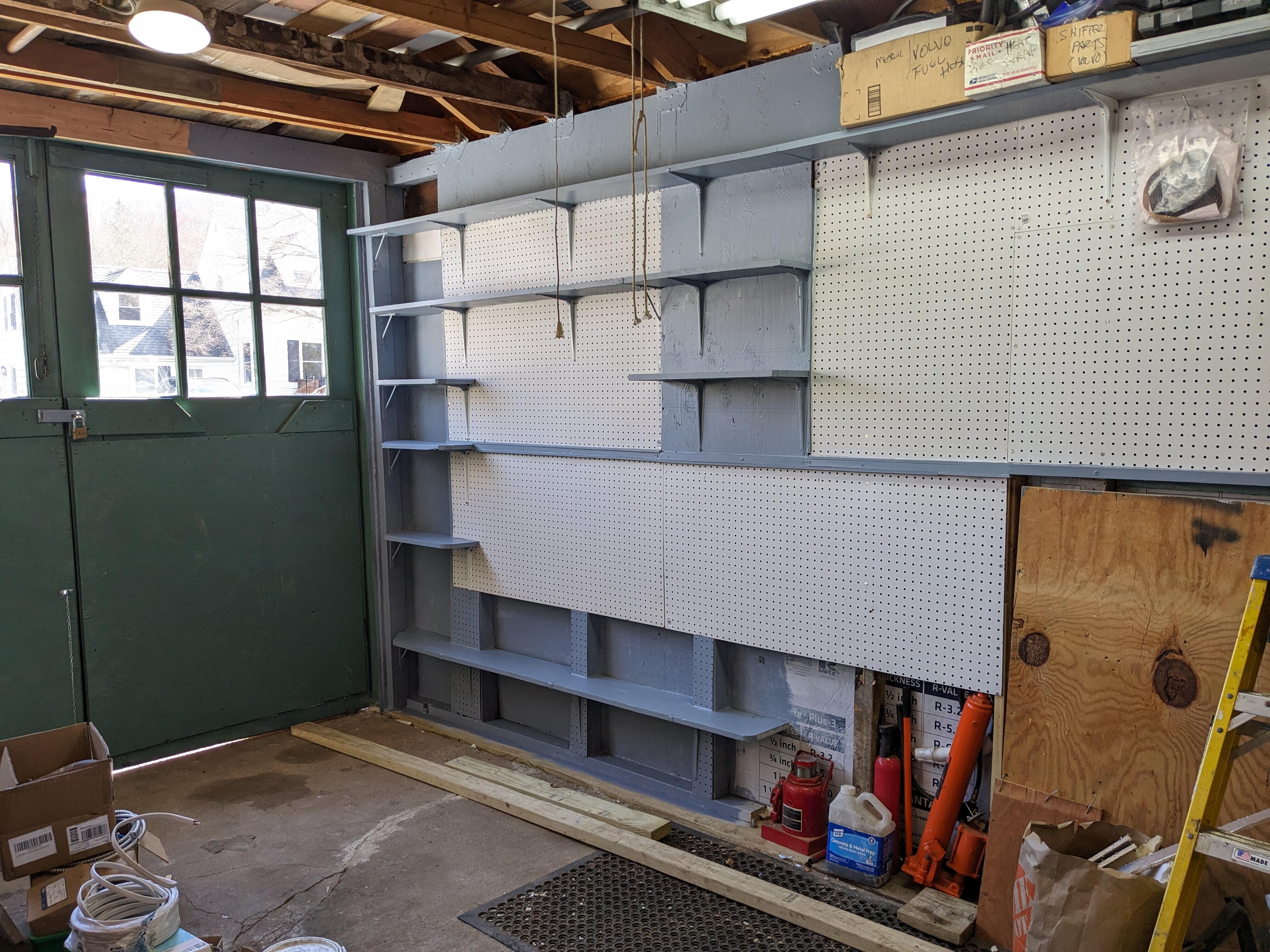
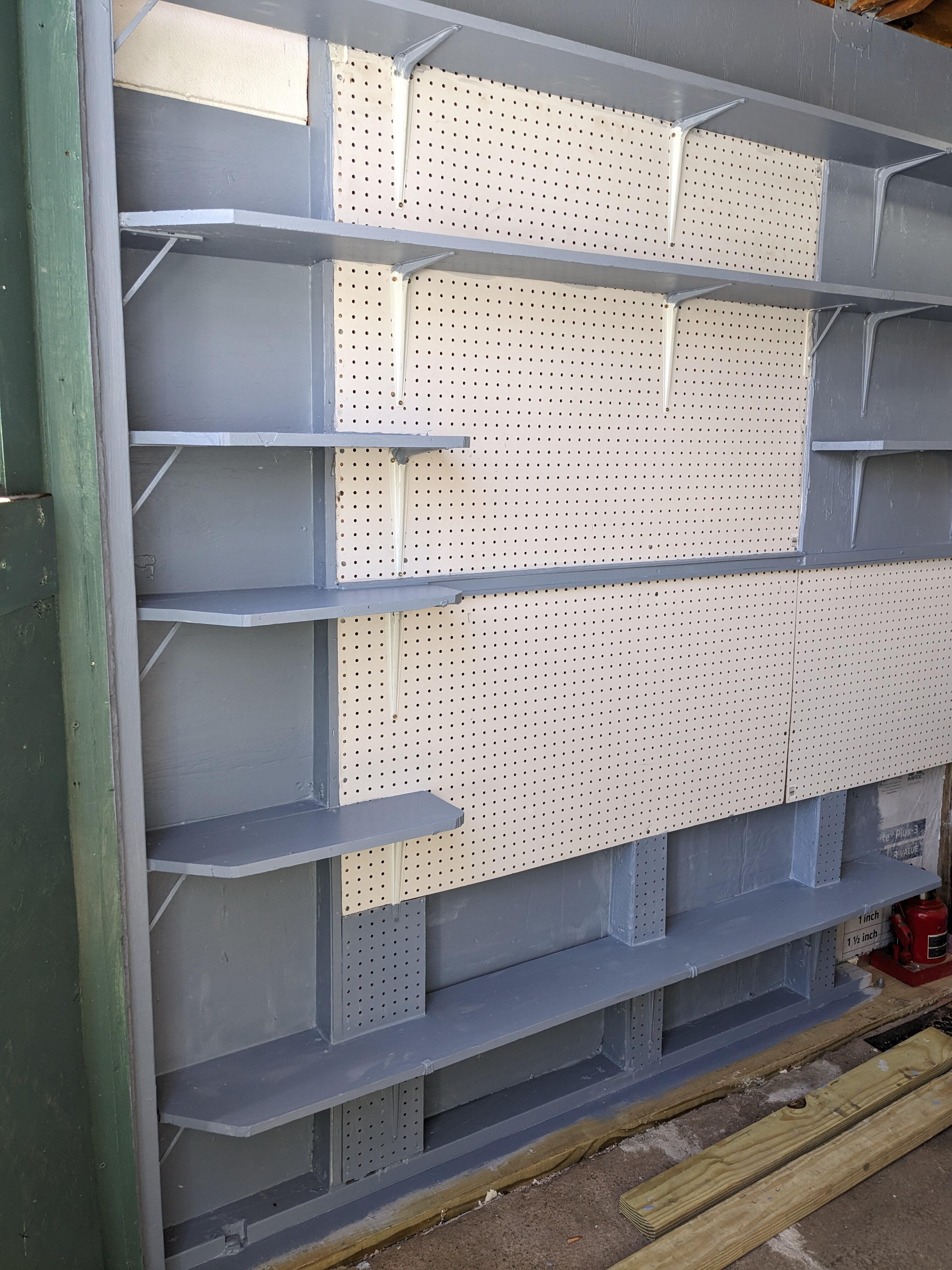
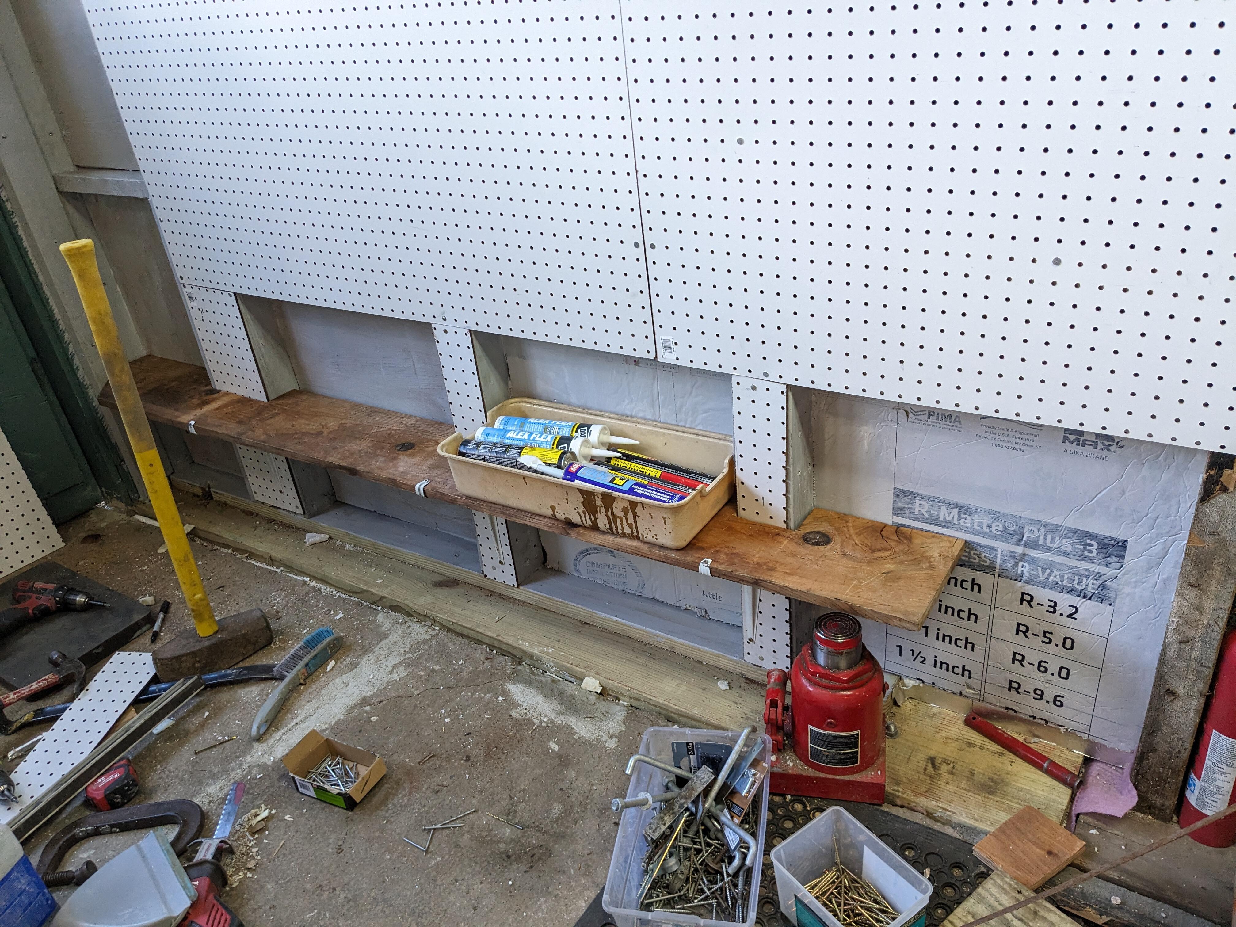
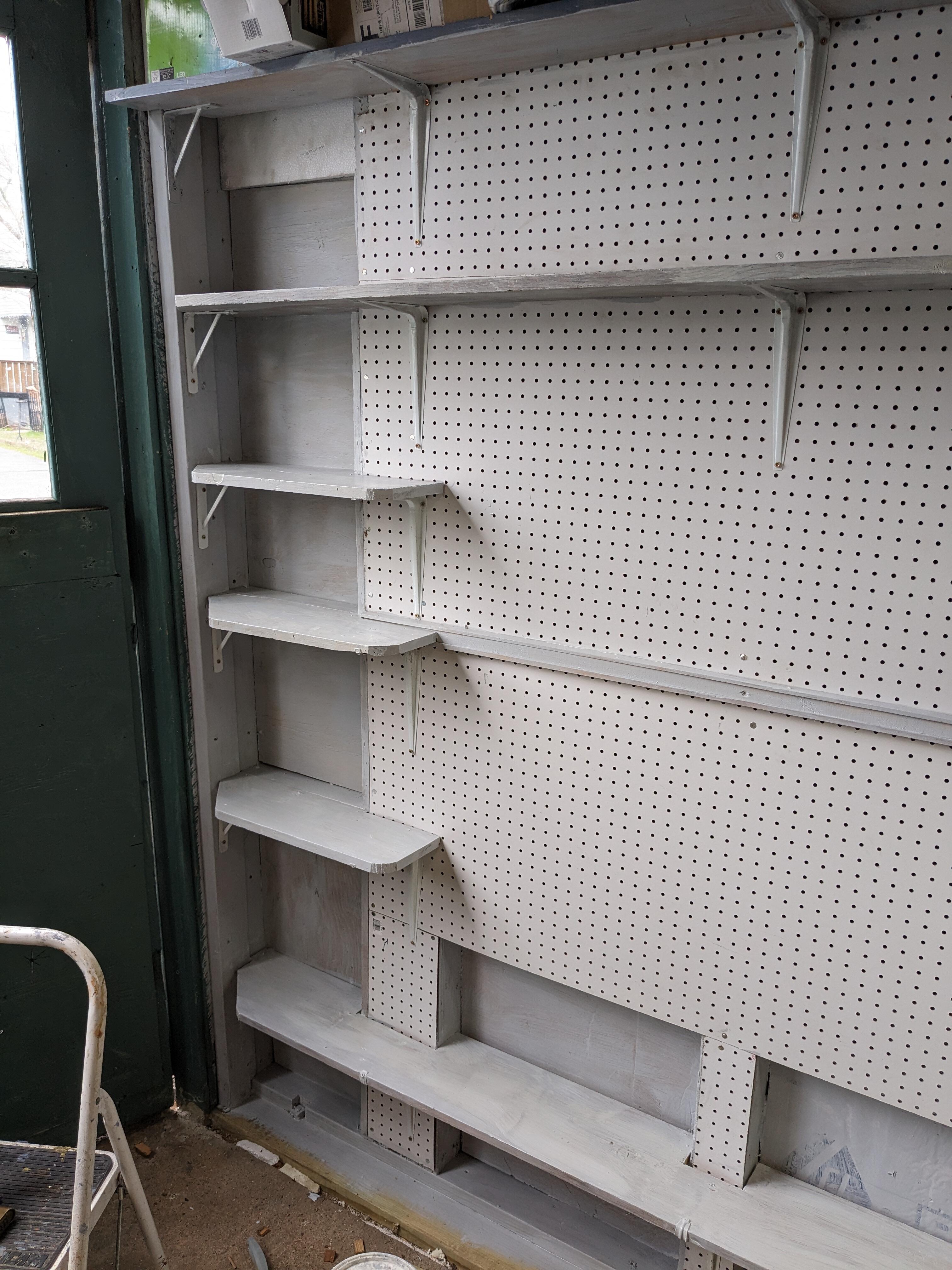
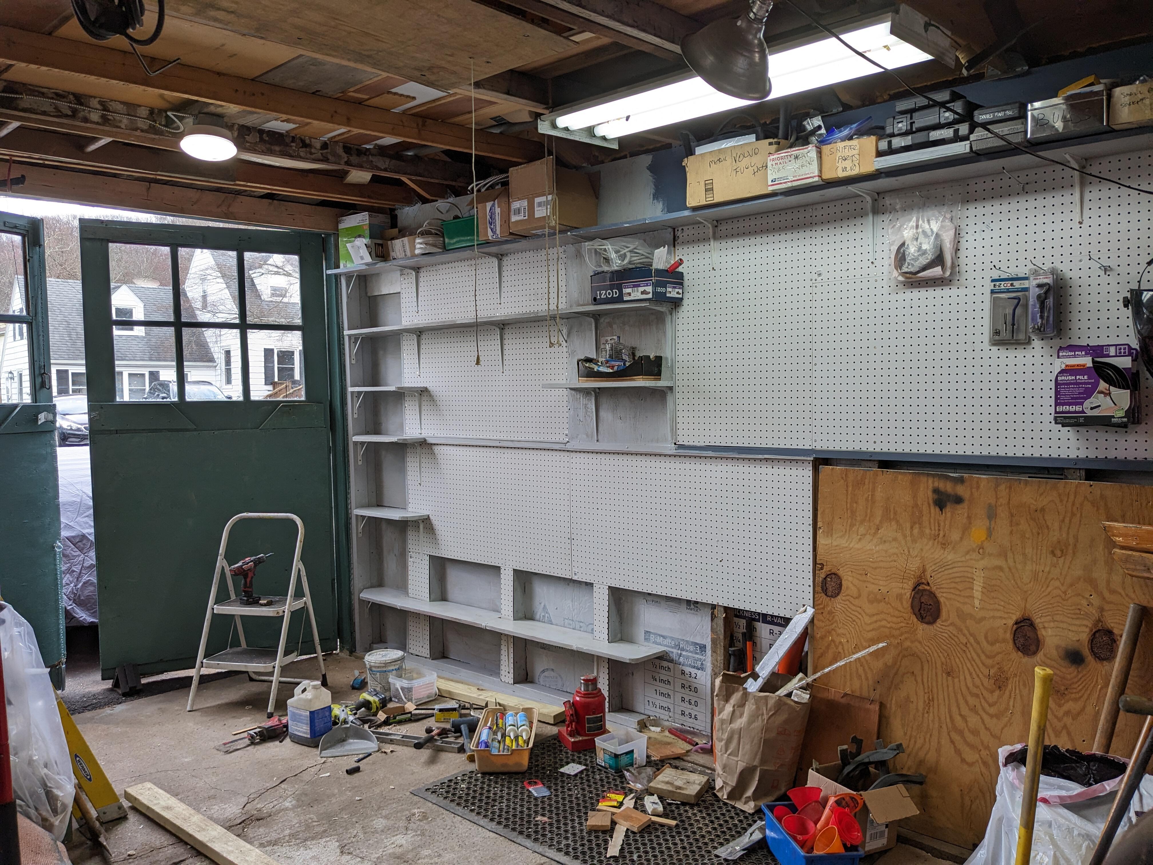
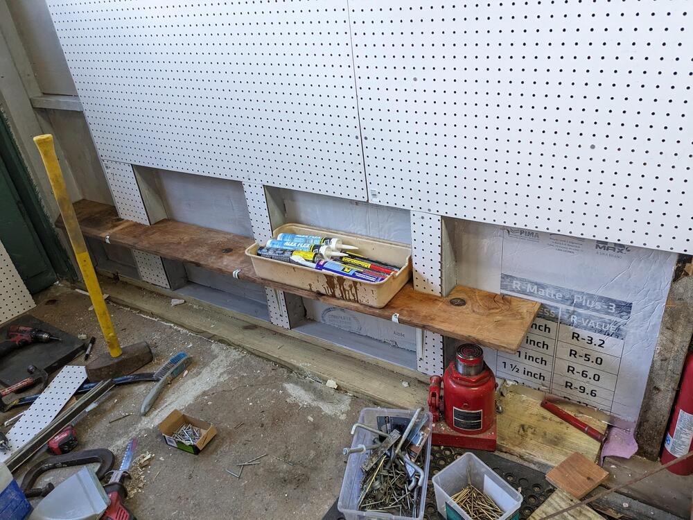
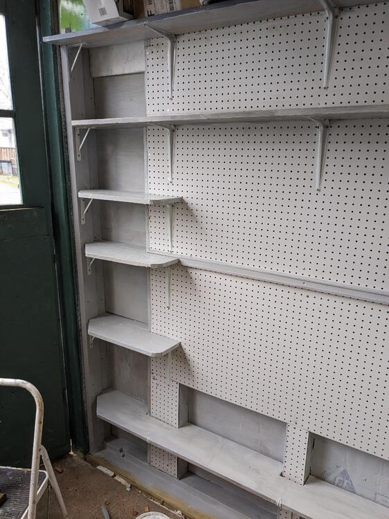
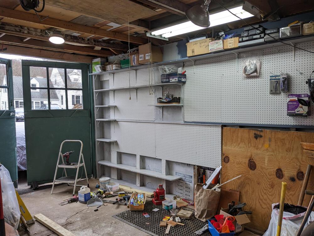
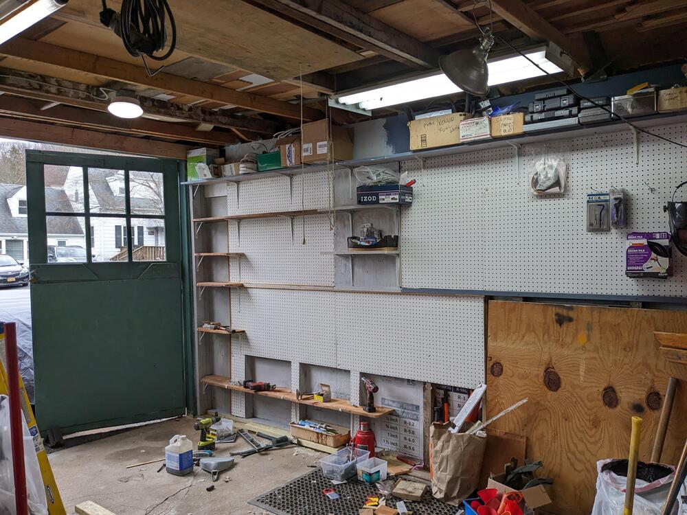
Small stuff in the garage. Trying to figure out what I wanted with the forward lower half of the (repaired area) south wall I decided to pegboard down to about 2', then I'm adding another 2x4 plate on the bottom to make a raised "shelf" - I need a place to store heavier odds and ends that I keep in these plastic bins. This will work out fine. The shelf is total of 8" depth, so doesn't extend in beyond the sill plate After I added the 2nd from the top 8" deep x 63" shelf, l added some more 7.5" x 22" corner shelves - I've set sheathing on top of the 1-in insulation, in between the studs, so I can use the maximum depth for the shelves (added approx 3" additional in the recess). I decided I didn't want any additional full width shelves, trying to keep this wall as open as possible. Had time to prime. I can't do anything with the other half of the lower wall, until I address the sill in that area. So that's going to just stay the way it is for the time being.
-
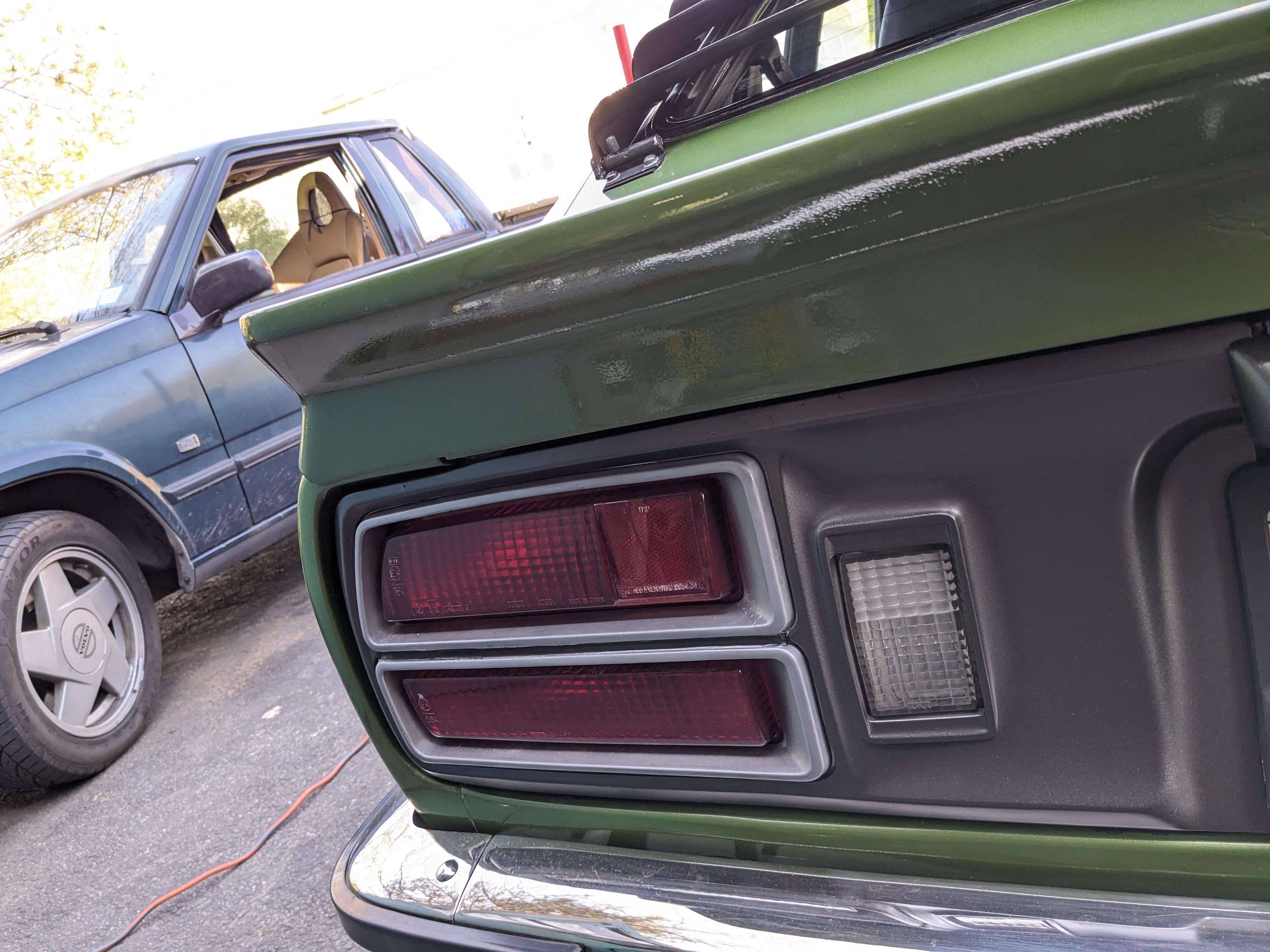
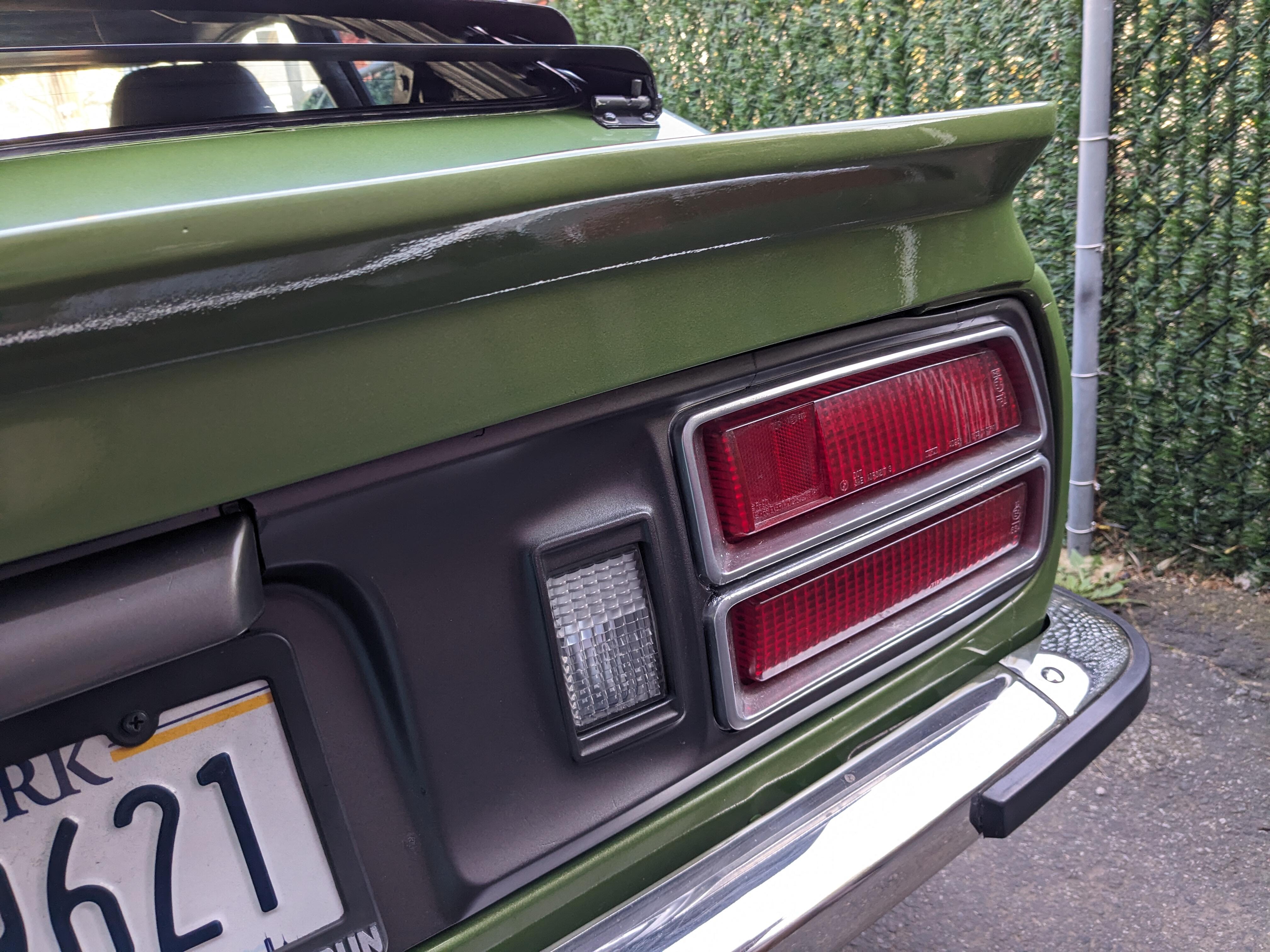
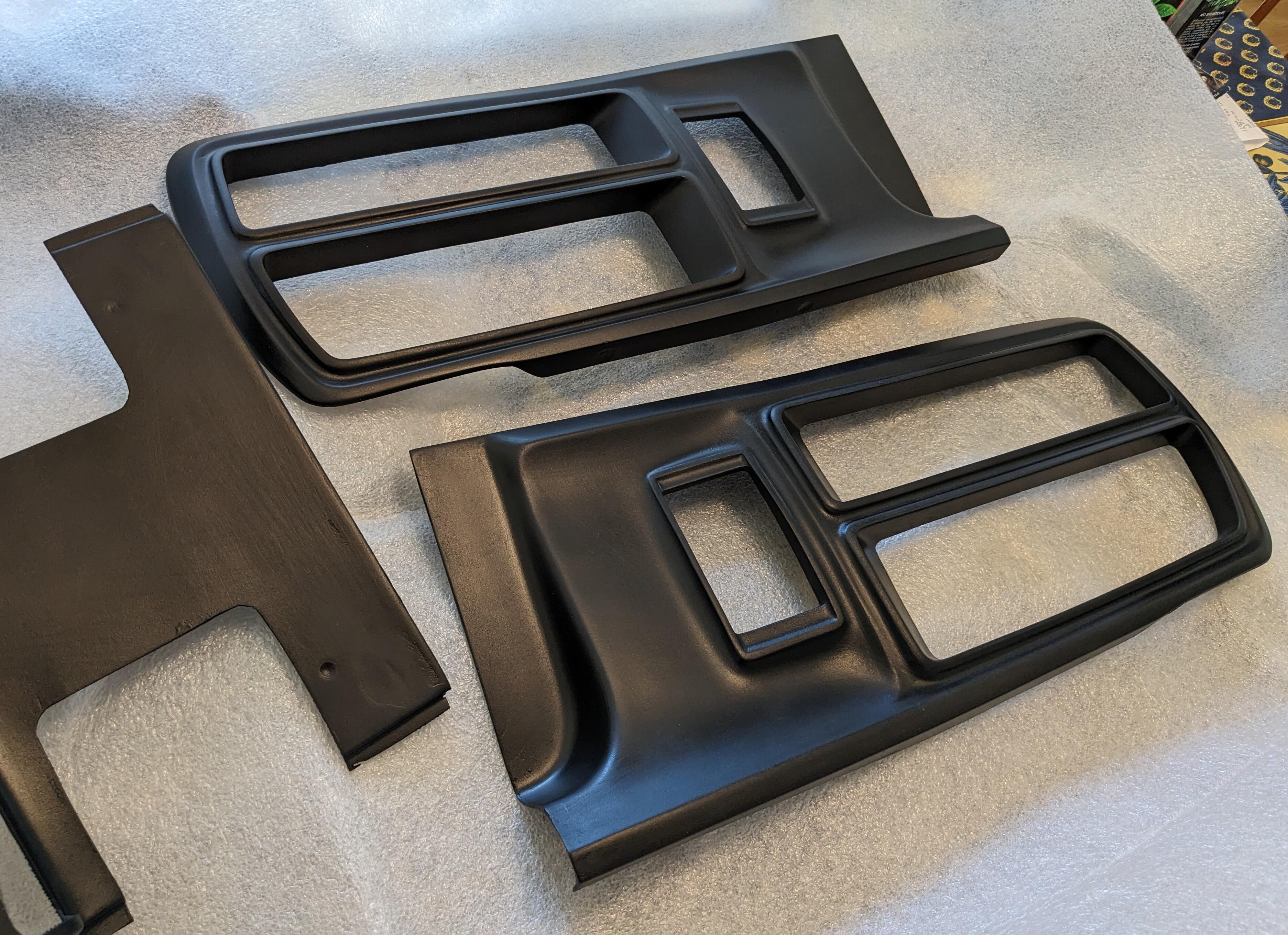
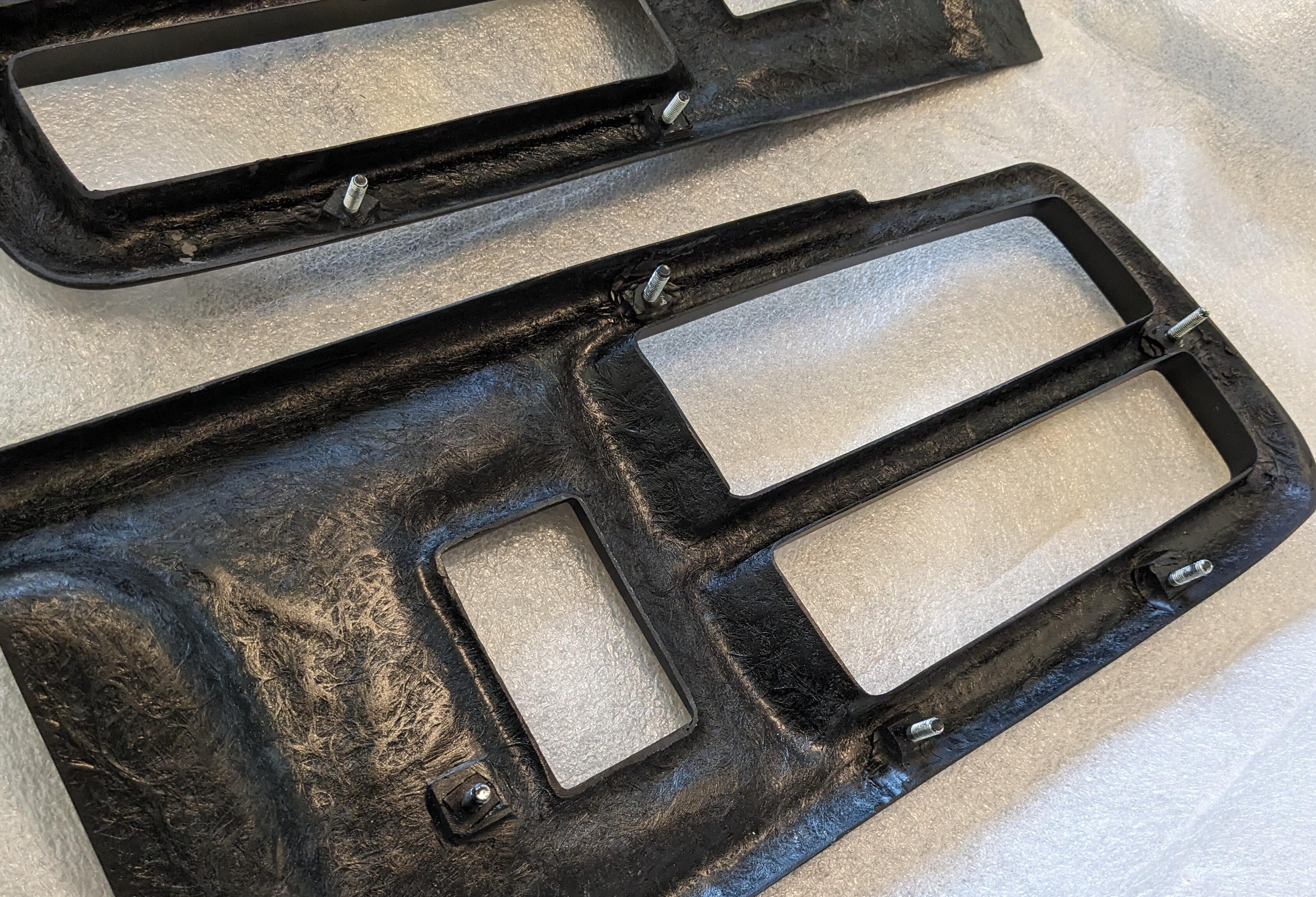
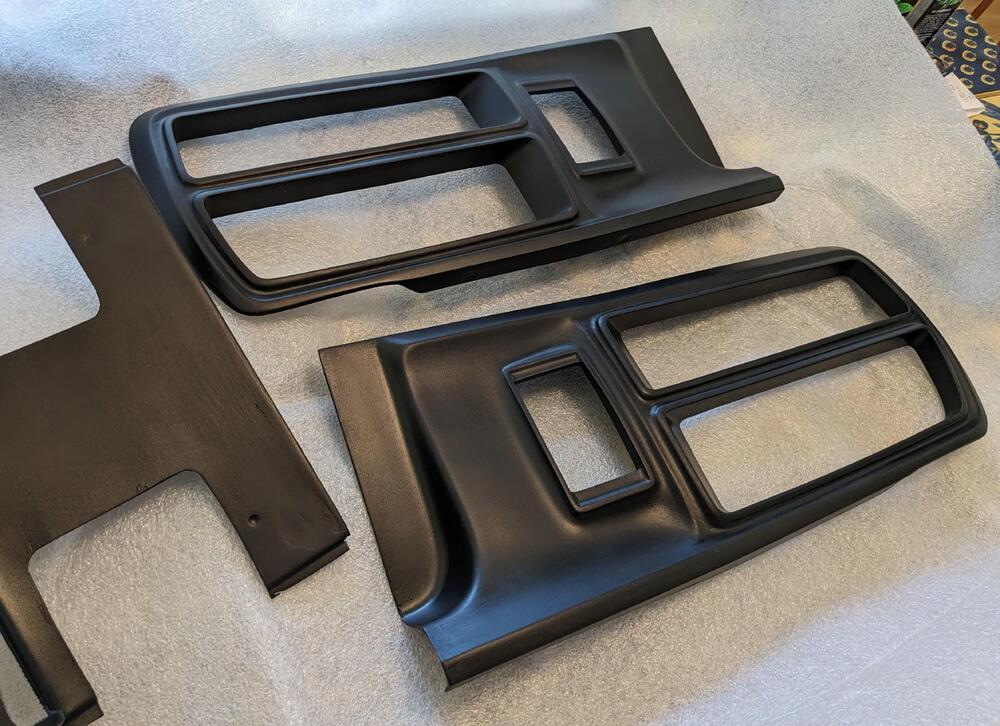
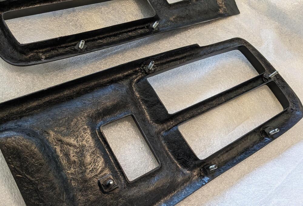
Fibreglass tail panels finally came - I placed the order in mid November with Zociety - I was getting worried that they were a scam. Oscar did communicate a couple times, but he always implied shipping was just around the corner. Anyway, he was very apologetic at the end there, and said that if I were to buy something else in the website they would give me a break. They appear solid enough. I went for the plain fiberglass finish. I have to paint them anyway & want the chrome edge, which they do not offer as a finish
-
Looking a little further online for GM 80's versions - there is this brand new old stock one which certainly could be adapted. It has 2 diaphragms instead of one eBay listing