


Dave WM
Free Member
-
Joined
-
Last visited
Everything posted by Dave WM
-
 looks like part of the BCDD system, used to know when going over 10 mph. "amplifier"
 -
how close to Blairsville? I am planning a house hunting trip there around the same time as this. Prob be in the suburban, don't think wife is up for house hunting in the Z
-
that is not a normal looking plug. I think you need an EFI system.
-
-
will take one last crack at this. the assumption is the poor engine behavior is fuel related. Further the assumption is the fuel mix is too rich. IF that is the case the new spark plug test could quickly confirm. The problem with the assumption is lack of black smoke noticed in the video tends to point away from a rich mix. But again you may have issues with correct readings. The gauge could be incorrect, the video lighting may not show smoke. Test equipment must be tested to make sure its accurate before completely trusting the readings. IF the new spark plug test confirms the condition is overly rich, then the indicated too high a fuel pressure can be part of the problem. If not then you can spend a lot of time chasing the wrong issue. I did not go back and re read everything but if this is the car with the super high compression, then there could be further evidence of long term over rich (and therefore excessive carbon build up on top of the pistons raising the compression ratio). The new spark plug test is super easy to do please try that before continuing to chase any other issues. If they come out black then at least you can be SURE its a fuel mix ratio issue. I invested in a "color tune" clear plug just so I could see the combustion process when I was trying to diagnosis a lean misfire at idle. Not saying you need one of those, but if you had one it could substitute for the new plug test. If I was 100% sure its too rich, I would start by substituting a rheostat for the temp sensor (bullet lead to ground thru the rheostat) so I could REDUCE the resistance, which should lean out the ECU. Most of the time I see folks adding resistance to cure a too lean condition, which would be to insert the rheostat in series with the bullet lead. I like your resolve to get to the bottom of it, I am sure you will ultimately be rewarded with a fine running car. I can tell you that when they are sorted they start easy, get good gas mileage, and run great. I just got back from another 800 mile trip with no issues and got about 25mpg going freeway speeds most of the way.
-
oh well a survivor gets the treatment, then goes up in flames. Wonder if it was insured for 80k?
-
outside of toasted wires, seem like the only difficult part would be how to address the commutator, if its scored up it would be an issue. I recall working on small electric motors for RC cars and Planes they were brushed with segmented comms (DC motors) and it was common practice to use a small lathe to dress copper. I assume that would be a good idea with the solid comms on alternators, but you would need a full size lathe to do it right. Suppose you could just spin it and try some kind of abrasive cloth but the idea was to get the comm true so it would make full contact with the brushes. would be interesting to take a reman apart and examine that area.
-
-
sorry kind of lost, are you getting 36psi with engine off (pump on), are you getting 30psi with engine on and measured vacuum at about 17inhg? If so I would install a new set of plugs go drive it 5-10 miles and then look at them. should be nearly white. Not a fan of trying after market parts if you are having a problem. the OE stuff should work fine. Assuming other stuff has been covered, like air filter as an example. Might want to step back and re check some of the earlier stuff. really need to figure out one thing at a time, if fuel pressure is off, no reason to go further until you have that worked out. There has to be a reason if its not right. re pump swaps, I had an aftermarket style pump that would do 90psi, car ran fine, I replace it with an OE style pump that has a built in limiter (think its 40psi, but not sure). I did it since I like OE stuff, it made NO difference in the performance of the car. So from that I gather the pump would not be an issue.
-
did you test the voltage at the battery with the engine off and then again with the engine running? nevermind I just watched the video. could be the alt or the voltage regulator. Maybe even the battery was damaged.
-
update, got it to under .5 ohms per inch with the 3rd coat. Will let it cure overnite for some durability testing. I keep getting better at the application (practice makes better). The plan is to pull the hatch off, leave the glass in, set it upside down and do them all over a weekend. While I have it out I will finally get to install the outer hatch weather strip.
-
Technique seems to be key, one path is much lower in resistance, sure it has to do with application thickness. Just getting the right technique to apply a thick enough trace that does not tear up when removing the masking seems key. I suspect it will come down to multiply thin coats, PITA but that maybe what it takes. Frog tape is working well. I just laid down a second coat to one of my better lines. My goal is about .5 ohms per inch. that would be about 10 amps, 120 watts. Just a guess but maybe that would be enough. Need to go check that fuse rating. One other thing I noticed, the second coat seems to go down easier over the existing dried coat. With raw glass it can wipe off with the brush leaving a bare spot so have to be extra careful on the 1st pass.
-
hope so, made a few more test lines, I tested it, looks like its about 5 ohms per inch, so will have to go measure the grid and see what that works out to be. Will also see if that changes after it cures overnite. if that's the case, then 36" wide times 5=180 ohms,/16 grids +11ohms=about 1 amp, not enough to generate any real heat (12-13 watts max). I will check the resistance again after it cures, and see if adding another layer of paint will get it down to a lower number. just a guess but I would think 1ohm per inch would get to about 65 watts, at about 5 amps, which I think is prob about 1/2 of what it should be when you consider it used a relay to control the current and not just a switch. I don't recall the fuse size but if it was a 10amp then again guessing 5amp would be a target amount if it had a 20amp then they prob wanted 10amp or about 120watts. to get that I would need about .5 ohm per inch. One thing for sure, the copper lines sure are purdy!
-
got the caswell stuff in. Seems like its very conductive, I had some issues with bleeding under the masking tape, switch to some green "frog" masking tape which worked much better. Did several tries to see if I could figure out the best technique. Has to be peeled off while wet or the copper trace will just pull up with the tape. Trying different brushes and application thickness to see what works best. will get some pics posted up tomorrow, but so far so good. I don't think it will be very durable, as you can easily scratch off a line. Perhaps it will be a bit more sturdy when painted over the remnants of the old so as to have something to "bite" into.
-
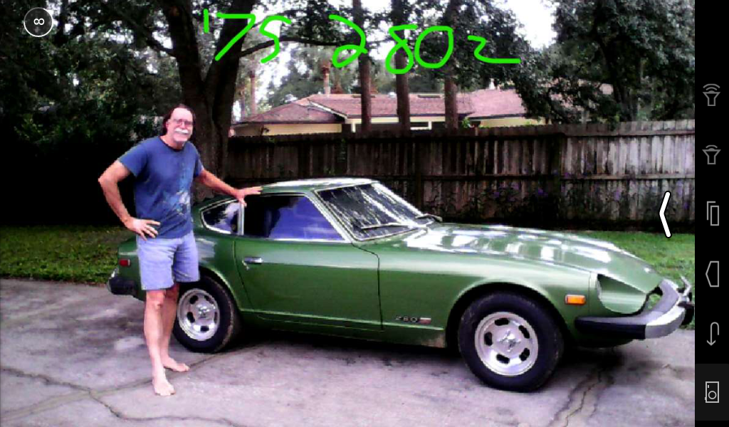
I would say you are not likely to find a no rust Z for anywhere near that. Keep you eyes open. I would say you are looking at a min of 7-8k for a late model S30 and that would be a deal. You would be better off getting about 10-15k and getting one that is in really good shape.
-
It would seem the amp meter would not reflect the current draw of the headlights, if that matters, with the power coming directly off the battery post. I can't recall how hard it would be to tap into the shunt to make the amp meter function like it should.
-
I went ahead and popped for the caswell copper paint (4oz), 50$ shipped, if that does not work then I don't think I could justify the expense of the other compounds out there just too expensive for a full grid replacement.
-
I will do some more searching, its not too much and would be good to know if it would work at all. If you can get a really fine line like using a pin stripe brush, prob could keep the waste to a minimum. I think as an experiment I will see how far I can get with a 1/2 oz bottle of model paint just to get an idea of that. I guess this is why they only sell it as a fix for small breaks. too expensive to attempt a whole grid. Anyway will still see how far I can get with the model paint.
-
MSA or zcar depot will have, they are color coded for amperage. the main thing is they do not flame up when the burn out. So you cant really tell if they are bad by looking at them. the colors maybe on the plastic caps I don't remember. but if not pretty sure the FSM cover the color code as well.
-
think I will try this one, like the idea of brushing on to build up a thicker layer quicker, and used for track repair (assuming that means PC board tracks) would have to be very conductive. https://www.etsy.com/listing/519528043/silver-conductive-paint-scp?gpla=1&gao=1&&utm_source=google&utm_medium=cpc&utm_campaign=shopping_us_b-electronics_and_accessories-other&utm_custom1=b66cd0c9-ee2b-42c1-98c1-4d27634cbc4f&gclid=Cj0KCQjwz93cBRCrARIsAEFbWsgTmeVGslyQpamHc6pYAtTZE6mN0NNWoSss2Gc1j9cY4iEpD2s0GgMaAjsIEALw_wcB oops, yikes think its like 15gm, going to have to do some more research.
-
indeed it really bugs me when things don't work as they should.
-
big fail #1 about 2 meg over about 2 feet, clearly not conductive enough. Guess I should have figured that, don't think graphite is a very good conductor, couple that with thin line an very thin deposit... I will look into those other products. I was encouraged by how nice a line I was able to get. I googled to see if anyone had tried to reproduce an entire grid, but could only find the small fixes for breaks OR the complete grid that is solid looking copper strips that have to connected in series to prevent too much current. Seems like the best way IF a good conductor can be found, would be to have a stencil made up, position it and then shoot the whole thing in one pass.
-
some good looking products on those links. I just tried it out on a piece of plate glass, approx. the width of the hatch with some of my "slip plate graphite coating". I am sure its not a good choice but since I had it on hand figured why not. If nothing else it will be one of the many products to test. should be interesting to see the resistance reading. Left a nice black line. The masking was pretty easy, with the grid as a guide I suspect it will be very easy. have to let it dry, so maybe a few hours from now I can give a report back. should be able to compute the amount of resistance of a single line, the multiply by number of lines to come up with a resistance reading to do some current/wattage read out. have no idea of what it should be but figure 10-20 watt would be good, so lets make it easy 12 watts would be 1 amp at 12v. guessing they are about 1" apart and say about 2 feet so about 25 grid lines. I=E/R so 1amp=12v/12ohms, 12*25=300 ohms per line (300ohm in P would be 12ohms total). so as a target assuming I have the right number of lines, I am shooting for 300-150 ohms per line. that would give me 12-24 total watts. Of course I have no idea if the required wattage is right. Suppose I could go measure the current thru another car with a working defrost, just to see if I am in the ball park Think I did that right.
-
oh and I have some spray graphite I used for dag on old CRT's I may try and see how fine a line I can make on some plate glass just to see how it would work (spray on covering with masked off lines).
-
I have about 2k ohm resistance and no heat being generated (a few ma at best flow). Don't like the idea of a grid replacement kit that sticks on, and the minute amounts of conductive repair kit only allow for a very limited fix. With my VOM is seems like most of the grids are simply non conductive even though they seem intact. I was thinking of using an air brush and masking tape to mask off and reapply some kind of conductive paint. see link for a decent amount of paint to work with. https://www.amazon.com/Caswell-Copper-Conductive-Paint-4oz/dp/B00A6FO6G8/ref=sr_1_1?ie=UTF8&qid=1536694226&sr=8-1&keywords=caswell+copper+conductive+paint I was hoping that copper head gasket seal may have had real copper in it but from what I have read it is color only, non conductive.

