EuroDat
Community Member
-
Joined
-
Last visited
Everything posted by EuroDat
-
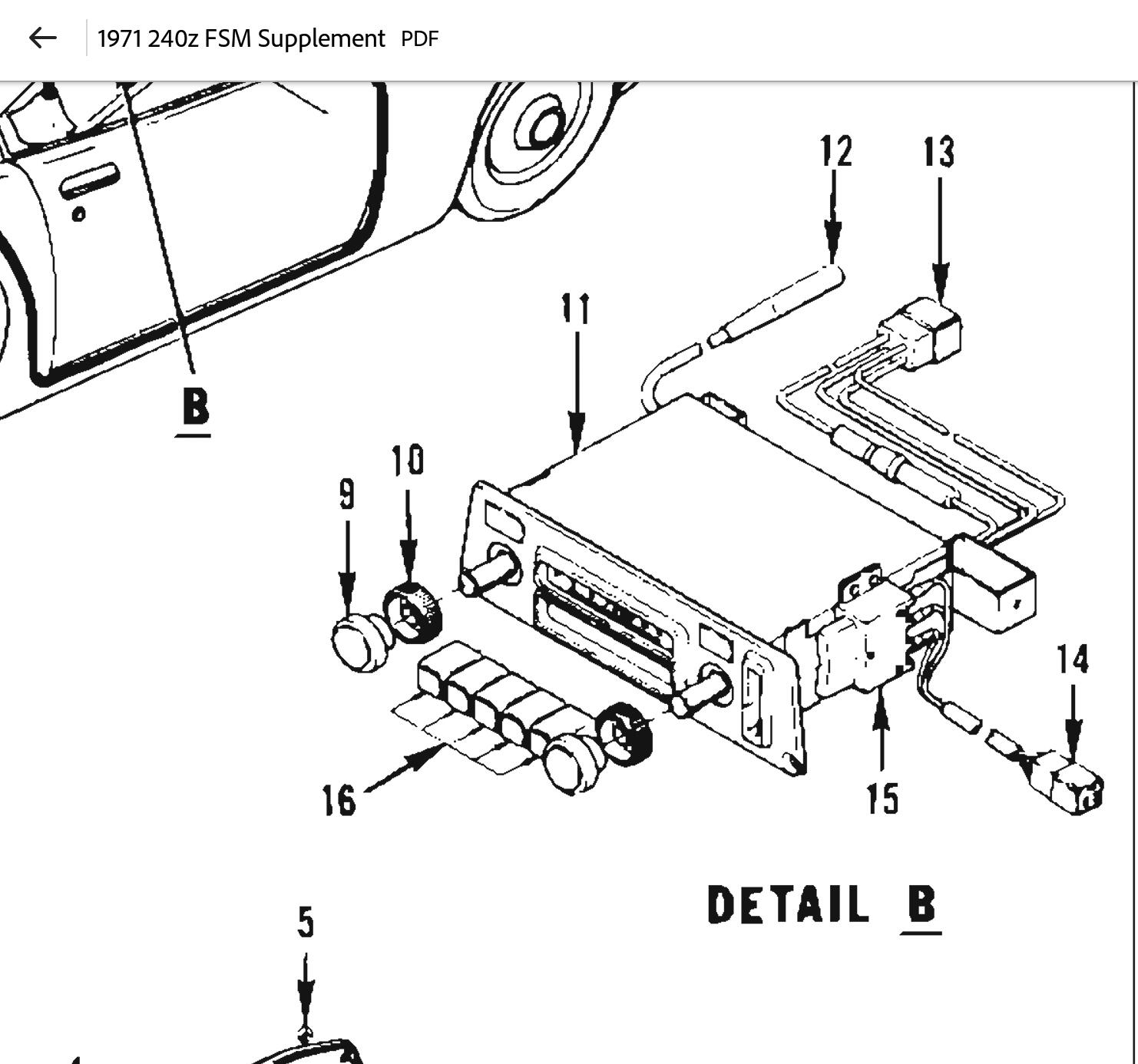
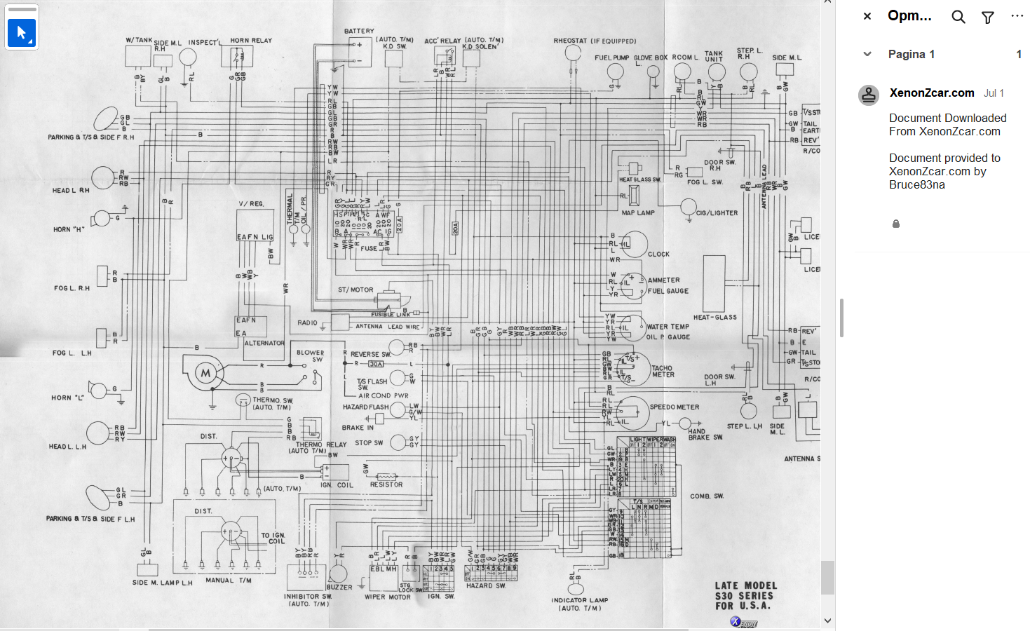
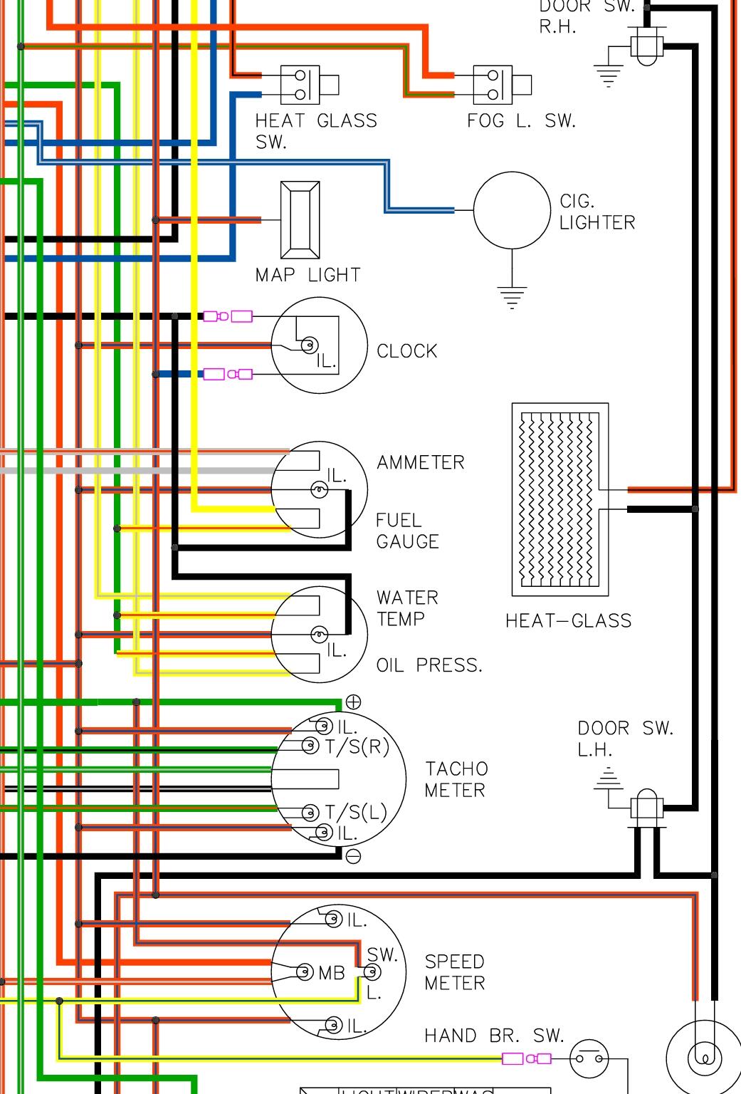
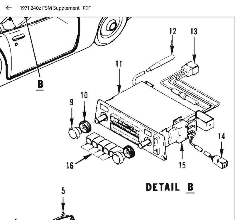
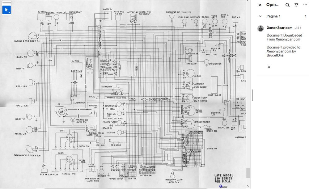
Evreything I find on the internet (ignoring the BS E-bay ads quoting antenna switches to suit datsun 240z to 280zx) seems to point to that type. The wiring diagram is based on the two diagrams in the Xenon website 1971 240z FSM supplement In the detail Pos 14 & 15 seem to match.

-
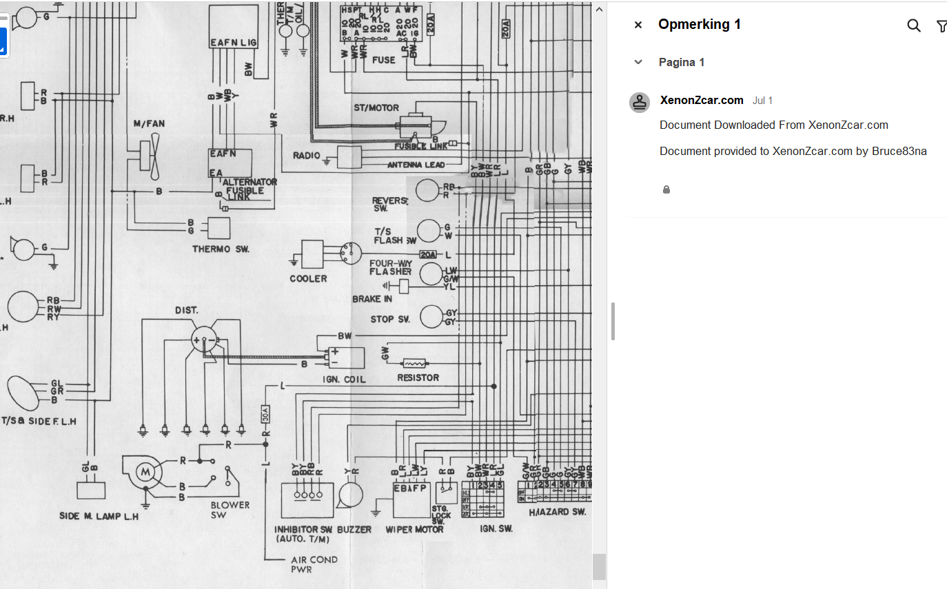
I see the Cooler is gone in the late model 1971 FSM Supplement
-
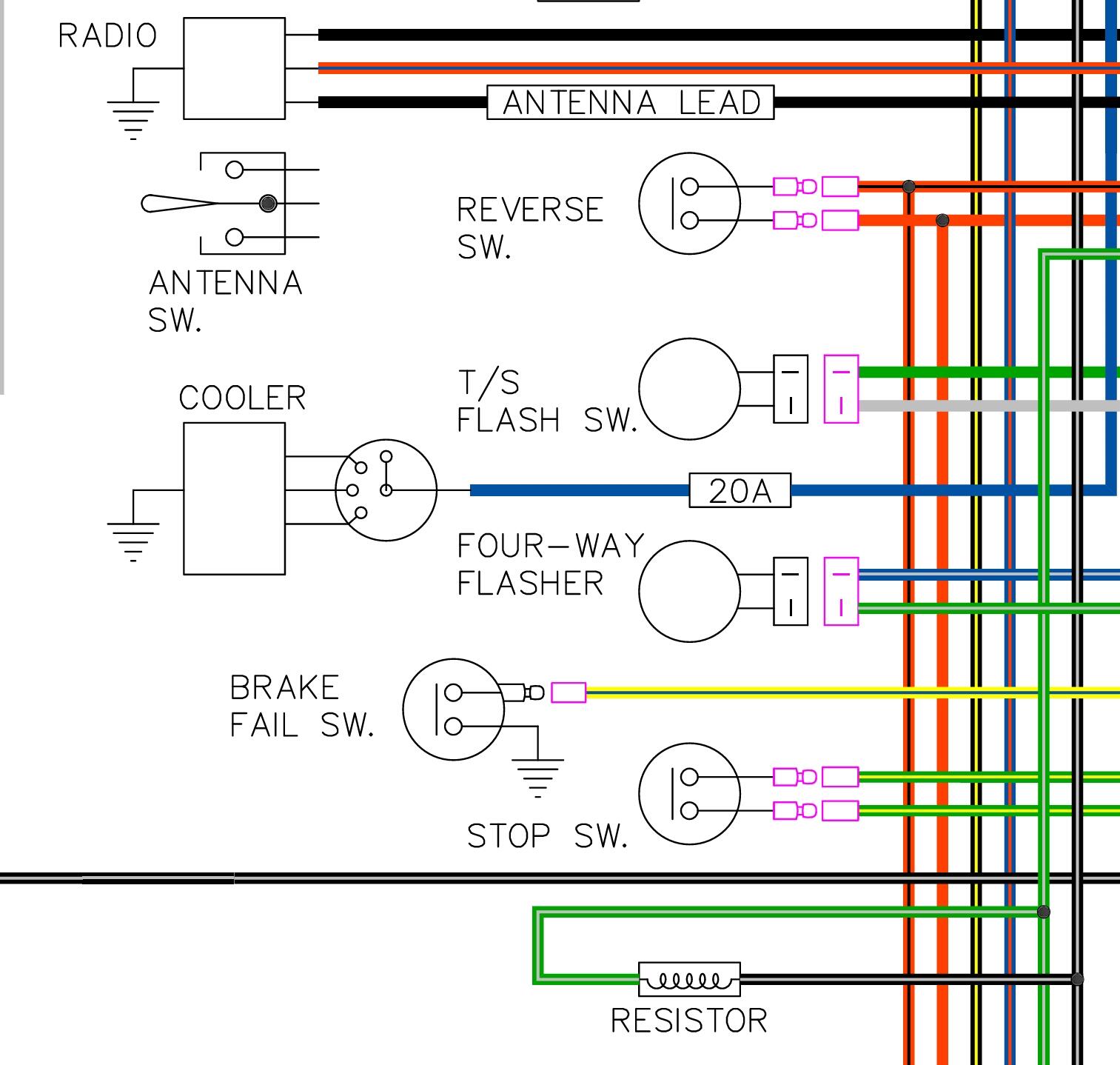
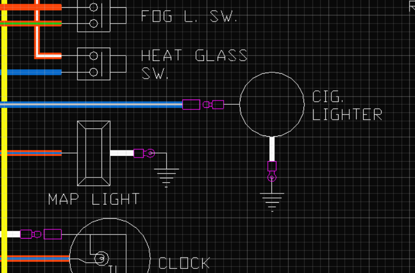
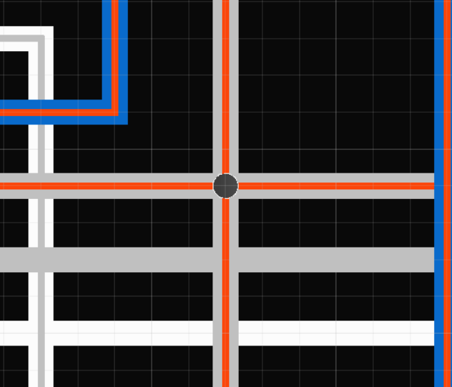
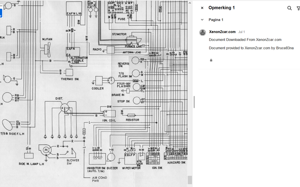
Hi Captain, You have an good eye for detail.😀 I'm not sue if the Map light uses a bullet connector of spade for the power supply? The blower is in the cabin and I think the Cooler is the engine fan maybe? , but I must admit I have never seen an original 240Z with original air-con fitted --> Thr blue branch off wire. The was from a source file I used from XenonZcar 9 years back.
-
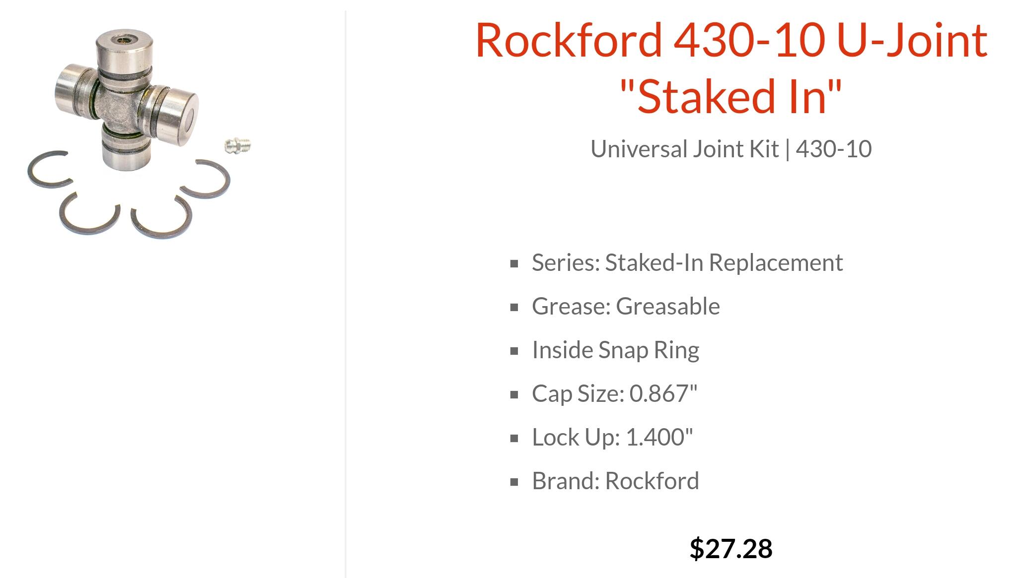
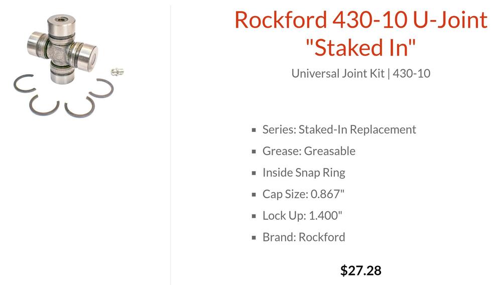
I read the Subaru drive shaft uni-joints were the best replacement for the 280Z and came with inner circlips. Rockford u-joint replacement kit 430-10 "Staked in" replacement. I can't confirm fitment.
-
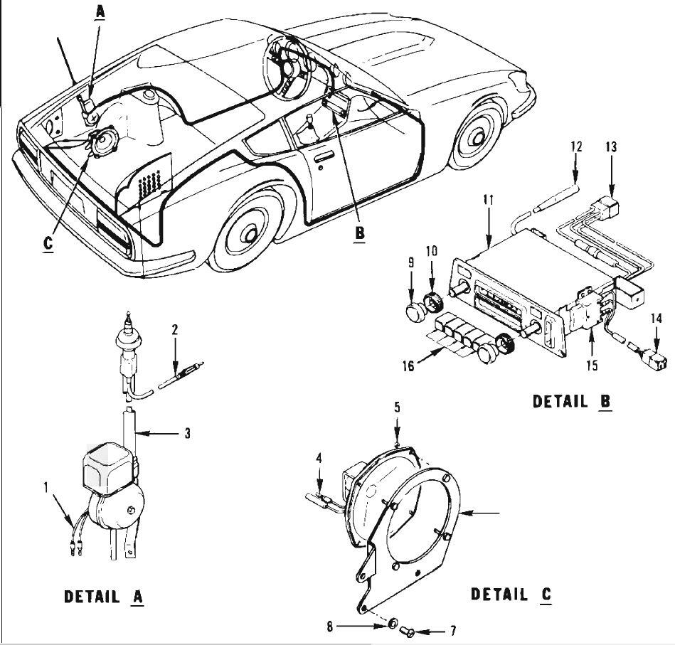
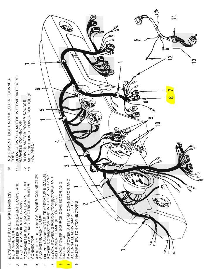
I made a low res print in pdf of this last update Rev1.1 The radio connector is not right. It should be 4 pole. See screen shot of the supplement. Connector Pos:13. I think the speaker wires come from pos 13? ColorWiring240Z1971Early_TerminalBlockExample09-aug-2015 Rev1.1.pdf

-
Ill make a list of things I miss. If anyone has parts handy and can take a photo or even out of memory would be a great help. Please don't hesitate to make or suggest any corrections. Like I mentioned, I don't own a 240Z to fact check any of this.
-
Hi Captain, Communicate mistakes on my diagram or screen shots would be great. Your example is very clear. Thanx I like the early wiring diagrams too. That is why I'm trying to keep it close to the original layout and adding terminals. I also found a dash connector diagram in the 1971 supplement where I can make out the radio connectors. I can't find anything on the Passing relay.
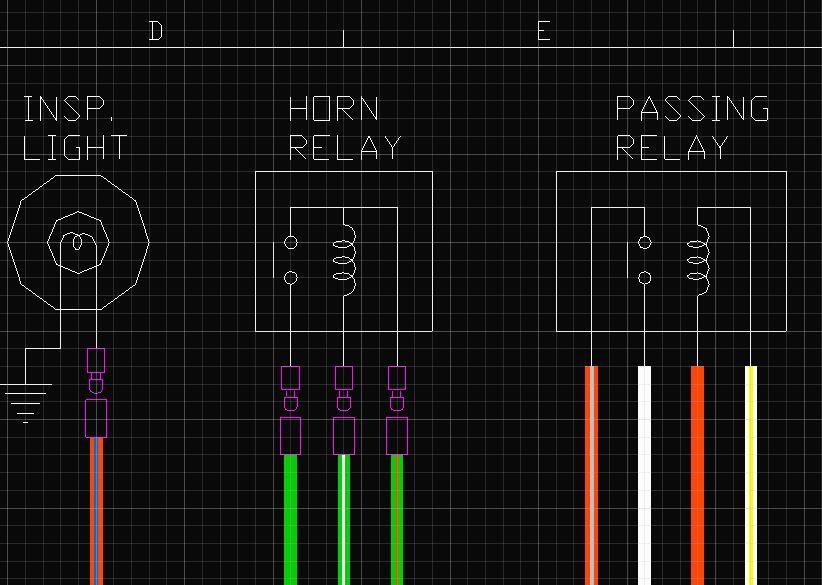
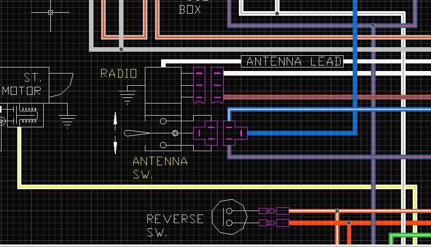

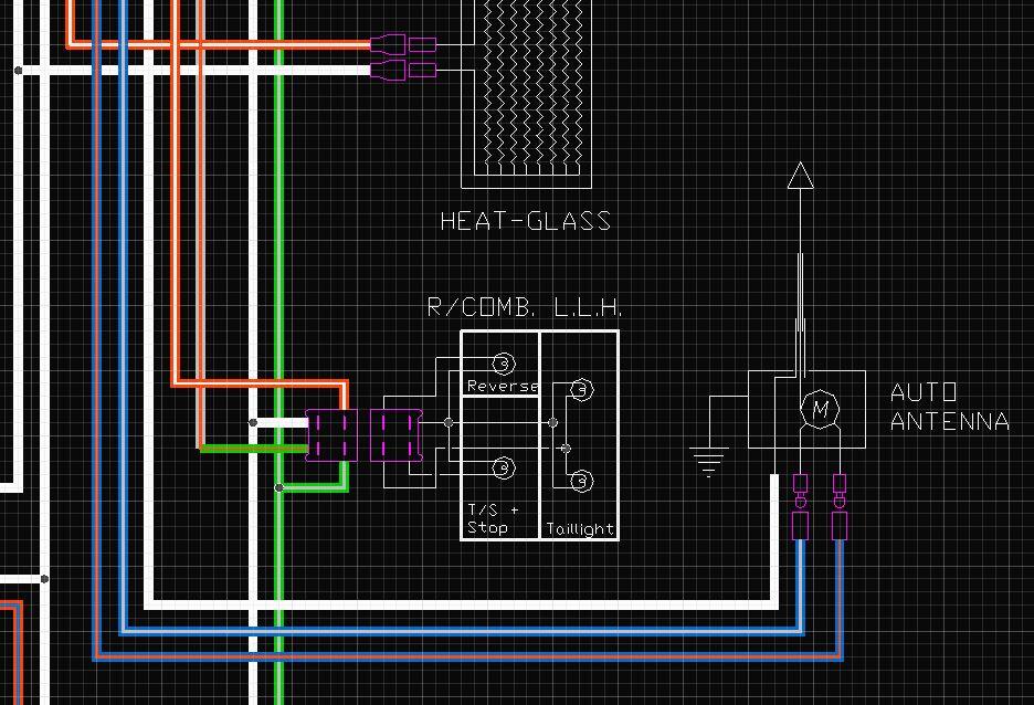
-
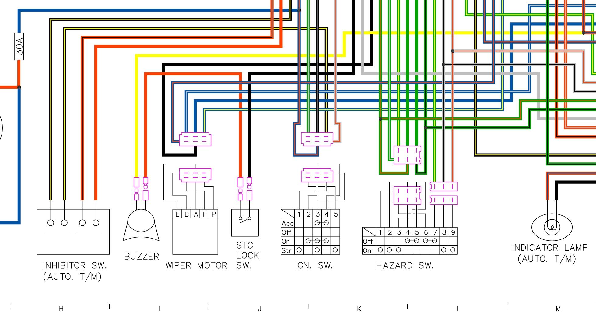
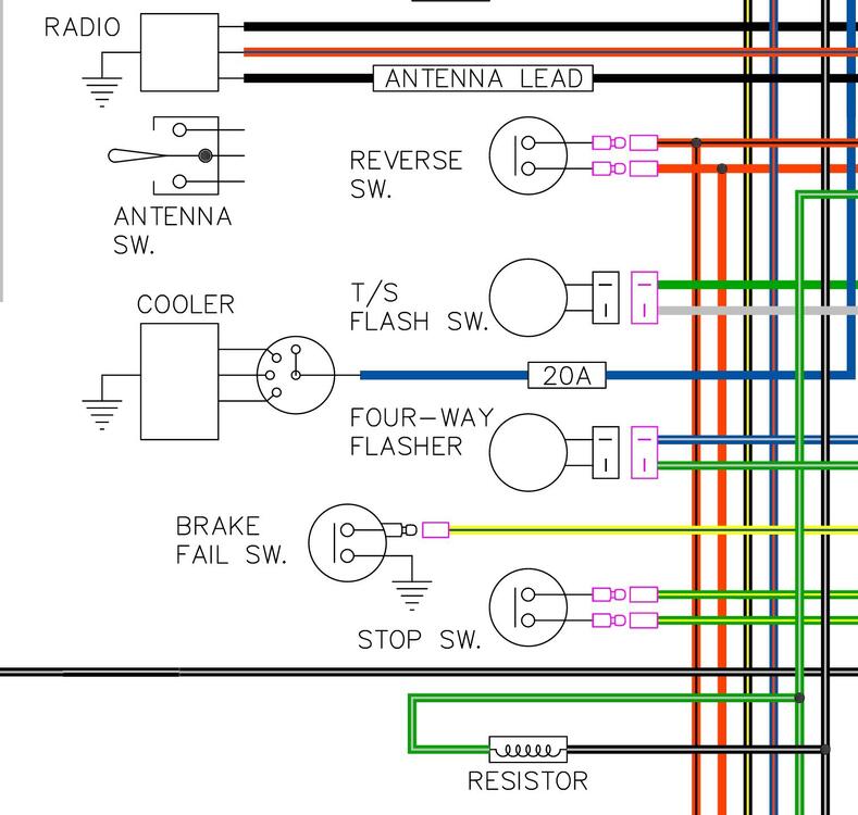
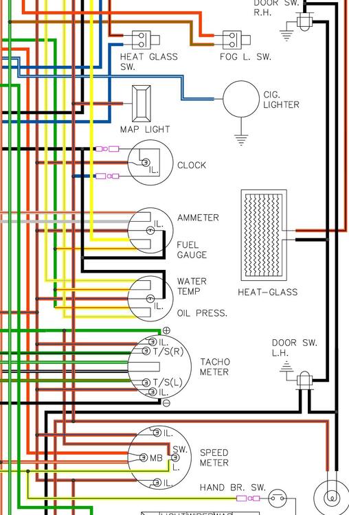
Looking through the drawings to see what I was up too 9 years ago🫣 Most of the terminal layouts are from the service manuals and photo's members posted in threads on this site. I made some screen shots of some of the sections still kissing the terminals. I remember working on the antenna switch, but could not find a photo of its terminal block. I think I'll first update the schema with the remarks from @Namerow and @Captain Obvious b

-
Hi all, Just searching through my drawings on the 240Z wiring diagrams. I was buzy adding terminal blocks te the early 71. It also needs some update "thanks to @Namerow for his input back them" I was too slack to finish it. I could work on the "Terminal block version", but I would need help from you guys since I don't own a 240Z and like mentioned in the thread, the manuals have their issues. Here is where it was in 2015. I also had a request to add Line colour text for people that are colour blind. It's all possible, but I don't want to waste my time if no one is interested. My absence in the last 12 months is due to health issues in the family. ColorWiring240Z1971Early_TerminalBlockExample09-mar-2015.pdf
-
Hi guys, Just quickly dropping in to let you know, I'm still around. I'll read through the thread in more detail later the weekend.
-
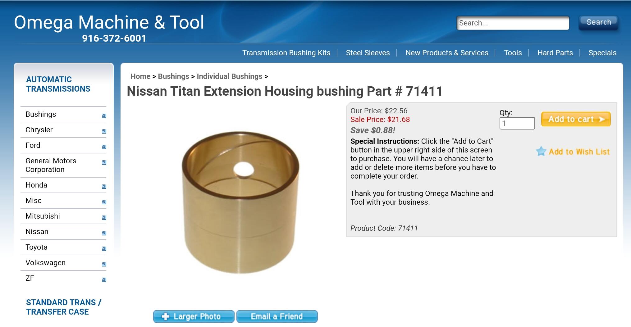
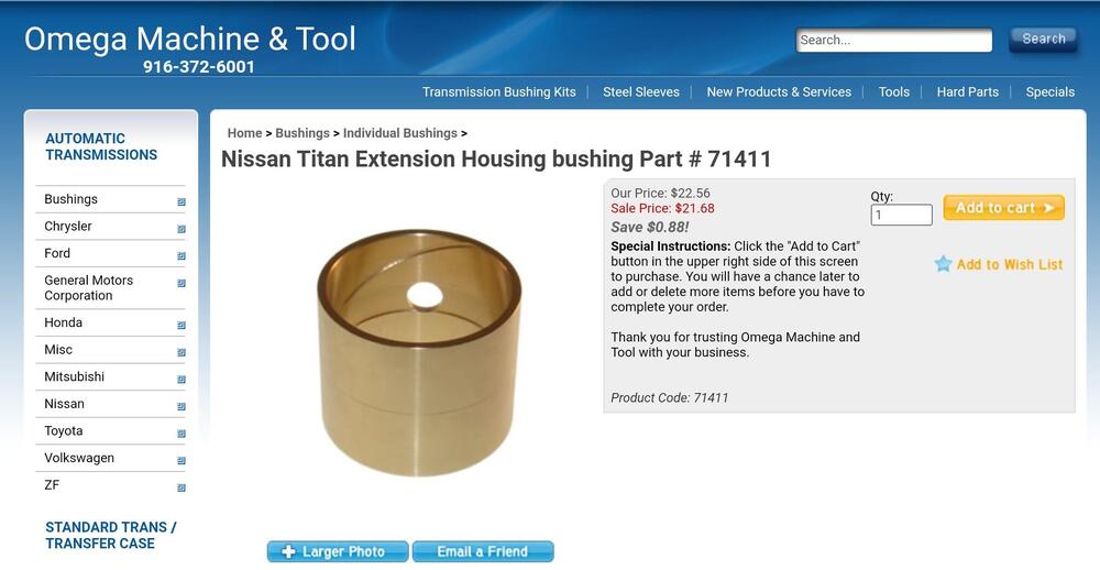
I see thet Omega Machine & Tool know call is a replacement for the nissan titan (FS5W71C)
-
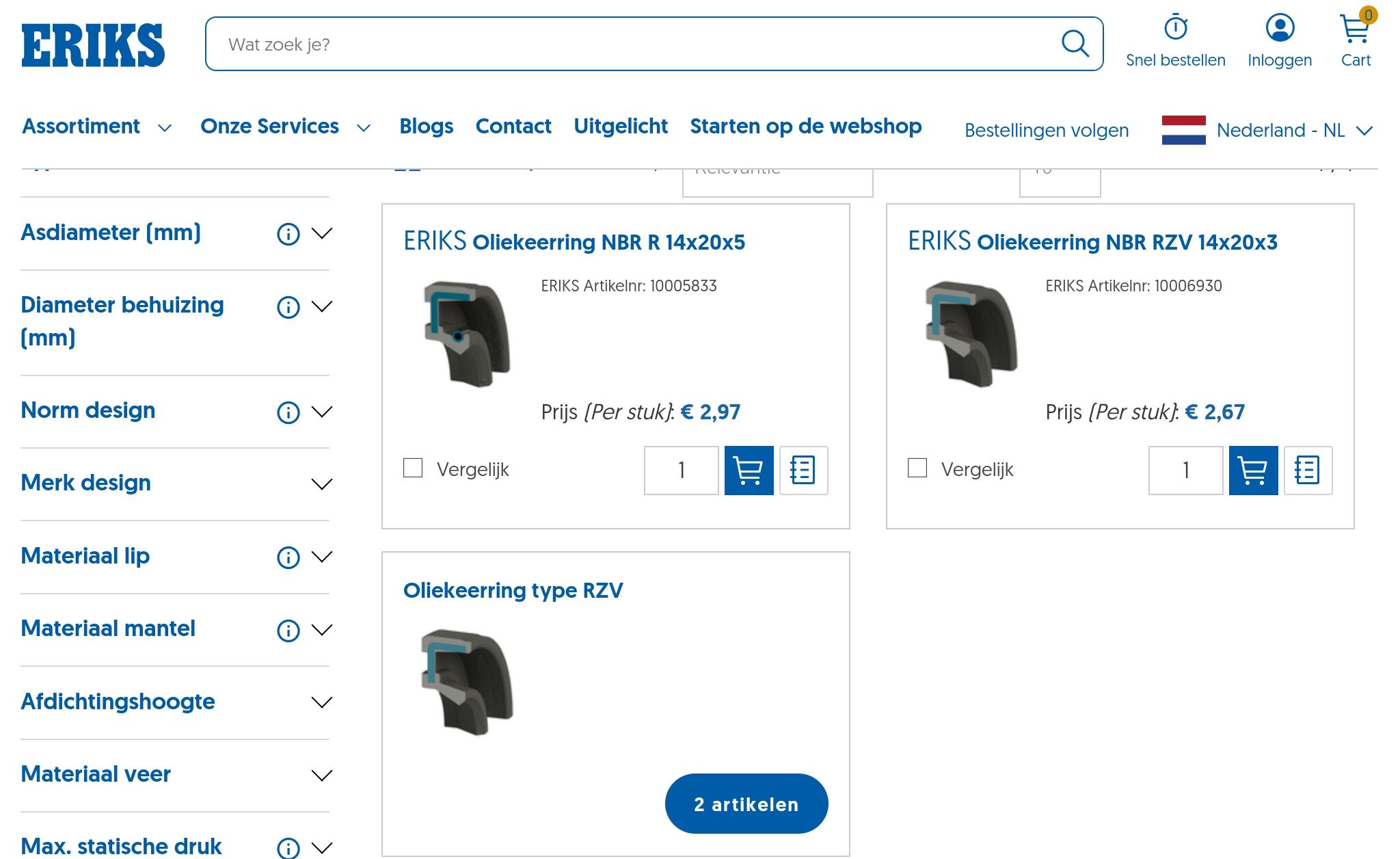
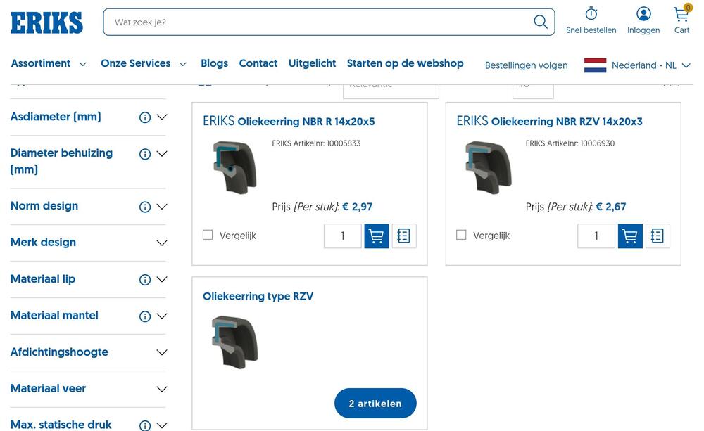
The striking rod oil seal is easy to find in the aftermarket suppliers. Don't use a hydraulic oil seal. They are a different design. The 5mm thick seal will also fit. It needs to have an ID 14mm and OD 20mm. (14/20 x 4.2mm or 5.0mm). Over here they cost a little less than €3.00. I mentioned the size in my list I made back in 2012. Make sure the rear bush is the Omega machine tool variant. It is not for our transmissions, but it is so close to the original that is is a suitable alternatieve. The SKU: 303066 (NIS-62) only fits the stubby FS5W71C transmissions for 4 cyl models. The transmissions with the long rear extension housing never had the option to replace this bush, not through Nissan anyway. I think the stubby transmission housing provided more stress to this bush and it was prone to wearing out. The NIS-62 is also much shorter and has less surface area.

-
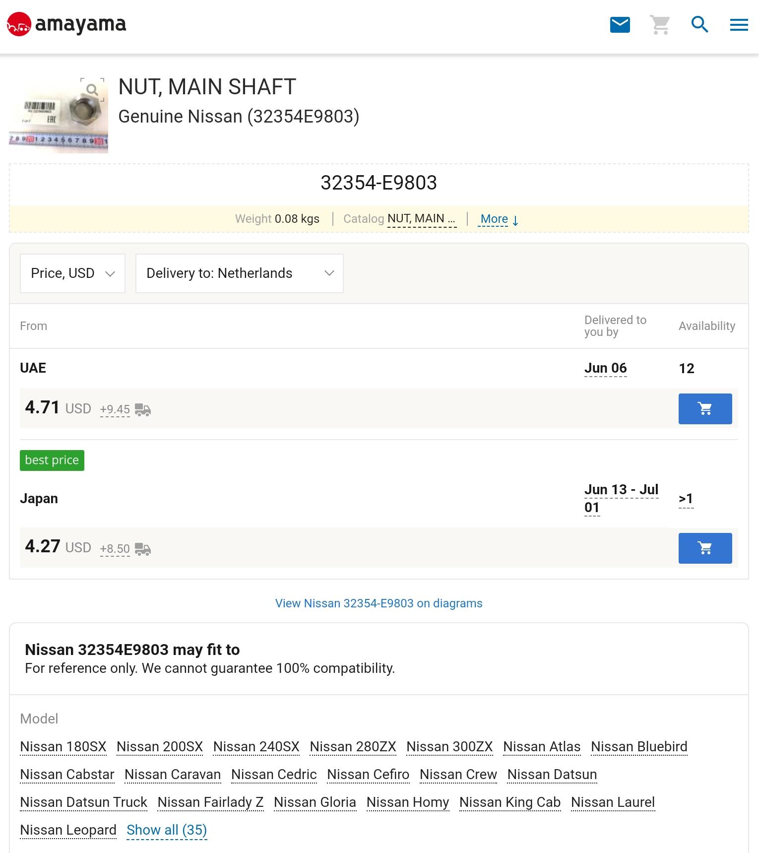
All part numbers 32354-A7400, 32354-E9800, 32354-E9802, 32354-E9804 are Right Hand Threads. Part number 32354-E9803 has a Left Hand Thread. The E9800 was used in the early 200SX 1979 - 1980. Right hand thread and replaced by the E9804.

-
All part numbers 32354-A7400, 32354-E9800, 32354-E9802, 32354-E9804 are Right Hand Threads. Part number 32354-E9803 has a Left Hand Thread. The E9800 was used in the early 200SX 1979 - 1980. Right hand thread and replaced by the E9804.
-
All part numbers 32354-A7400, 32354-E9800, 32354-E9802, 32354-E9804 are Right Hand Threads. Part number 32354-E9803 has a Left Hand Thread. The E9800 was used in the early 200SX 1979 - 1980. Right hand thread and replaced by the E9804.
-
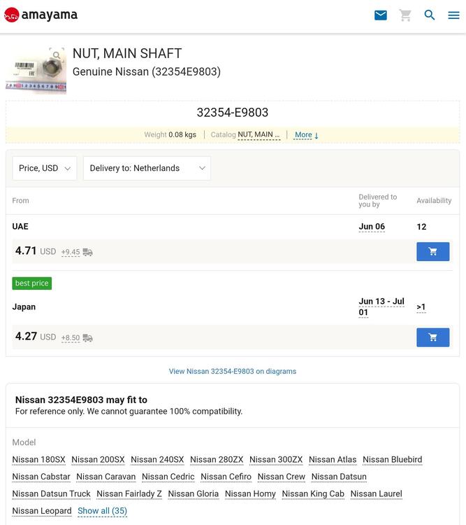
It's actually the right hand thread that is NLA. They changed when they started making the close ratio transmissions in the 280ZX. The LH Thead M27 x 1.0mm is used in a variety of models like the Urvan, Infiniti, 240ZX, 280ZX, 300ZX, 720 trucks etc. The RH Thread M27 x 1.0mm has been NLA for a very long time. Someone on this forum made some for other members a while back. You can re-use the original nut if you can open the indented section and remove it without to much trouble. When you rebuild and it lines up on the used section of the nut, you have a couple of options: 1. Machine 0,5mm of the nut face, then the nut will turn a furthe 180° or 2. Use 0,5mm shim. Any thickness will do as long as it is not 1, 2 or 3mm.
-
Btw: If the wire diameter, spring diameter and materials are the same, the spring with the less coils (green circle) will be a lot stronger, but will have less travel. Based on the law of Hooke. Hookes law: F = kx (F is force, k is spring constant and x is distance travelled.) Wire diameter: When the wire diameter increases, the spring constant also increases. A thicker wire ensures that the spring constant becomes stronger and is even more difficult to deflect. Spring diameter: An increase in the spring diameter will lead to a decrease in the spring constant. Number of turns in the spring: The higher the number of turns, the lower the spring constant. It would have been interesting to test the springs with a weight to determine the k factors.
-
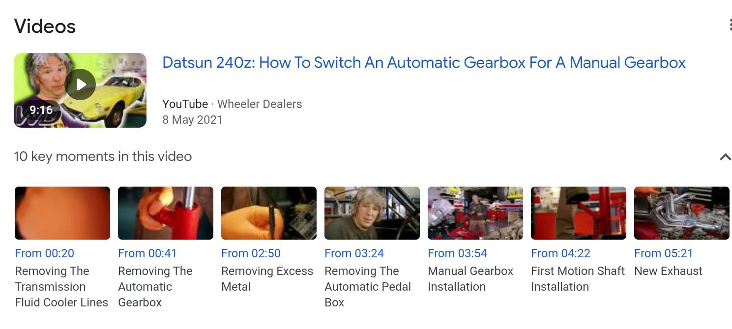
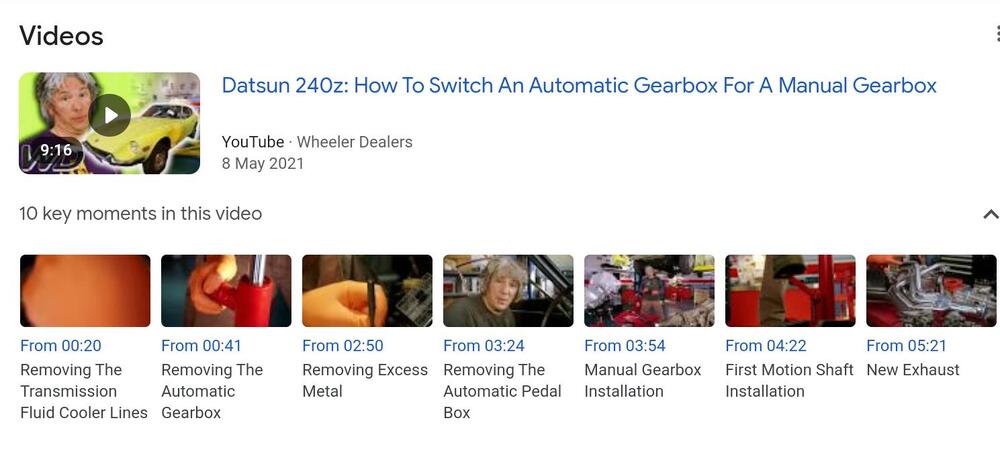
In Wheeler dealers they changed the auto to a 5 speed transmission in a 240Z. They show cutting out the floor piece and installing the shifter. Watching it might help?
-
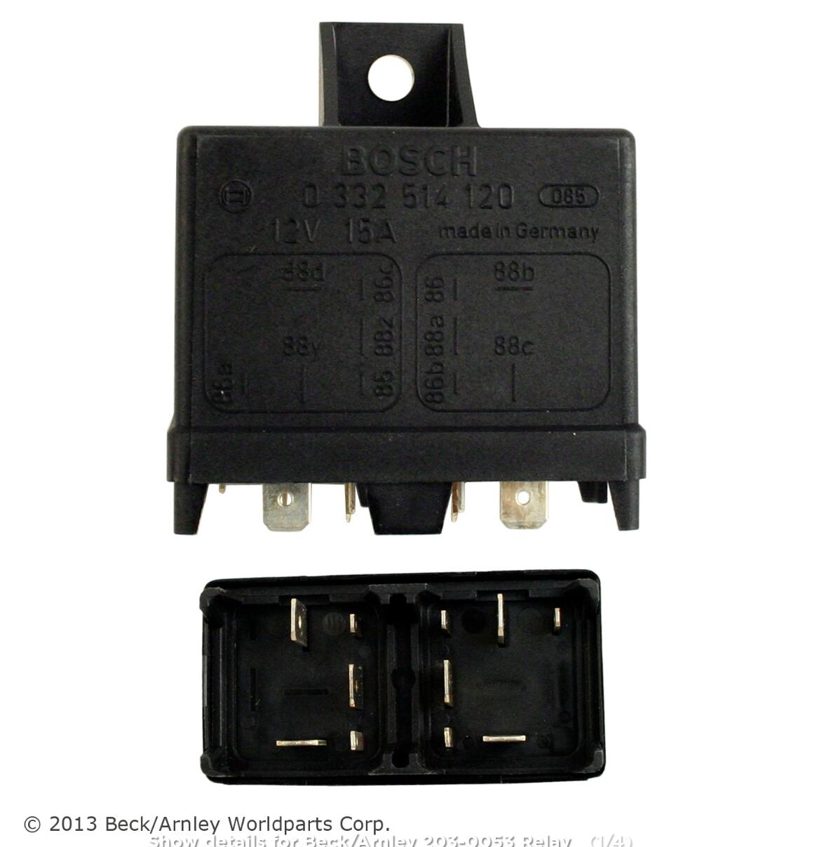
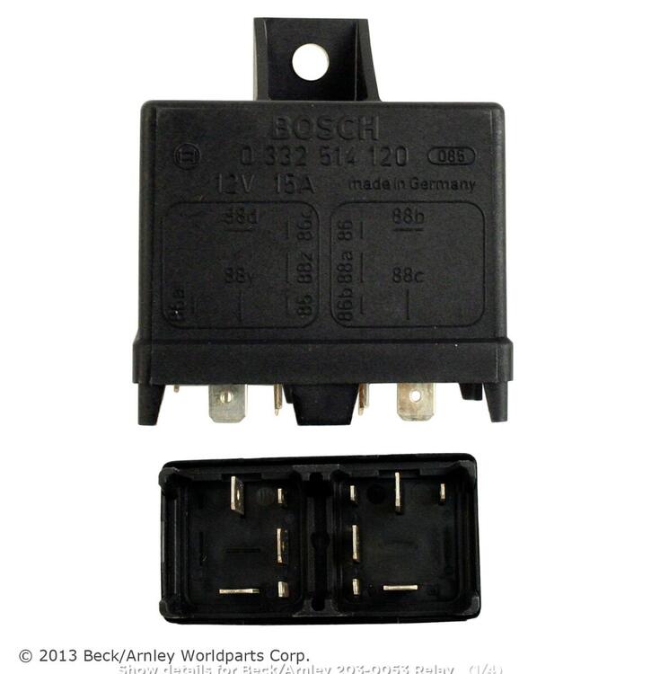
Congrats on the quick fix. You are lucky to have a Bosch 0 322 514 127 Fiat relay handy. These dual units are getting harder to find since Bosch stopped making them around 2020. Something I found years ago. If you are looking for a Bosch 0 322 514 120, try Beck Arnley 203-0053. It's a Bosch relay, but they just took it out of the Bosch box and put in a Beck Arnley box. It is also hard to find, but the more options increase your chances of finding one.
-
Mine will hold more than 1.5bar pressure for a least 2 weeks. It took me a while to get it that far, but replacing the check valve on the fuel pump was my eureka moment.
-
When you change multiple things and something goes wrong it will always be a challenge with fault finding. If this problem wasn't there when I started, I would be changing things back one at a time to try and locate the cause of the problem. The question is: Can you change back or are you past the point of return? You already swapped the TIU and tried other coils with no improvement so the problem doesn't seem to be related to those units. I'm interested in the Volvo IACV thingy. I probably should read through the other thread, but I'm feeling a little lazy so I'll just ask. How does the Volvo system know where the idle is? The timing light seems to indicate no issue with spark, but could it be interfering with the ECU and fuel management? I don't think your problem is fuel delivery. You can have a blockage in the injectors and that will cause fuel starvation. If it's a blockage in the fuel system, then it will be after the fuel guage.
-
It's hard to believe a 125amp fuse blows by swapping the reluctor wires, but there must be some relation if that is the only change you made before the fuse blow. I had similar problems with not revving past 2500rpm. Mine would rev cleanly to 2500rpm and then sputter around 2500rpm. It wasn't a hunt, more erratic running. I'm doing this from memory, since it is some years back. Like you noticed, I accidently swapped the green and red wires on the HEI terminals when I quickly fittrd it for testing. When I changed them back, the promlem was gone. FUEL: I don't think you have problems with fuel flow. If that was the case, you would loose fuel pressure. Pressure and fuel are very much related. You can have pressure with a restricted line, but when the injectors open for more fuel, the supply (flow) can't keep up and the pressure will drop. If your pressure is stable, then your fuel delivery is good. These old ECU's don't read fuel pressure. Bosch (and Hitachi) solved this by creating a constant pressure differential over the injector tip and using a Fuel Pressure Regulator with vacuum assist. Remember fuel pressure will follow the to vacuum in the manifold so I think it will vary a little with this problem. If you add a vacuum gauge next to the fuel gauge, they should work in unison. IGNITION: If you are using a 12volt coil then the ballast is not helping. It will reduce the voltage to the coil and cranking voltage is already reduce due to the high current draw from the starter. That was the whole reason for the lower voltage coils. During starting they would bypass the resistor and the coil would get battery voltage to help starting. Do you know the history of the Volvo coil? Could it be failing? Do you have another coil to test and see if that reacts differently? I'm still trying to get my head around your 125amp fuse blowing. It can't be going through the HEI. Nothing in the HEI can handle such high current draw. It must be a high labouring starter drawing so much current, but what could be creating such a resistance/load on the starter? Pre-ignition or timing firing way to early. You would think it would cause backfire. The motor is turning? I hope I'm helping and not adding to your problems. Chas
-
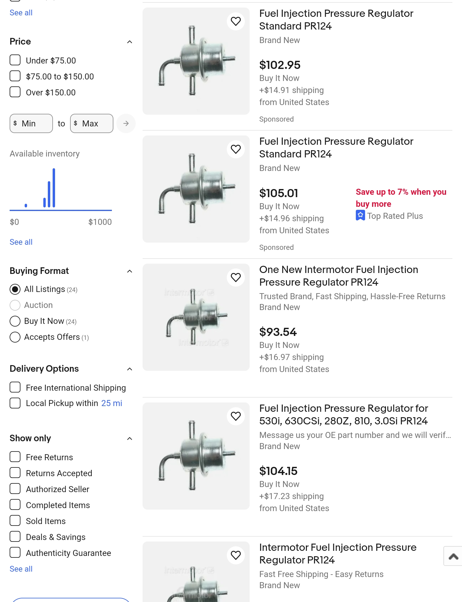
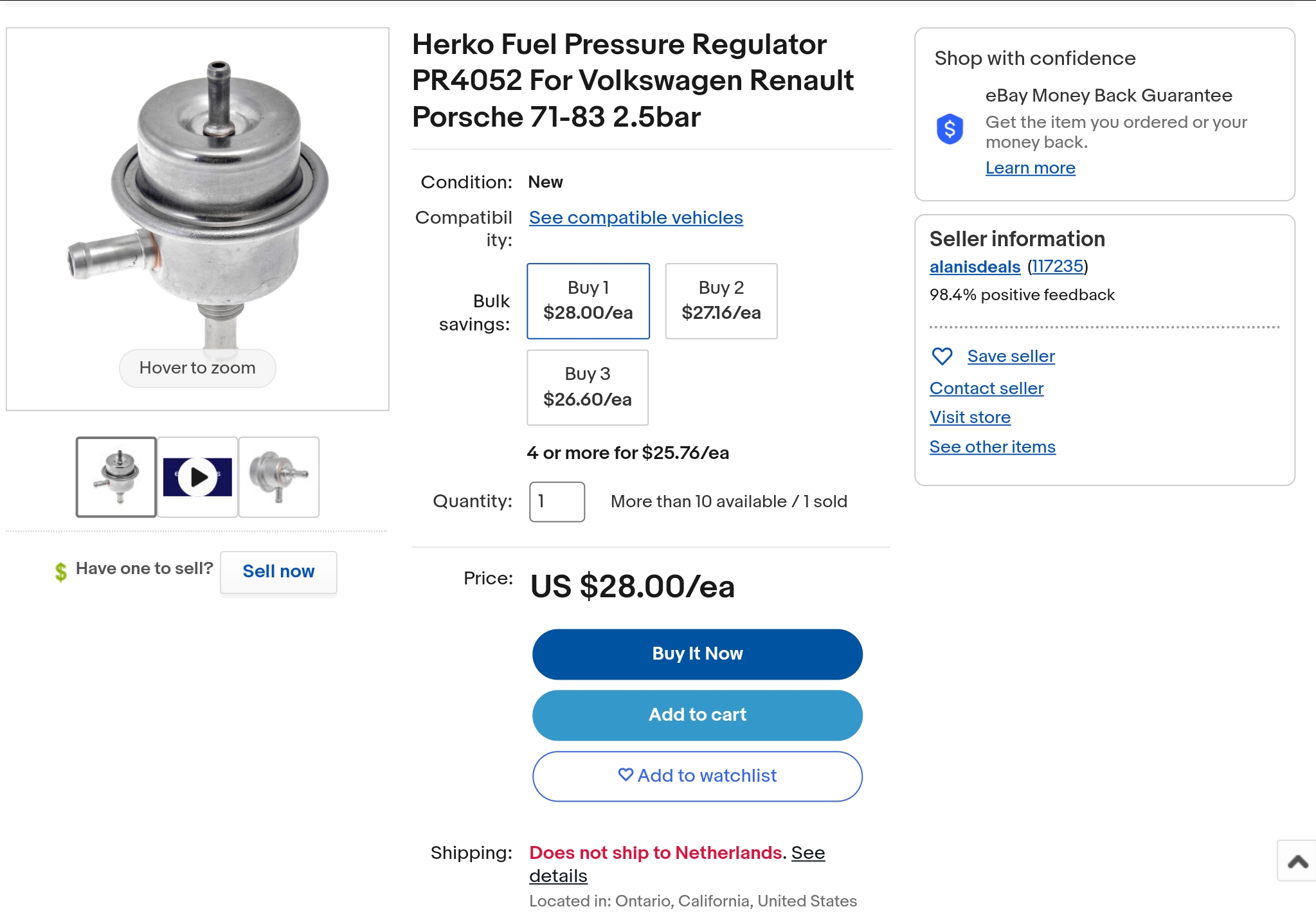
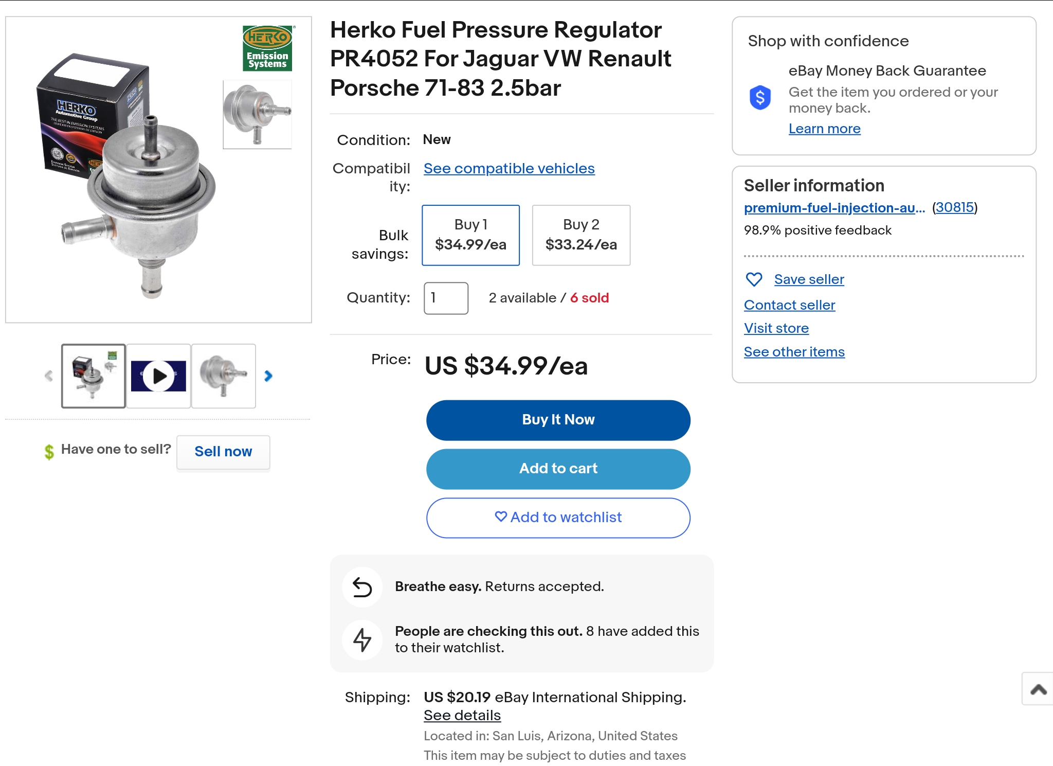
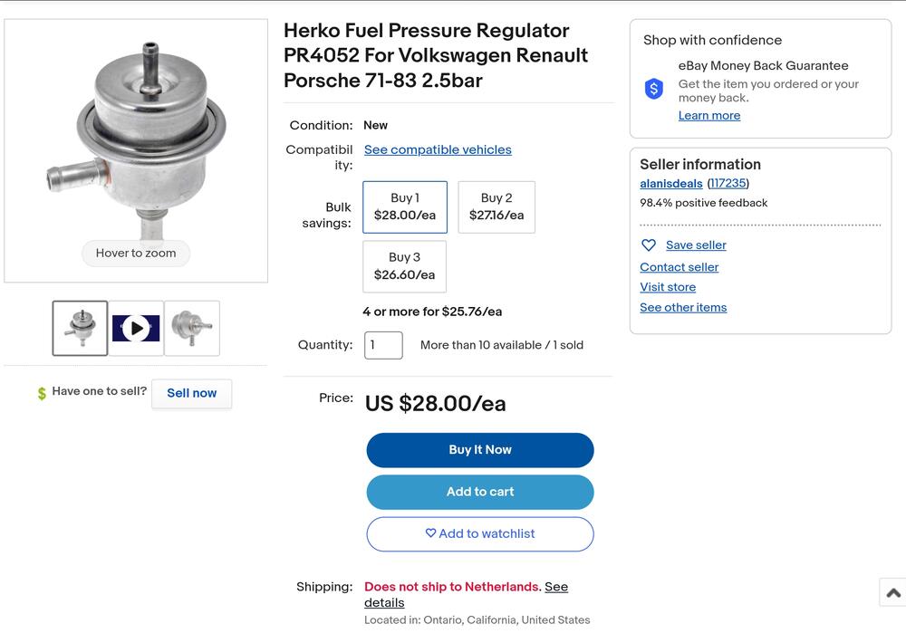
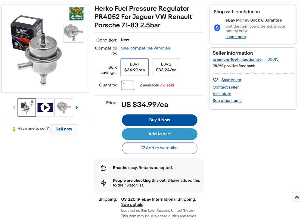
Shouldn't you be looking for thr PR4052? The PR124 is the aftermarket for the 280Z 74-77. Both are 2.5bar spec.

-
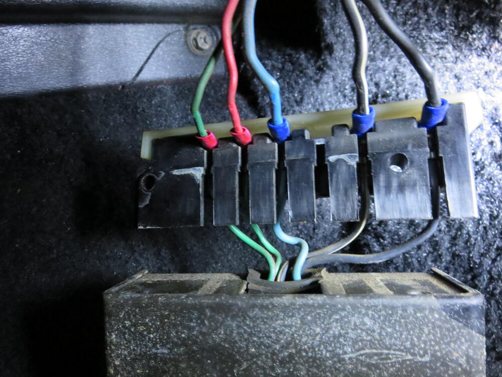
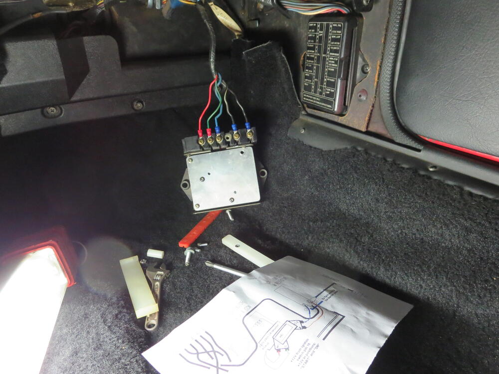
Hi Zed Head, The wires were switched accidently during testing. I'll take a new photo and update the Tech sheet. Funny thing, looking through my photos and I can't find that photo anywher. Must have deleted it. Here is where my dyslexie kick in and it all when south for a moment..... I did start on the correct side and after running the engine which would not rev over 2500rpm, I corrected it and back on track.


-
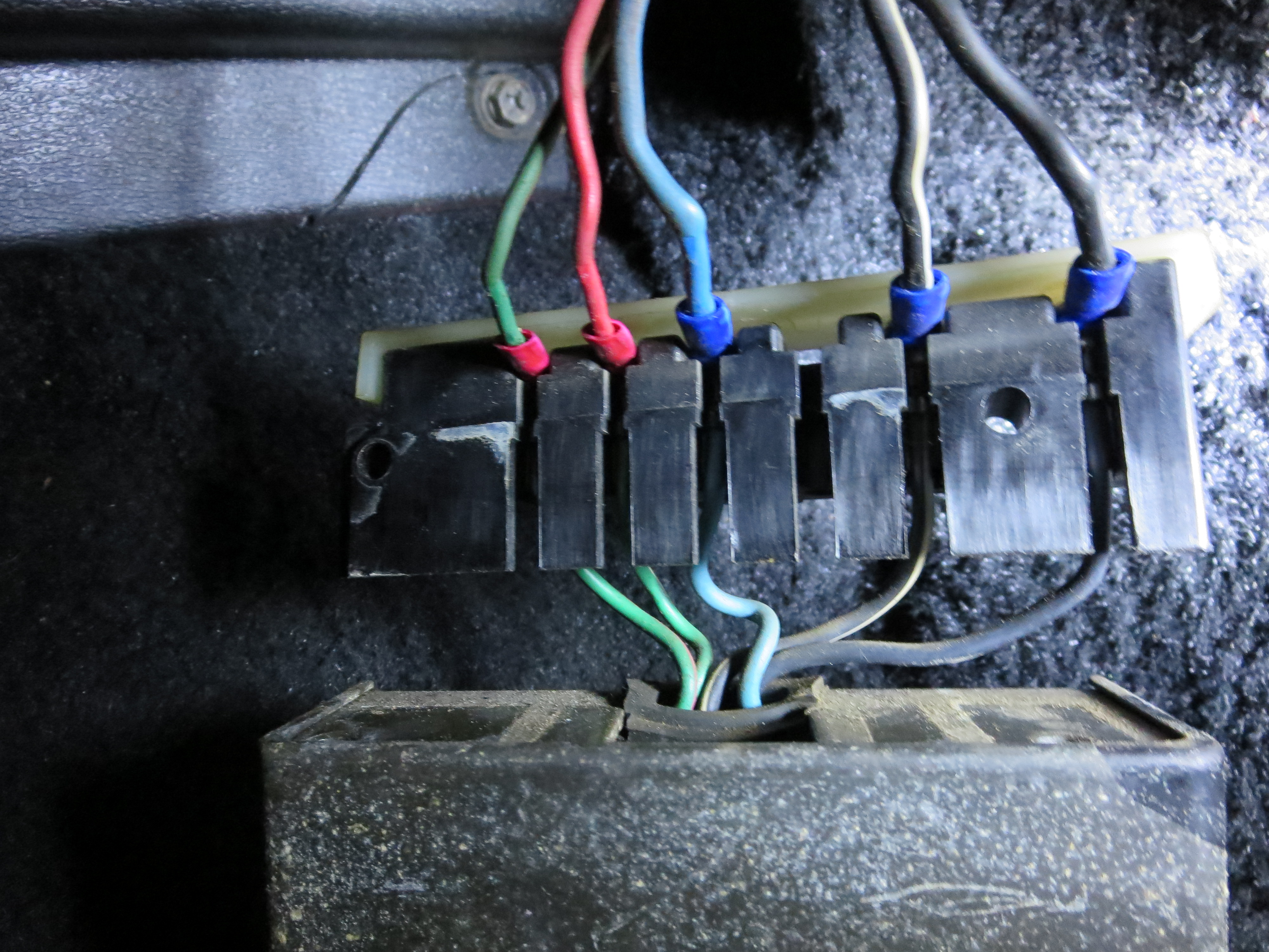
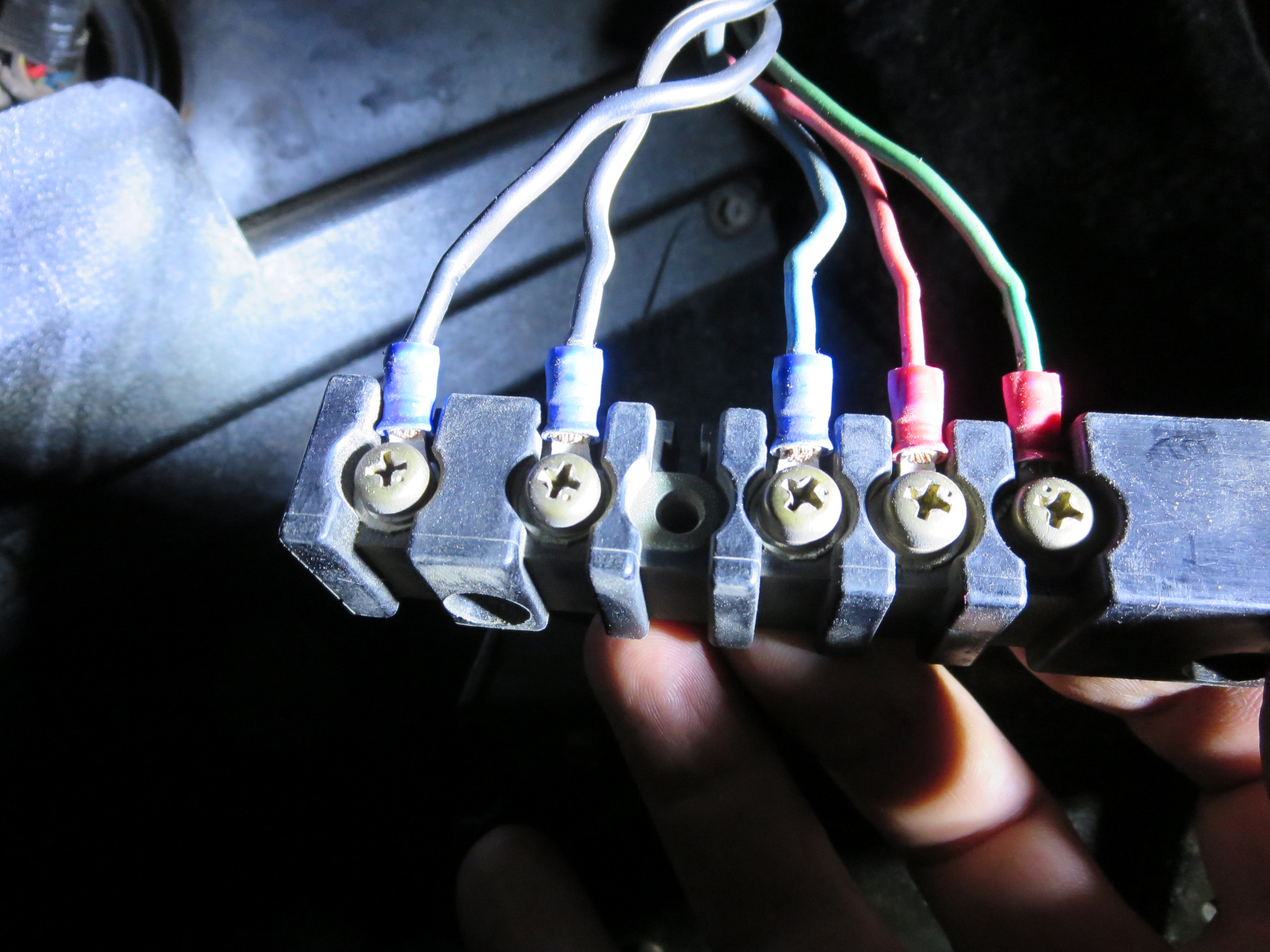
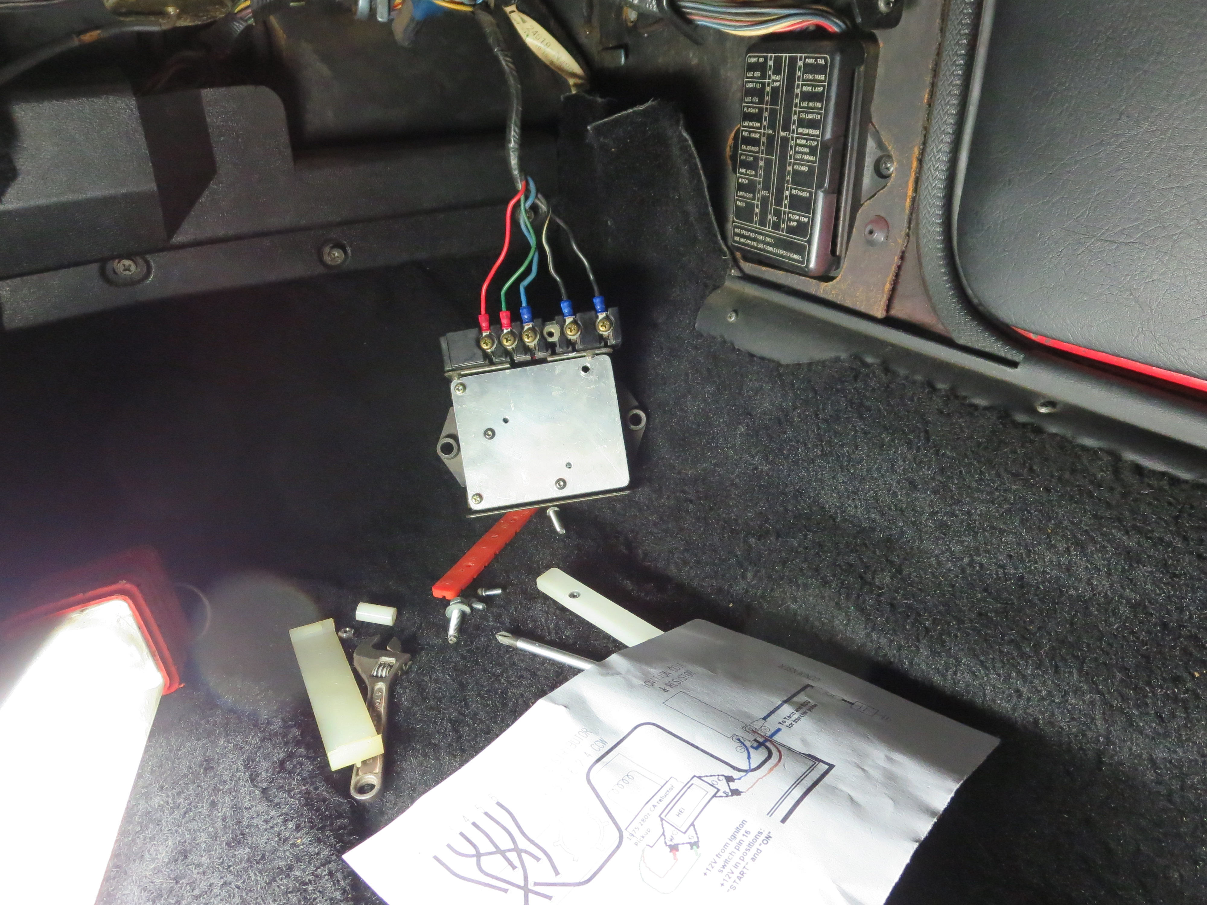
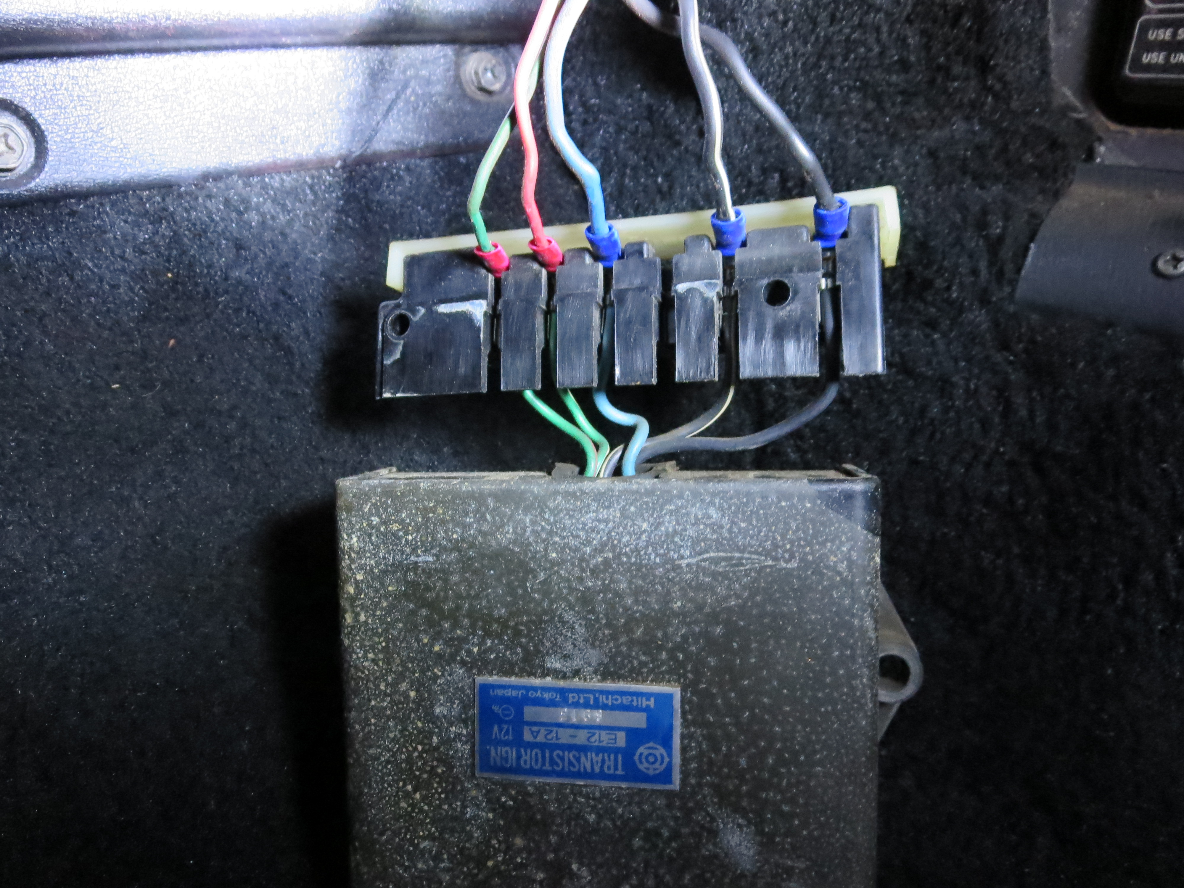
Hi, I accidently swithed the wires when I quickly connected the TIU for a photo. I noticed it a year or two later, but funny no one else has made a note of it until now. The wiring for the HEI is correct. Trust me, when I was first testing it would not rev over 2500rpm. That was because I connected the two red - green wires on the TIU backwards Working from left to right, looking at the TIU with the wires coming out from under the TIU. B - Black wire: HEI Ground. Very important. BW - Black/White wire: HEI B (battery) BW - Black/White wire: Not used. L - Blue wire: HEI C (Coil trigger "-") R - Red wire: HEI W (reluctor input) G - Green wire: HEI G (reluctor input) You can set up the HEI next to the coil if you want. Just disconnect all the wires from the TIU. You can then use the power to the coil to HEI B and the HEI C terminal can connect to the coil negative. The blue wire on the coil negative will still need to be connected for the tacho to function. Make sure you ground the HEI well. PS: Agree with you on the terminal layout in the electrical schema. I try to find a terminal that is not full. Say it has 7 wires in a 8 pin plug, then I can figure out which direction I need to look at it.