


Captain Obvious
Community Member
-
Joined
-
Last visited
Everything posted by Captain Obvious
-
Looks great. Doesn't have to take a lot of tension. Just has to keep the ends from flopping around out in the wind!
-
No biggie. The only reason I could tell it wasn't a ZX was because of the location of the BCDD.
-
So I (actually) read through the details of the thread this time and I think I have a better understanding of what's going on... The issue you are having is that the steering SHAFT that runs through the center of the steering column assembly does not seem to be grounded. The outer shell may be (or may not be), but that isn't good enough to get the horn the actuate. You actually need the rotating steering shaft in the center to be grounded. So, I agree though... I would expect the center shaft to get grounded through the roller bearings, but maybe not? Have you tried grounding the outer tube with a dedicated wire and seeing if that makes your horn work?
-
i like it!
-
If you've got play like that in the AFM, I'd just replace it with another one. Then after you've got it fixed, I'd autopsy the old one. Grind the stripped out screw heads flush and then pry that cover off. I would expect the sealant to put a fight though. I'd be interested in seeing the insides. It seems hard for me to believe that a bushing has worn out so much there is visible slop in the arm. Wonder what happened and why!
-
They were:
-
I have very little 240 experience, but I wouldn't expect the steering coupler to be the "planned" source to ground the steering column. I would expect the steering column to be grounded through the bolts that hold it to the firewall or the bolts that hold it up to the underside of the dash.
-
I'm not sure the Z had a temp controlled vacuum switch. I think the ZX did, but based on the pic above, this is not a ZX. And also on the Z, the ported vacuum signals for the distributor/carb can are a completely different source than the one that is used for the EGR system. Similar in concept, but completely different ports and actuation loads, etc. The "T" pictured above has nothing to do with the EGR system.
-
Correct, those two things you have circled should "T" together along with the carbon can.
-
Yeah. unfortunately that stud was molded into the rubber of the bumper end when it was molded at the factory. As Patcon suggested, about the only thing you could do now is grind it all out and glue something in as a replacement. And once you've gotten good at it by practicing on your bad one, I'd do your "good one" too, cause it looks like it's not long for this world either.
-
I'm lost... What's a "signal fuse"?
-
I think that "T" is supposed to go to the same place your distributor vacuum connects to. It's a ported source on either the front carb, or the EFI throttle body (depending the year) and "T" to the distributor advance and the carbon can.
-
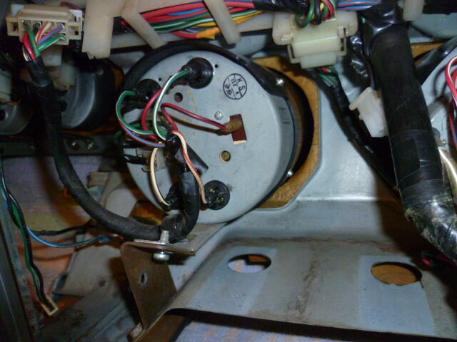
I found a pic of the back of the tach installed. It looks to me like they are grounding the turn signal indicators through the tach body and not through the harness? I don't have a tach here loose to verify, but it looks like that to me. That opens up the possibility for some other ideas. You can also see that they changed a bunch the wire colors on the little stub harness on the back of the tach. So you have to be careful about referencing wire colors since some of them changed at the tach connector:
-
So I got a chance to look at the wiring diagram, and here are my thoughts. First, the indicator lamps in the tach are simply in parallel with the corner lamps. The implication of that is... If all four corners blink with the turn signals, your non-functioning indicators in the tach have nothing to do with either of the flasher modules. It also has nothing to do with the hazard switch. Steve's thought about the ground for those two bulbs being broken is a good one, but I'm thinking if there was a problem with that ground, the tach wouldn't work either. Depends on where it's broken (if it's broken at all). So I have a C.O. question... What is the possibility you swapped the turn signal indicators with the tach illumination bulbs? Maybe you have the bulb sockets swapped? I remember you said that you don't care about the illumination circuit because you don't drive at night... I'm thinking maybe when you put a turn signal on, one of your illumination lamps is blinking and you just can't see it in a bright garage? Just tossing out theories. And for the hazard issue where only the left side blinks... I'm thinking that since all four corners work fine with the turn signals, then that problem must be inside the hazard switch. I took a refresher look and they do have separate circuits coming out of that switch for left and right sides. So it's completely conceivable that one dirty or deformed pair of contacts could knock out one side of the car's hazard lights.
-
Haha!!! I'm going to do my best to make that stick now. And good luck finding someone to let you borrow a mill. !! And glad to hear your pump seems to have survived the ordeal. I'm not surprised. It's not like you ran it for an hour with the milkshake in there. Just a couple seconds and you got it changed out now. I'm thinking it should be fine. Might want to change it again after a shorter than normal run interval just to be sure?
-
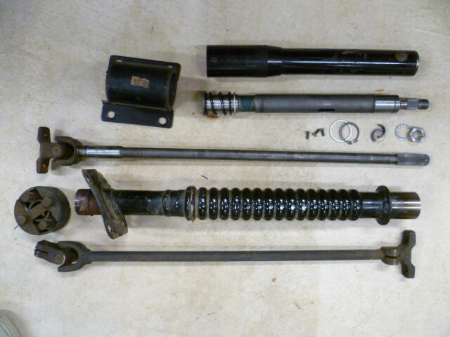
I don't think there's anything necessarily wrong with either of the insulators. The one on the right came from the rear of the car and the plastic spacer is stuck inside it. The one one the left came from the front and is empty inside because the pivot bearing stayed with the top of the strut. That's my take...
-
Haha!! Don't trust him not to drown it! I think he may have earned his verb... "Don't DaveWM your ______." (Insert noun)
-
Man Cliff, You are simply amazing with that. I was heavily involved in that discussion (that wasn't even that long ago), and I couldn't pull up the details. Thanks for having my back!
-
I've seen that brass orifice in years gone past, but it's been so long that I don't remember where Datsun originally put it. I suspect it was stuffed into the rubber tube that connected between the carbon canister and the return hard line up in the engine compartment. I looked a little through old pics and didn't find any. I've got vague recollection about talking about it here on the forum a long time ago. Maybe Cliff can Rain Man a link for us. And yeah, If you've removed the carbon canister completely, then in theory it really doesn't make any difference where you vent that line. Front of car, back of car... No environmental difference. Just make sure it's vented high enough so you don't ever dump liquid fuel out onto the ground.
-
Yeah... It's not supposed to do that. Guess you already knew that. So I looked at the FSM and the 74 does not have that two way check valve thing that the later years did, but there IS supposed to be an orifice restriction in the vent line between the rear of the car and the carbon can (FSM EF-33). If the line is plugged, I'd start there. It's probably green crusty brass at this point.
-
1. I shouldn't. There should be no way a bad tach should do anything at all to engine performance. Another reason that I question the coincidental nature of the events. Unless the insulation on one of the ignition wires has split under the dash and is shorting to ground or something, ignition should not be affected. But even that I don't think that should peg the tach at full scale. 2. Not really. You would have to unplug it from the harness running through the dash and pipe your own signals to it. 3. Bench testing would be a little complicated. Power and ground are easy... Generating the RPM signal for the other two wires could be a little trouble without some electronics equipment. I don't think you would be able to generate a signal fast enough just by hand. You could do it using your car with the tach sitting on the fender near the coil and some wires connecting to appropriate locations. Not the simplest thing.
-
Yup. I won't know for sure until I try it. I may have to make another adapter out of stouter stuff. We'll see.
-
Gotcha. So no... I don't have any theories at this time other than your tach has failed internally. However, the coincidental nature of that failure occurring at the exact same time you were messing around with other stuff in the dash makes me think it's something else. Maybe SteveJ has some additional theories?
-
Yeah? Ya think? So that evap-o-rust stuff is almost totally benign, so at least it's not like you did that with Ospho or something else more troublesome. Hopefully you can get your vacuum pump all cleaned out and no harm, no foul.
-
Wait... That's your A/C evacuation pump, isn't it?


