Captain Obvious
Community Member
-
Joined
-
Last visited
Everything posted by Captain Obvious
-
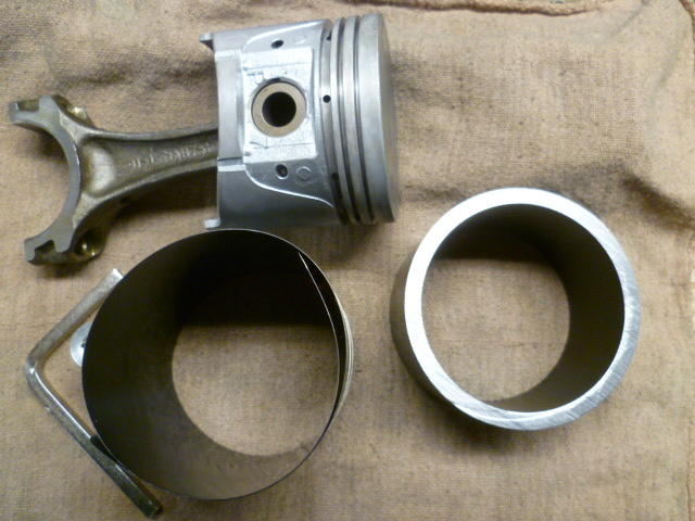
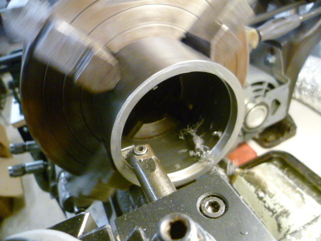
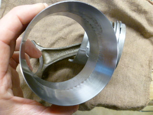
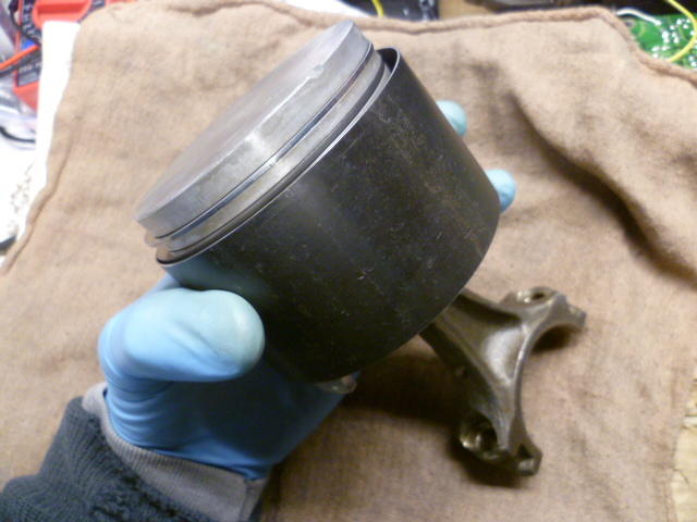
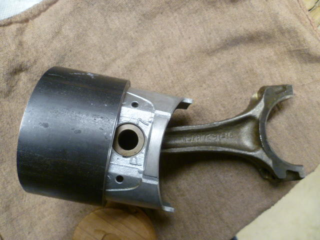
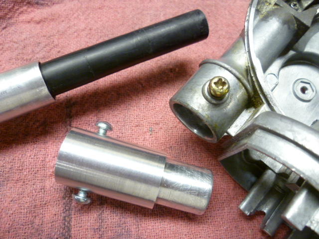
Yeah, I remember our discussions about that and I wanted to let you know where I am at this point... I only put one piston back in the block, and it was a PITA. Like you, I found the band style compressor to be very finicky. I'm assuming it gets better with experience, but it took me three tries to get the first piston back in without catching one of the oil rings on the block deck. Third time it snicked into position, but I'm just not happy with the compressor. I've actually got two of them and I'm not completely enamored with either of them. So I decided to try something different and made myself a tapered installation ring tool. Bought some steel tubing of appropriate size. Here's what I started with, Band tool on left, and thick wall tubing on the right: I chucked the tubing up in the lathe and bored it out to be a precision fit over the piston: And then I tapered one end with a gradual taper and polished everything up so the rings slide easy: The concept is you can slip a fully ringed piston into it and the rings will compress as you push the piston down the tapered section: And once the rings are all compressed, the theory is that I can just slip the pistons into the bores from here: And why does this pertain to ring gaps? Because since you're pushing straight down, the gap positions don't migrate. They stay where you put them. So I'm jumping the gun here a little since I haven't actually used it to put a piston into the block yet, but it worked great on the bench. What could possibly go wrong? go wrong? go wrong?
-
Well it wasn't a total loss, but it was one of those project steps which should have taken fifteen seconds turned into an hour of work. After the BFI removal, I cleaned everything up and made an "adapto-matic" extension to replace the original cut off portion and put the length back to where it should be. My aluminum adapter: Goop it up inside with silicone and put it back together: \ I actually made two adapters, but I don't remember exactly why. Either I needed to change diameters to use the mast from a different antenna, or it was simply "I cut it twice and it's still too short". Been too long to remember that detail, but in the end, the mast looked like this and it worked great: So like so many projects, it wasn't a total loss, but it took way longer than it should have because of unforeseen surprises.


-
Q - "How is the (defrost) indicator connected to the Timer?" A - It's not. Q - "Why does the Defog switch operate the heating elements, but not the indicator?" A - Probably because the defog indicator bulb is burned out. So how can those answers be correct despite all of your intensive research? It sounds to me like there are two faults... 1) Your defogger indicator bulb IS burned out, and 2) You have the indicator bulbs for the defogger indicator and fasten seat belts indicators swapped. Without being able to take any measurements from here, that's the simplest I got. Does your blue "FASTEN SEAT BELTS" warning lamp come on when you turn the ignition to "ON"?
-
I had one that was so corroded that I simply could not get the mast out of the lower housing. I finally resorted to the brute force and ignorance method. Now that I've done that once and know what I'm dealing with, I might be able to come up with something a little less destructive next time (if there ever is a next time). But since I had no idea what I was doing, I cut it off and mangled the shite out of it until it came out. :


-
Right. That's what I'm doing. The oil expander ring does not contact the cylinder walls at all, so there's no sealing implications there at all. I do suspect, however, that (because of friction) the bottom rings may not rotate at all, or if they do, I suspect they will all rotate together as a set. So my read is that it's important to get the two lowest ring gaps 180 out of phase, and the expander at 90 between those two. And I wouldn't be surprised if they always stayed that way.
-
Zed Head, I looked into the ring rotation a little, and you're right. Pretty much everyone says they rotate unless they're pinned in place. So knowing that, it seems to make the importance of the clocking of the ring gaps less important. One opinion I dug up said that it makes it easier to compress the rings evenly and install the pistons if the gaps are staggered. Another opinion was that it mattered in the initial start first few seconds of the initial start and then doesn't matter at all after that. In any event, I guess I'll keep doing what I'm doing, but won't get anal about nailing my 45 degrees exactly every time.
-
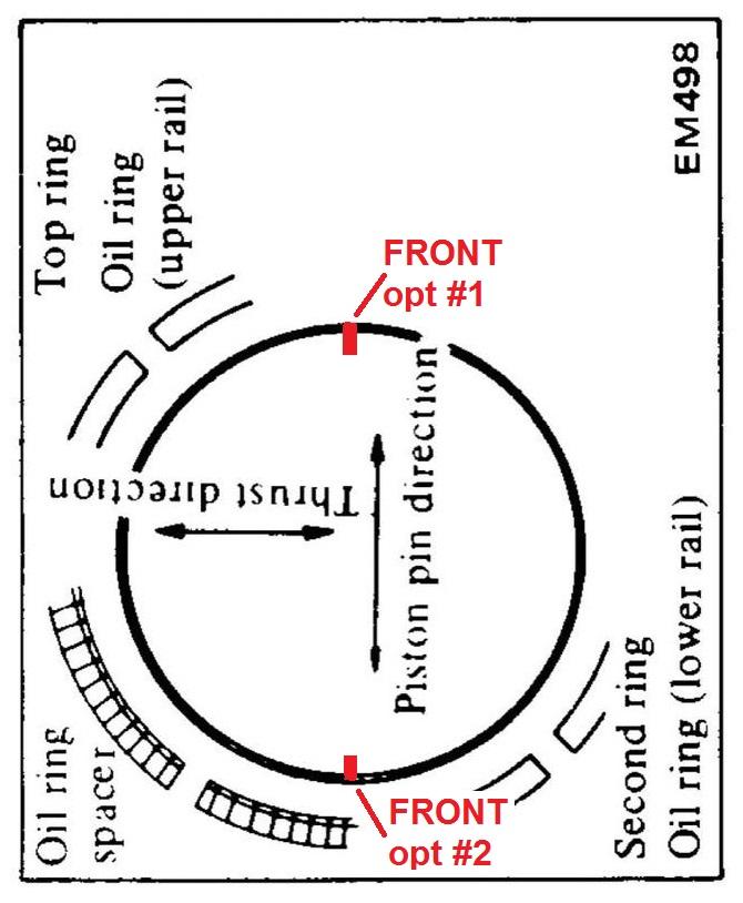
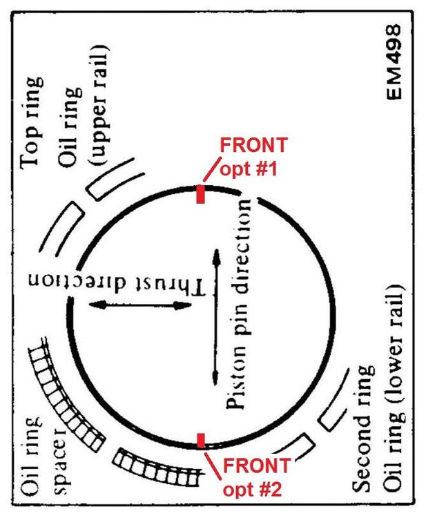
I find the pictures from all the FSM's a little confusion because they don't put the FRONT notch up top. All those FSM manual pics have the piston pin running side-to-side instead of top-to-bottom, and I just find it confusing because I want the notch at the top. To get the FRONT notch at the 12:00 position, you have to rotate that sketch. And also interesting to note that they do not specify "FRONT" at all. Just the piston pin direction. Seems it really doesn't matter which is FRONT. You could rotate that sketch either direction and it would still be right. I rotated it and put on the two possible FRONT notch locations: Either of those FRONT locations would follow the "rules". The FSM shows the pressure rings all at 4:30 and 10:30, but I don't see any reason why 1:30 or 7:30 would be any different.
-
My understanding is that the starting offset was to maximize the length of the path between compression and non-compression. The longer the labyrinth, the less leakage. And staggering the gaps +180, -180, +180, -180 is the best you can do. And while some things are designed to "walk", I don't think the rings are one of them. I believe the gaps are intended to stay where you put them. But all of this is why I'm hoping some of the engine builder experts will chime in. I have all my rings on pistons but haven't put the pistons back in the block yet. I still have time to completely change all my gap locations if someone throws their body in front of what I'm planning.
-
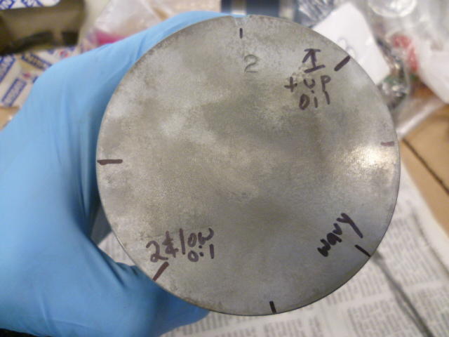
Good timing. I'm messing with the same thing right now. I didn't find "clear cut positions" anywhere either, but I believe the overarching gap position rules go like this: 1) All the gaps should be at a 45 degree angle away from the piston pin center 2) The 4th (bottom) ring and second ring gaps should both be in the same as position 3) The 3rd ring and top ring gaps should be 180 degrees away from bottom and 2nd 4) oil wavy ring gap (expander) should be 90 degrees from all the other rings Some additional rules, not specifically related to gaps, but since we're talking about rings, it's probably appropriate to mention them here: 5) Put the wavy expander in first and make sure the split portion is titts down, like an "M". 6) The thin 3rd and 4th rings do not have a top/bottom. Doesn't matter. 7) 2nd and top rings DO have a top and bottom and make sure you have identified that and get them on correctly. So, interpreting those rules... Put the waver scraper ring on first. Pick a position for the gap. The rule is "45 degrees from piston pin", so you have four choices - 1:30, 4:30, 7:30, or 10:30. And then once you have picked a position for the expander, the rest of the positions should fall into place. An example: Put your wavy expander at 4:30. This mean that all your other gaps must be at 1:30 and 7:30. Fourth and second being the same at either 1:30 or 7:30, but third and first must be opposite. I looked closely at my block and tried to figure out where the rings originally were from the factory and then when I put the new rings in, I tried to put them somewhere ELSE this time. Figuring I would "even things out". Not sure it makes much difference, but that's my plan. Before I put the rings on, I marked the piston tops with sharpie to make it easier for my little brain to keep things straight while moving the gaps around. I'll clean the sharpie off after the pistons are installed. Looks like this: However, all that said, please note that I'm no expert in such matters and give a little time for other people to throw their bodies in front of advice before you put all your pistons in. I'd like to give other people some time to tell me just how wrong I am before you go and repeat mistakes that I've made.
-
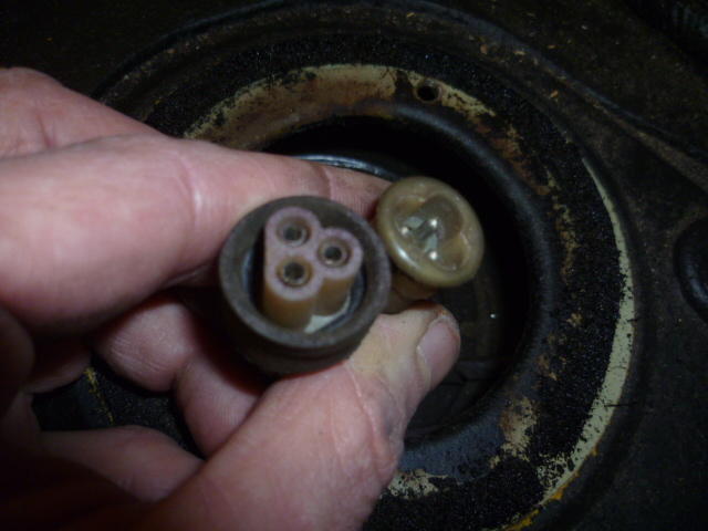
Yeah, that one was a real bonus! I was cleaning that connector with the 100% expectation that it wouldn't have any effect, but (roll eyes) I had to perform due diligence and clean it before I moved on to more difficult solutions. It was just the right thing to do. Bonus!!! Sometimes you win one! I guess I'll keep that new sender lock ring and sealing O-ring in a box on the shelf! Haha!! And buy a lottery ticket?
-
Exactly. That's what it sounded like to me, but I'm having a hard time believing that he got two senders with the same blob in the same location.
-
No, I think if it were resistance in the wires (and connectors), it would do what you said... Inaccurate through the whole range. SOUNDS like the sender unit has a dead spot below 1/3 tank, but I'm having trouble explaining the exact same behavior with two different senders. I'm also having trouble explaining how bending the arm could fix this. (But full disclosure, I've never messed with the sender units.)
-
-
-
Chase, So your gas gauge works fine for all situations except when the tank is about 1/3 full? If that's the case, then I'm having a hard time coming up with any answer other than a problem with the sender unit. I know you replaced that and it didn't fix the problem though, right? Does the new replacement act just like the old original sender unit?
-
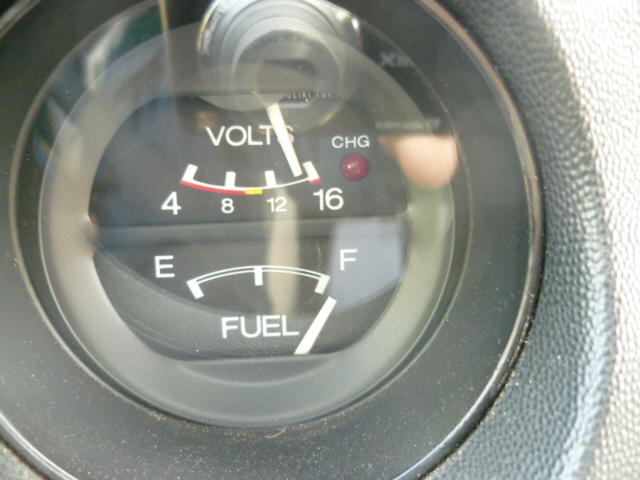
I filled up my gas tank yesterday for the first time since cleaning the connector pair at the sender unit, and guess what!!!!?? My gas gauge now reads significantly higher than it used to before cleaning that connector. Here's a full tank now. It used to read at about 7/8 full (even when full), but now it looks a whole lot better: So for me, cleaning this connector made a big improvement: I may still pull the sender unit out of the tank for inspection, but the priority just dropped down on the list a bunch!
-
-
So that looks OK to me (now that I can see it). I put in a section for "Mid-year changes" in the 260 folder just to see how that would look. I guess the first major question to debate is... Would it be better sorted by item specific changes (like seat rails), or as a design timeline (most likely by year)?
-
I can't really tell what the wiki style would look like without an example, so I put in a couple years just as a test. I don't know if anyone else can see that categories I put in. Says it needs to be approved by a moderator.
-
Man that looks fantastic. I sure wish I had something like that in my car. I don't drive it in the middle of winter (when there's salt on the roads), but there's still a significant portion of time before and after that when I would really enjoy seat heaters. I either need warm air blowing out of the dash vents, or I need to stick one hand at a time under a leg to warm them up. As of right now, I still haven't figured out an easy way to get hot air out the dash vents, and sticking fingers under a leg against cold vinyl just doesn't do it for me.
-
I think the idea is great, but the implementation is clearly up for debate. How about a simple description of "differences from the previous year" and then if there are questions or requests for pics about something specific, they can be added. Just to illustrate things, I tried to pick something that everyone knows about from each year: 72 240: Changed from the four screw round top carbs to the three screw and routed water into the carbs to heat the nozzles 73 240: First year for the flat-top carbs 74 260: Changed the seat rails to a new design First year for shock absorber mounted bumpers 75 280: This is the first year for the fuel injection 76 280: Increased the number of parking brake ratchet teeth Added weather strip rubber along tops of doors 77 280: Changed the seat rails to a new design New sheet metal stampings pretty much everywhere 78 280: Redesigned ignition module which allowed removal of the ballast resistor I'm thinking just keep filling in differences as stuff comes up?
-
My pleasure. Glad to help. And a hug would be nice too. I'm a lumberjack and I'm OK. So I was a little pressed for time earlier when I posted that diagram and didn't have time to talk about the use of flashing the high beams here in the US. First of all, if we here were to flash the high beams, we would just pull back on the HI/LO stalk twice in rapid succession. More modern cars have a "make-before-break" type of switch now, but back when the Z's were new, you just pulled the stalk twice. And even before that type of control, the homegrown stuff here often used a foot switch operated by your left foot. You would stomp the switch twice quickly. As for the meanings... Just like where you are, there are several different meanings to the flash. I don't know if there are regional differences in the USA, but where I come from: Quick flash at an oncoming driver can mean "I just passed by something that you might like to know about and you should pay attention." Things like debris on the road, animals along the side of the road, police ahead. That sort of thing. A quick flash at an oncoming driver may also be "You have your high beams on and it bothers me. Please put your low beams on." That may be quickly followed by a longer flash if the desired response is not achieved. A quick flash at an intersection means "You go ahead. I'll wait." A flash from behind usually means "Move over, you're driving too slow." The length of the flash is usually commensurate to how frustrated the guy in the rear is. A quick flash on a multi-lane highway after you have been passed by a faster vehicle means "You are safely beyond me and can tuck back into my lane if you wish." Most often used by trucks, but sometimes I'll give trucks that sign even if I'm driving in a car.
-
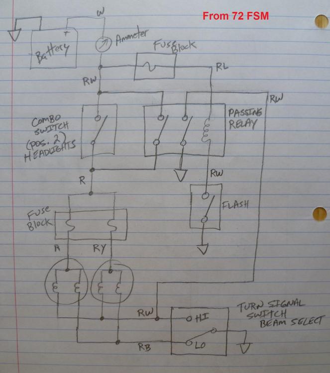
Here's what the 72 system (with the FLASH feature) looks like. Other than the addition of the FLASH / PASS button and the passing relay, it's pretty much the same thing they used in my 77. Point being.... I'm assuming that all the years in between are also the same, including yours. You can see that the pair of headlight fuses are not hot at all times, but are only hot when the headlights are turned on. You can also see that the headlight system has no interaction with the ignition switch at all, so the headlights can be turned on regardless of the key position. Same thing goes for the FLASH system. Also interesting to note that when you push the FLASH button, it will turn on the high beam filaments. Full stop. Doesn't matter if the headlight switch is on or not. Doesn't matter if the lights are already on in LO beam. Even if the low beams are already on, it will power both filaments at the same time while the FLASH button is being pressed. Hand drawn in all it's glory: Hope that helps!
-
The US cars don't have the flash button, so I'm operating without a net, but your diagram does not look right to me. In the US, the headlight fuses are not hot at all times as you have shown. The OFF-ON switch is between the battery and the fuse box. The fuses are only hot when the headlights are turned on. In addition to that, with what you have drawn, the ONLY way to get the high beams to light up is to push the flash button. I think there's stuff wrong... The newest thing I have here is the 72 manual still shows the FLASH relay, and the basic system is pretty much the same as the US with the exception that the flash relay is wired in parallel with the rest of the system and will turn on the high beams even when the headlights are not on. Would it help if I were to sketch up the 72 system?
-
Yeah, your fuel gauge looks like it reacts the same as mine. Always too low. I haven't done anything else with mine (since I cleaned up the connector right at the sender unit), but I fully expect my issue is inside the tank. Murphy's law pretty much demands it. That Z hasn't come back around on my work sheet yet. I've got all sort of other car work to catch up on. Today I changed the plugs on a V6 Kluger. Including the three invisible ones in the back... That's no fun. As for the bike "teaching moment"... Very nice! Thankfully, tis but a scratch!