Leaderboard
-
.JPG.cfcada9cf1c1b502df3f5f2f2ca3ff36.JPG)
SteveJ
Free Member6Points9,646Posts -
.jpg.697cae2dec04e3d7f78231df77a31622.jpg)
Ownallday
Free Member6Points198Posts -
Jeff G 78
Free Member2Points3,007Posts -
jfa.series1
 Subscriber
 2Points2,733Posts


Popular Content
Showing content with the highest reputation on 11/14/2023 in Posts
-
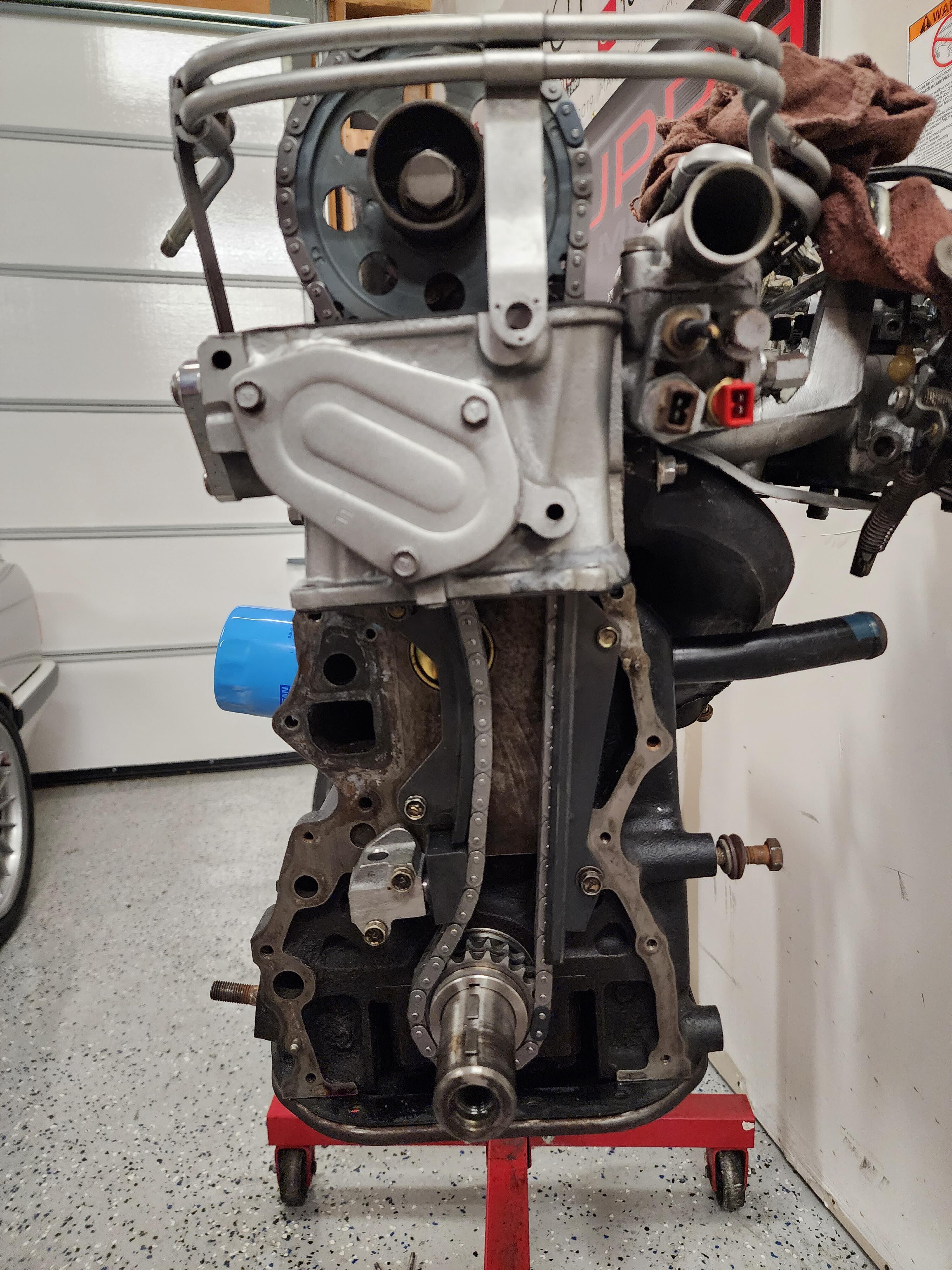
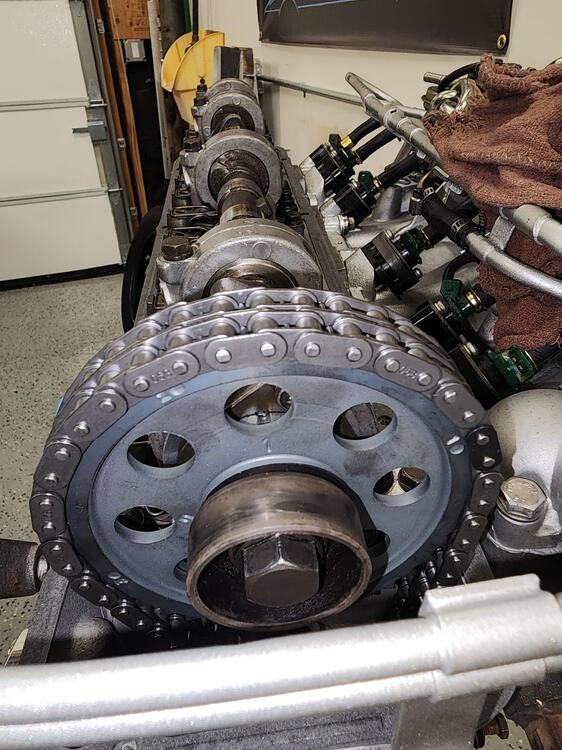
Thanks everyone for your feedback and knowledge. Was able to replace the timing chain and tensioner earlier today in about an hour. Happy to report the issue has been resolved and the tensioner is no longer crazy extended, safe to say the chain was just extremely stretched. Hopefully this week the car will be running again with a fresh new engine rebuild.
 3 points
 -
2 pointsIt's a breadboard, but you were close. The technical terms in America for that kind of relay are form C contacts and SPDT (single pole, double throw). The Bosch terminal numbers for a relay like that are 30, 87 (normally open), and 87a (normally closed).2 points
-
2 pointsWell, for whatever reason, my response from this weekend didn't post, but thanks to the software at this site, it wasn't gone forever. Let's look at the circuit for the fan. This is for the 240Z, so it doesn't show the ignition relay, but this is close enough for testing purposes. Also, this assumes you don't have factory AC in your car. The easy way to tell is that the factory AC cars had a 4 speed switch. (You have factory AC per another thread.) So, there is a 2 pin connector on the fan motor. Unplug it. With the key in ACC or ON, you should see voltage to ground at the red wire on that connector. Test for that and report your results. If you do see voltage to ground, you can turn the key to OFF. Now we will focus on the black wire on the connector. Put the fan switch on high. Measure resistance to ground on the black wire and record your results. Put the switch on medium. Measure resistance to ground on the black wire and record your results. Put the switch on low. Measure resistance to ground on the black wire and record your results. (Are you noticing the pattern, yet?) Report your results so we can see what to diagnose next.2 points
-
2 pointsThere are two wires coming from the motor that are connected to the harness going to the switch. Disconnect the harness wires from the motor wires. Ground one of the motor wires and apply a 12V power source to the other wire. Listen for the blower motor to respond. If it works then your problem is elsewhere.2 points
-
That looks about as similar to what I have now. That brings a lot of extra relief to me haha. Thanks for sharing. Will share pictures tomorrow of my results.2 points
-
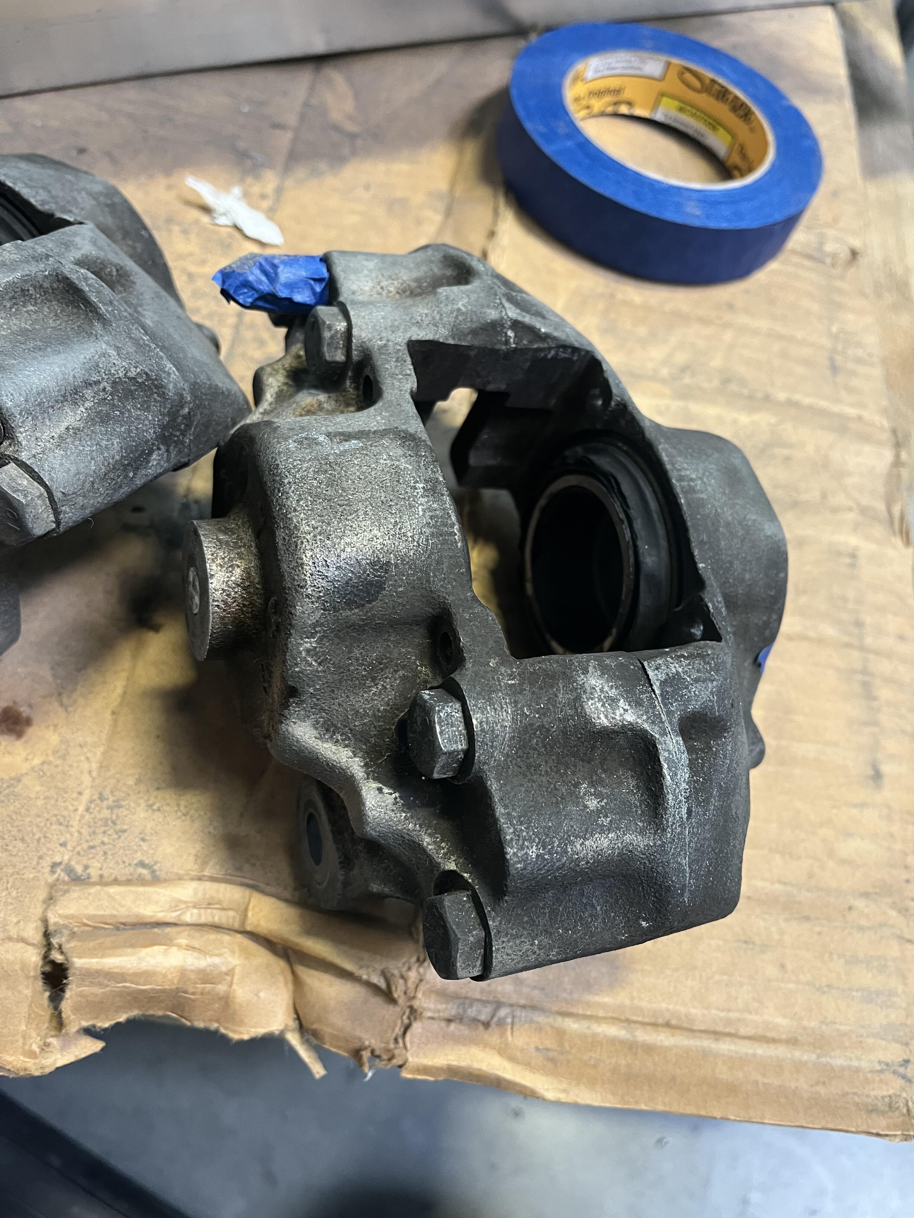
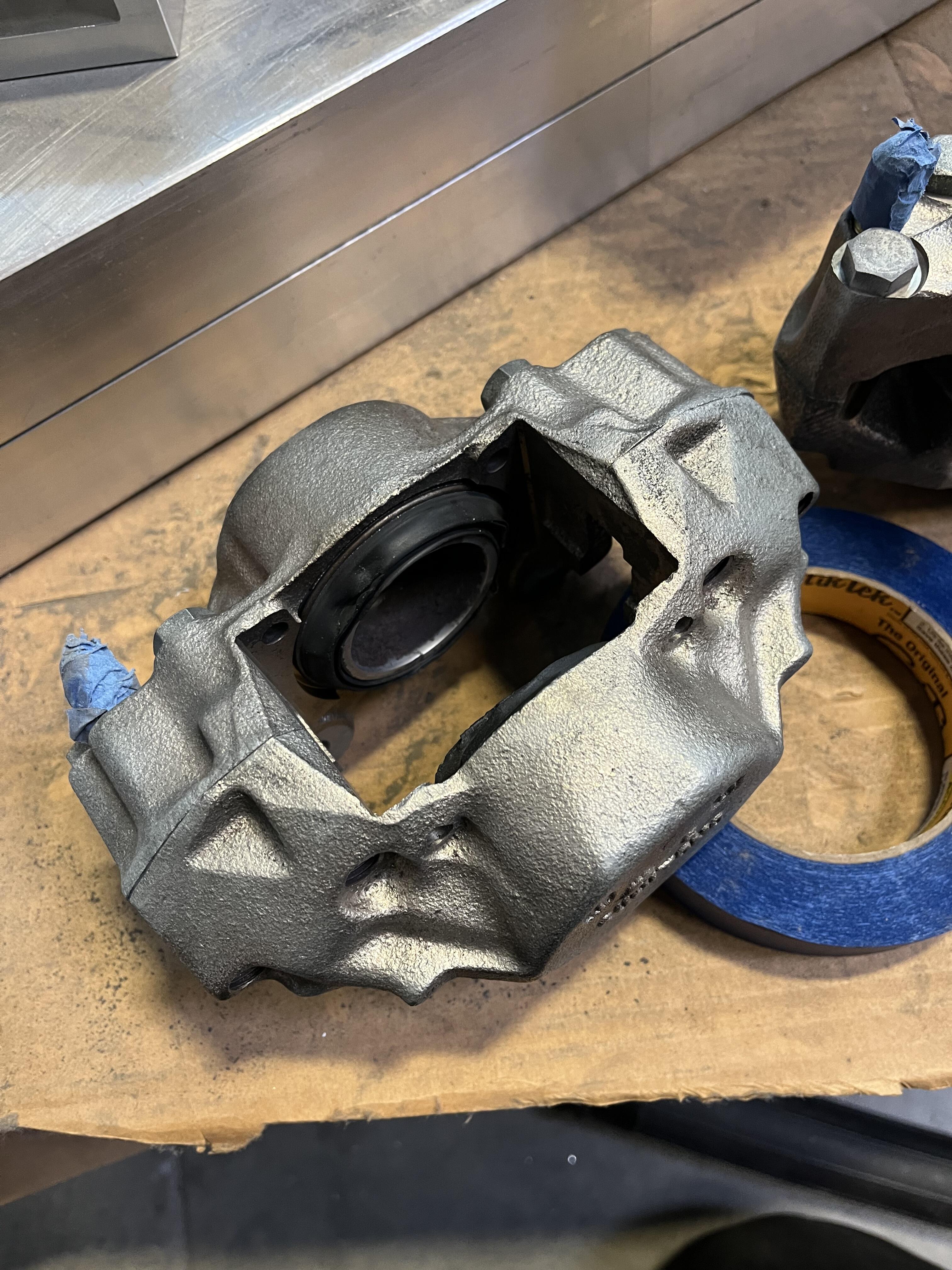
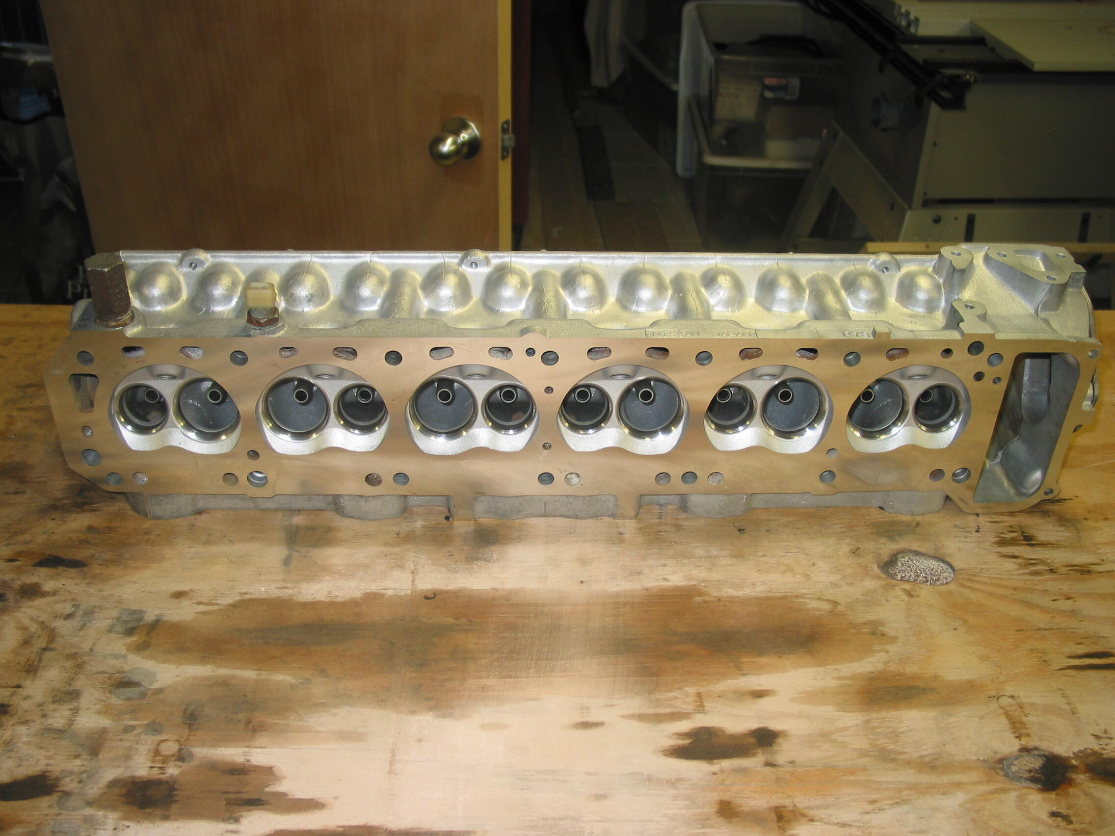
2 pointsWell I blasted them and they look pretty good raw so I think I'll leave them like this. I'm attaching some before/after pics. Thanks for the quick replies everyone! I left piston/seals in place so I didn't have to mask the bores. I'll replace all that stuff tonight when I rebuild.

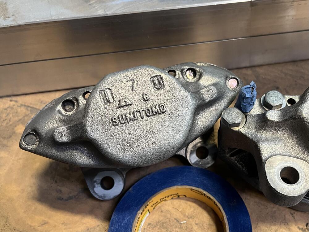
 2 points
 -
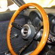
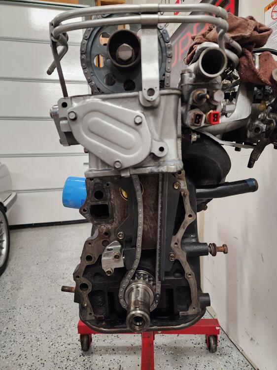
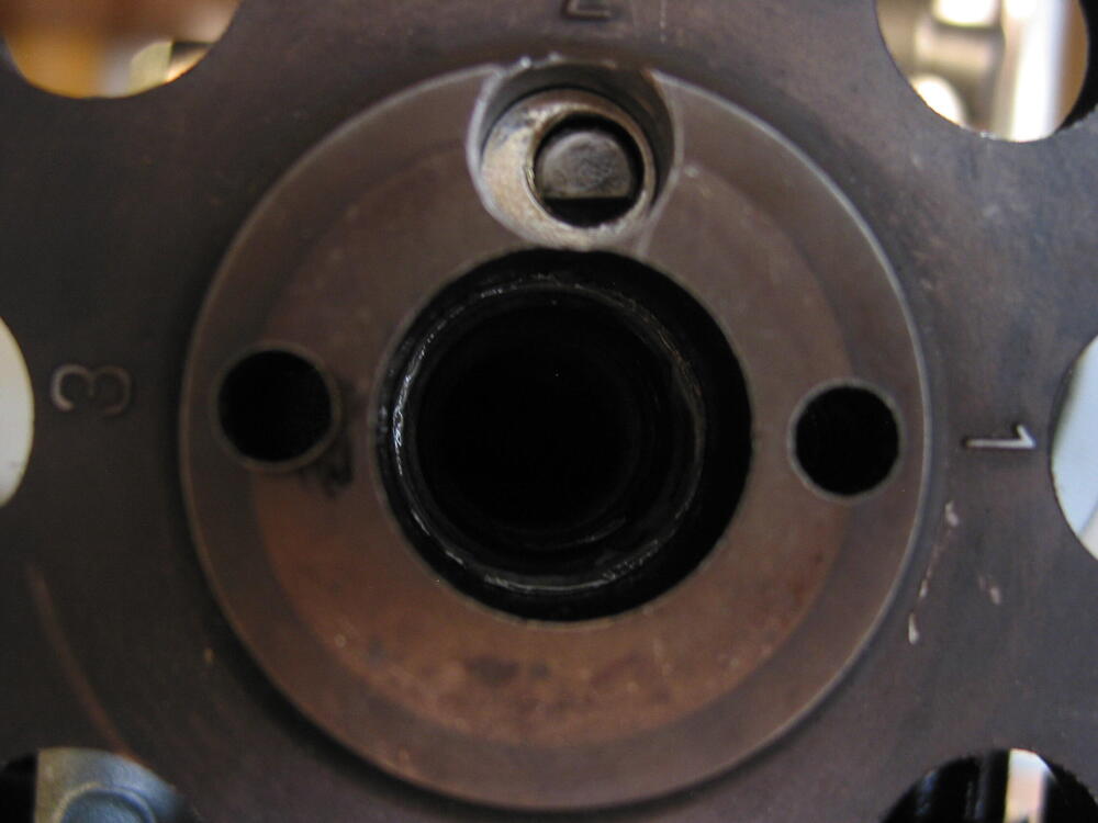
Hi folks: It's been a minute since I was on here last, but after much dithering the boys and I *finally* got our rebuilt harmonic balancer installed on our '74 260Z. My question is... How do you know it's seated where it needs to be on the crankshaft? It *looks* about right but is there a surefire way to know? Our latest video: Thanks in advance, MC1 point
-
1 pointI have these in mine. Cheap too. http://www.atlanticz.ca/zclub/techtips/shifterbushing/index.html1 point
-
And if you're REALLY daring, you can pick up a set of 6 fine Chinesium knock-offs for the price of one Walker injector. https://www.amazon.com/YOMTOVM-Injector-0280155712-Compatible-Cadillac/dp/B0CN431KFK Anybody up for a car-b-que? Anyway, searching for the Bosch part number on Amazon shows a lot of refurbs and clones.1 point
-
1 pointYES! That circuitry is what we electronic guys call the famous flipflop.. You have to experiment with resistors and capacitors and make one resistor a potentiometer (and a small resistor in series) to make a variable timer.. I believe you guys call it a bread to test on? You can make all kinds of electronic circuits on a testbread. I took a short look at the circuit and in that one you can change one of the LED's for a relay of 6 or 12 V that switches between 2 contacts (My translator says change over contact but that's not a very good translation..) Tutorial 1: Building a Circuit on Breadboard for Beginners in Electronics (startingelectronics.org) In the 2 contact outputs of the relais you put on one of them a high power variable resistor ( as a potmeter but high power=expensive..) for the lower amp's Hope you get it hihi.. It's a nice way to study a bit of electronics making your own circuitry, if your not really interested, i think it's to difficult for someone that never worked with small electronic stuff..1 point
-
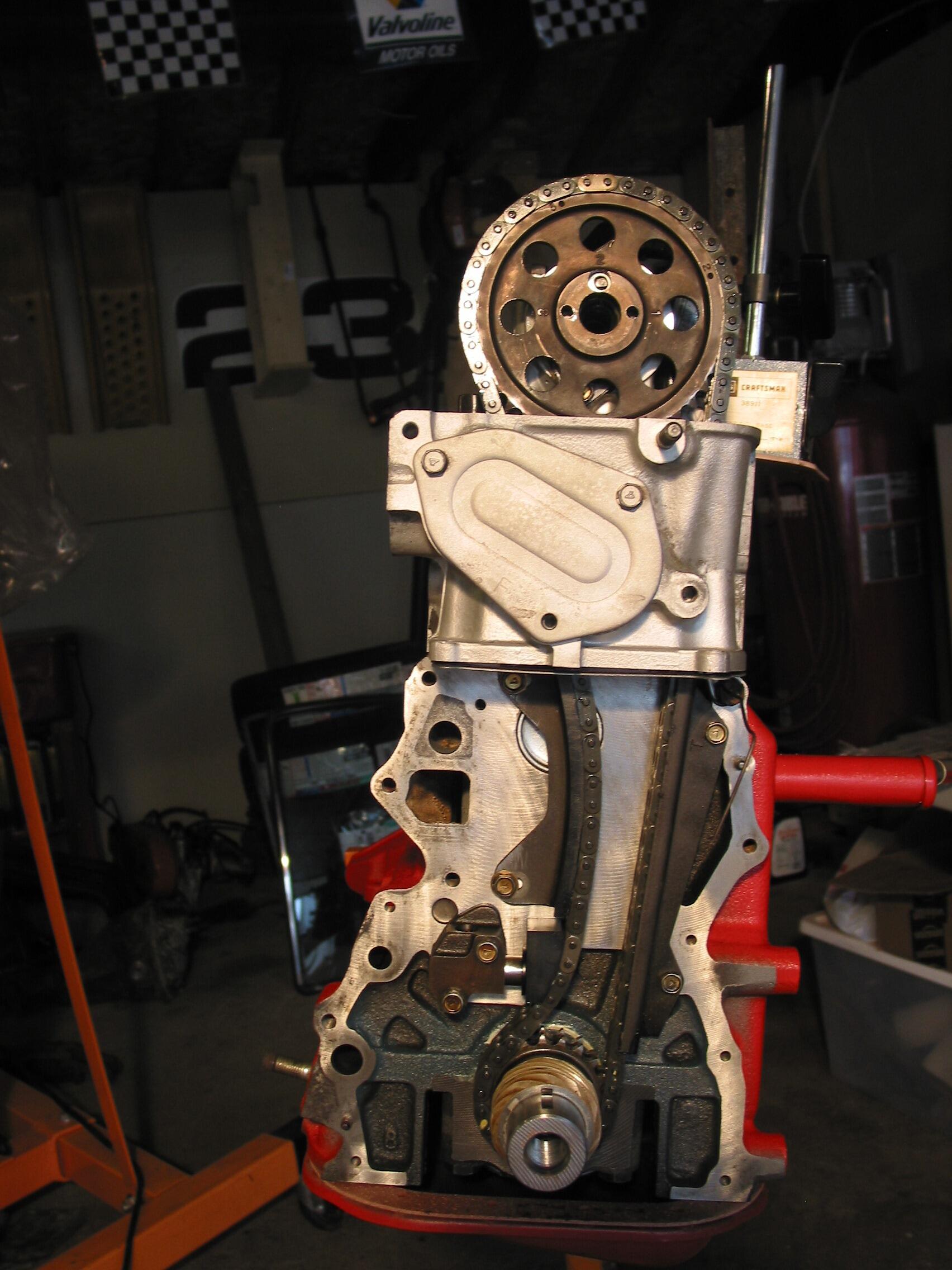
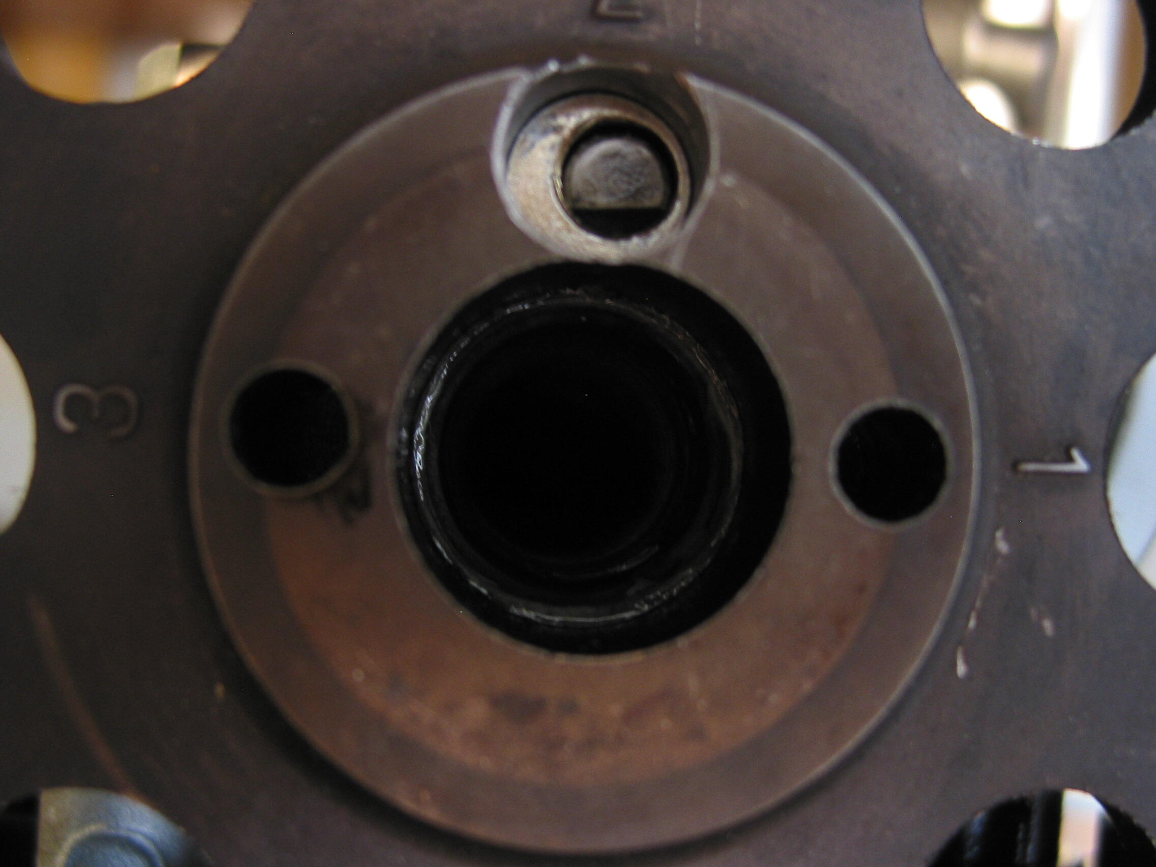
This should make you feel better. I found the picture of mine before I installed the new chain kit. Notice how much stick out I had. The only change was replacing the chain, gears, guides, and tensioner.
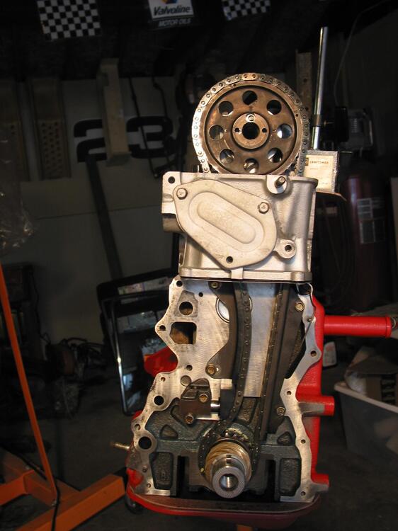 1 point
 -
I suppose I can do without it. Suppose it's just nice to have it. If I have trouble this time I'll definitely use a zip tie. Little update, called the machine shop and they said they removed only about 0.003-0.004 inch when shaving the head since mine was relatively straight and I didn't specify how much to remove so they removed as little as possible. Gives me a little more confidence my chain is just extremely stretched and a new one should solve it1 point
-
1 pointI believe this is what @dutchzcarguy is talking about: https://history-computer.com/what-is-a-flip-flop-in-electronics/ You have the output of the circuit going to a relay (coil). The contacts of the coil are in the circuit that go to the circuit you want to pulse. Just make sure the relay is rated for well above the max power of the circuit. You don't want to weld the contacts.1 point
-
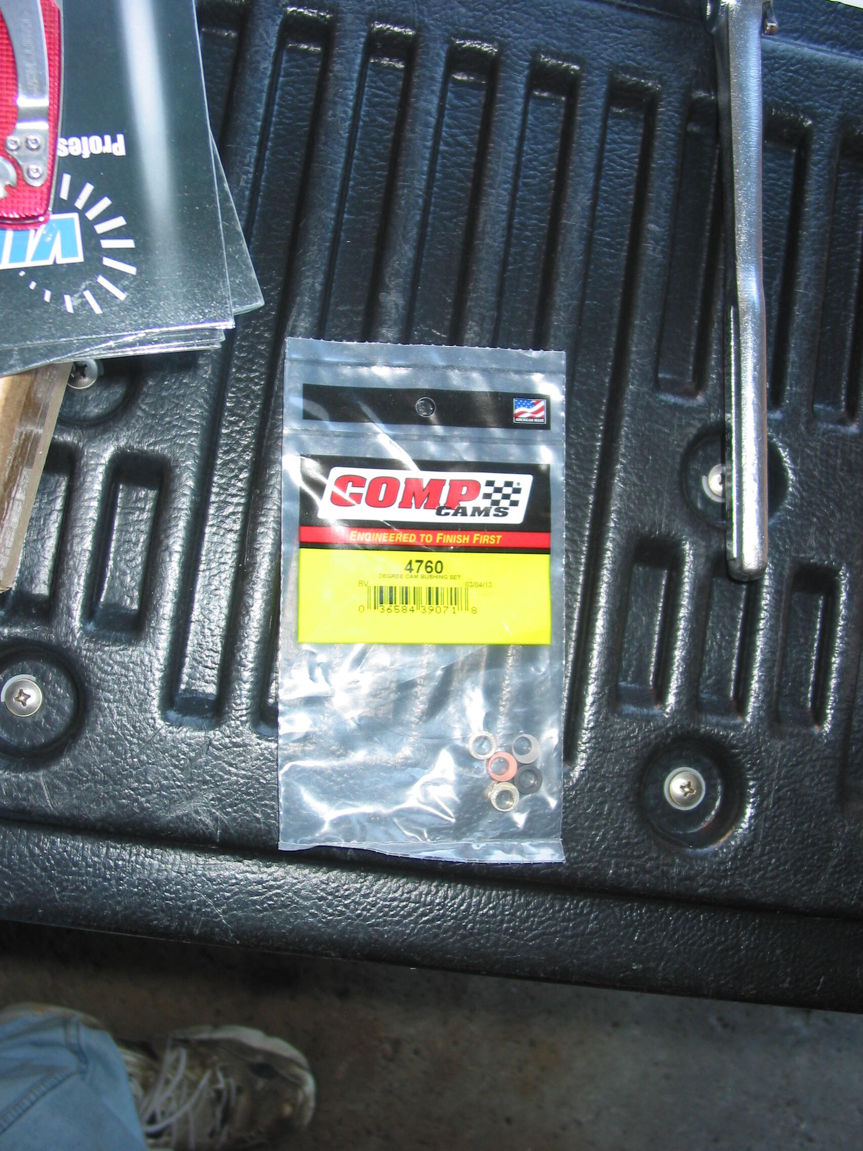
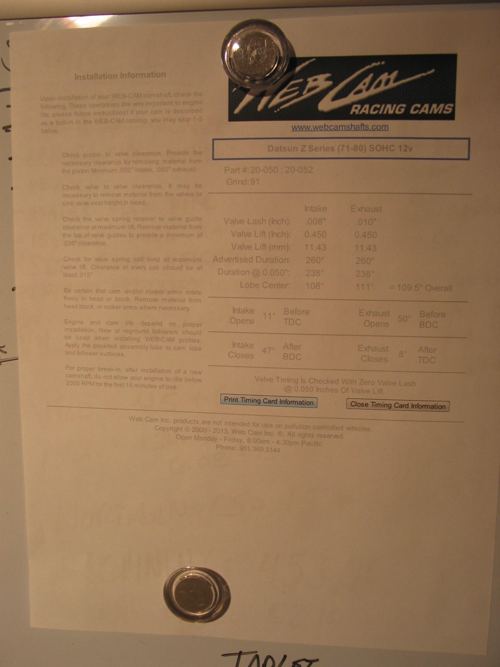
LOL. No spacers. P79 head shaved 0.050" on a F54 block and stock valves. I dialed in the Web Racing cam with a degree wheel an the GM bushings. The motor pulled hard to 7,000 RPM.


 1 point
 -
Something for the carb guys. https://bringatrailer.com/listing/mikuni-44phh-carburetors-and-intake/ . .
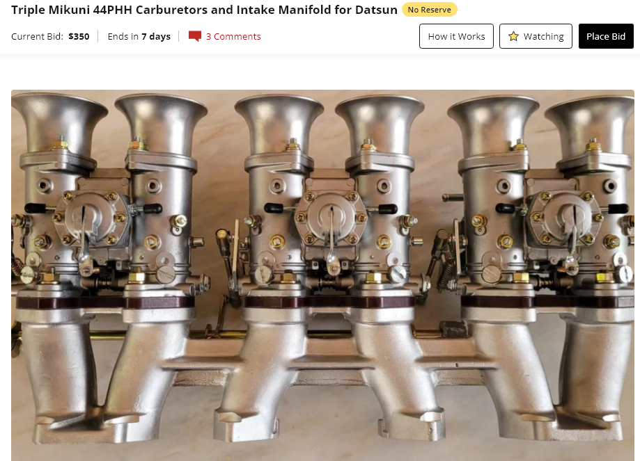 1 point