


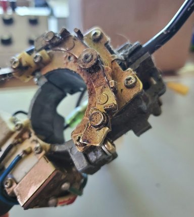
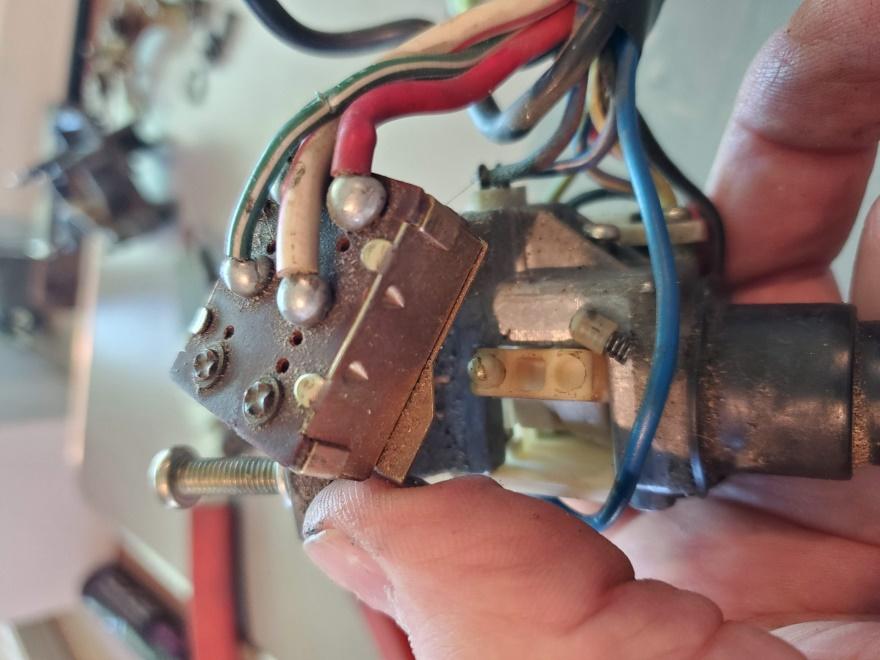
1976 280Z Combination Switch Teardown
Problems to be remedied:
1) The turn signal self – canceling pawls won’t return by their own spring force;
2) The turn signal lever is slow to return from the R or L position after being released;
3) The selector detents (headlights, signals, wipers) feel sticky and imprecise; and
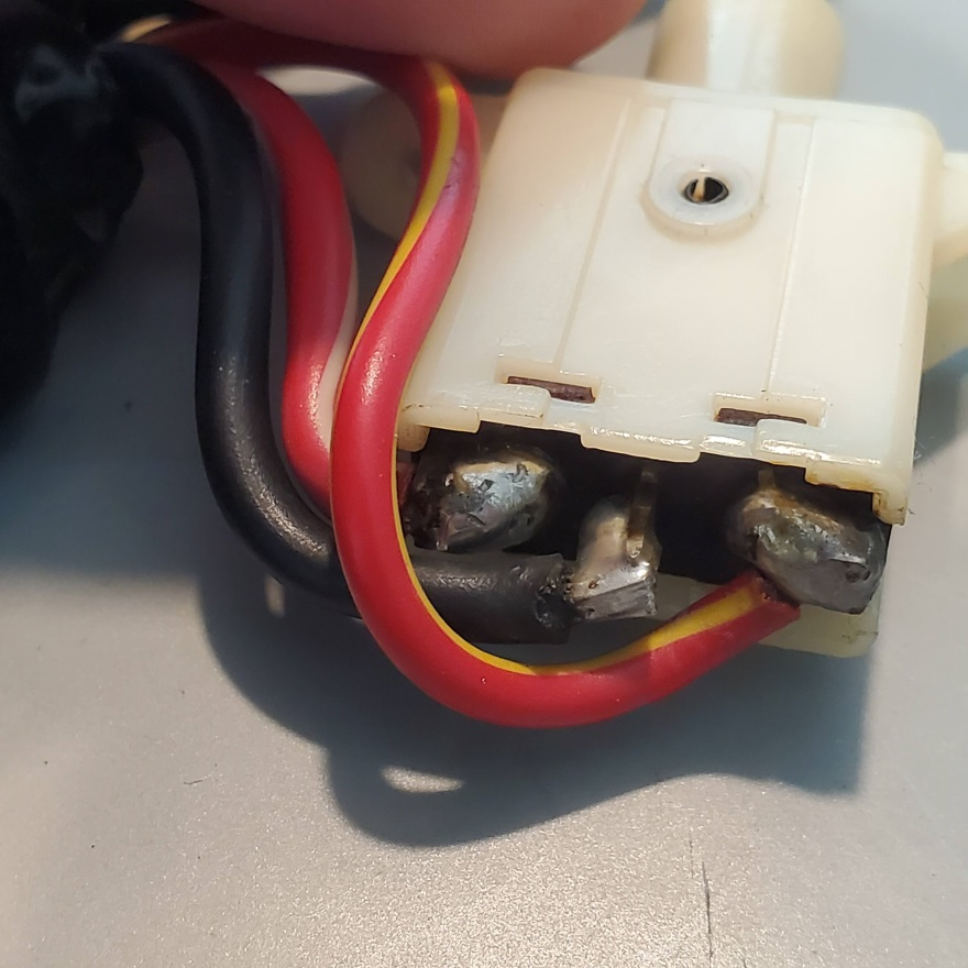
4) Headlight and turn signal switch contact resistance is high and inconsistent.
In addition to needing these repairs, I was concerned about the integrity of wire harness connectors, solder joints, switch contacts and springs, and wire insulation and wanted to perform a thorough inspection.
Pic 1
Pic 2
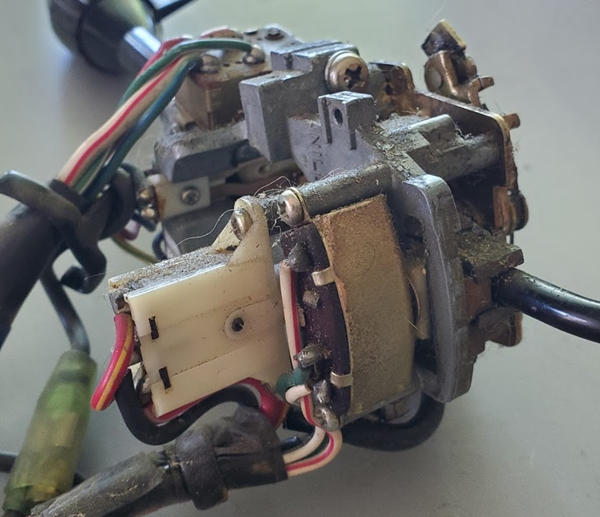
The teardown included every removable component as well as disassembly of the switches. I passed on taking apart the headlight high/low push-button type switch though. All the other switches were taken apart by either bending up the tabs on the metal back cases or removing screws to release the internal components. The high/low switch is a snap-together type and I did not want to risk breaking the plastic housing or the phenolic board that snaps into it.
The disassembly process for everything else is very straightforward – as everything is secured with phillips head screws.
After disassembly, all the mechanical parts were cleaned in mineral spirits which very quickly dissolved the hardened grease and oil but not enough to obviate needing a toothbrush. After drying, a careful application of fresh grease and oil, where appropriate, made everything work like it should.
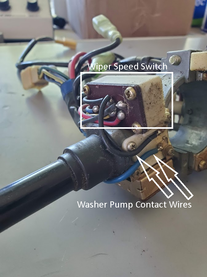
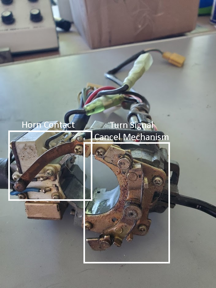
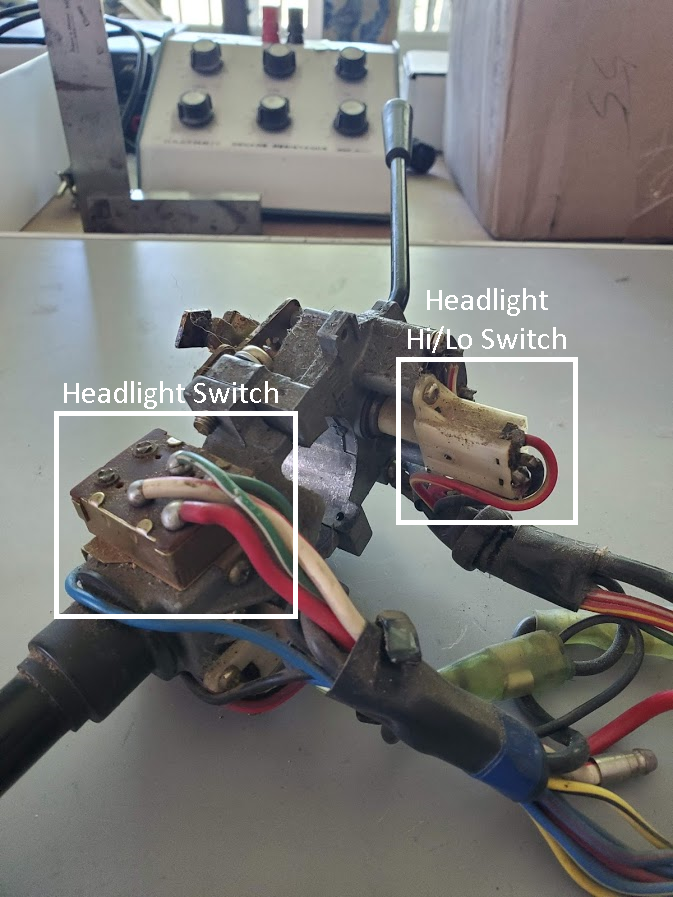
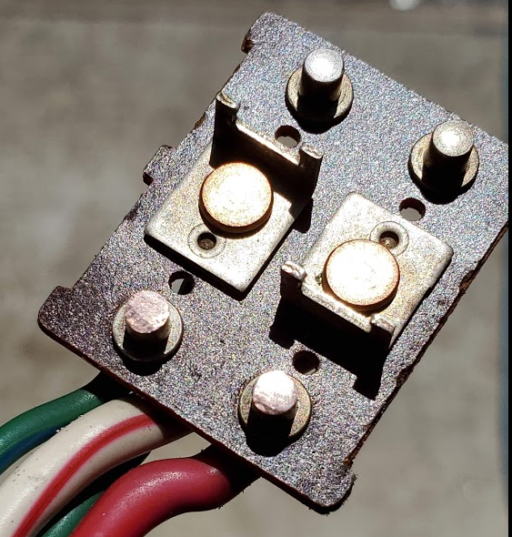
Switch Identification
Pic 3
Pic 4
Pic 5
TEARDOWN
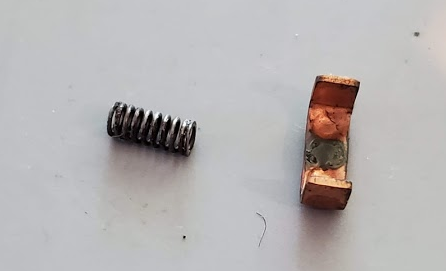
Take care to keep the springs with the bits they belong to. Although most appear to be the same, there are differences in diameter and spring rate.
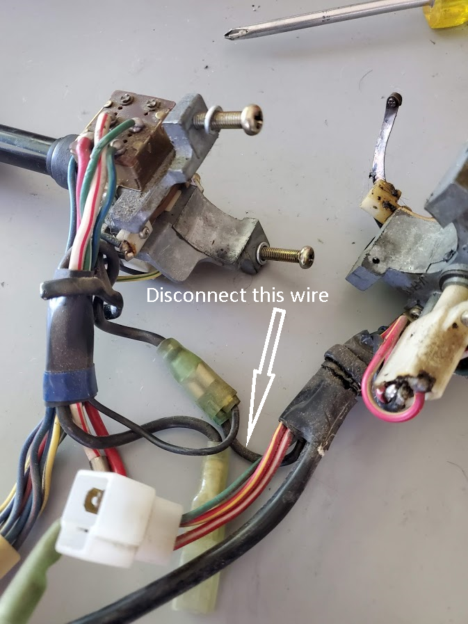
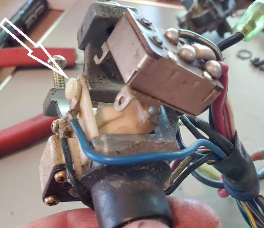
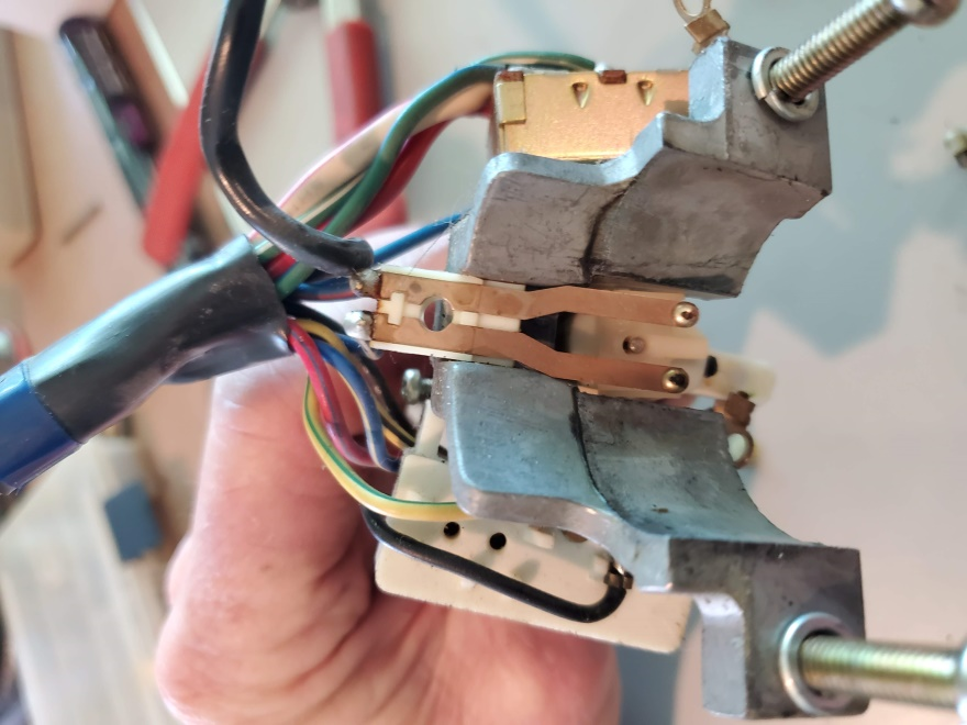
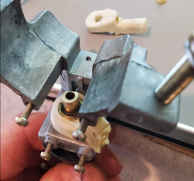
Separate the two halves of the assembly and disconnect the bullet connector that electrically links the two halves:
Pic 6
Remove the screws securing the wire right side wire retainer. Note the retainer passes between the washer pump wires:
Pic 7
Reassembly Note: The left side wire retainer goes to the bottom notch. The top notch is just visible in the extreme lower left corner:
Pic 8
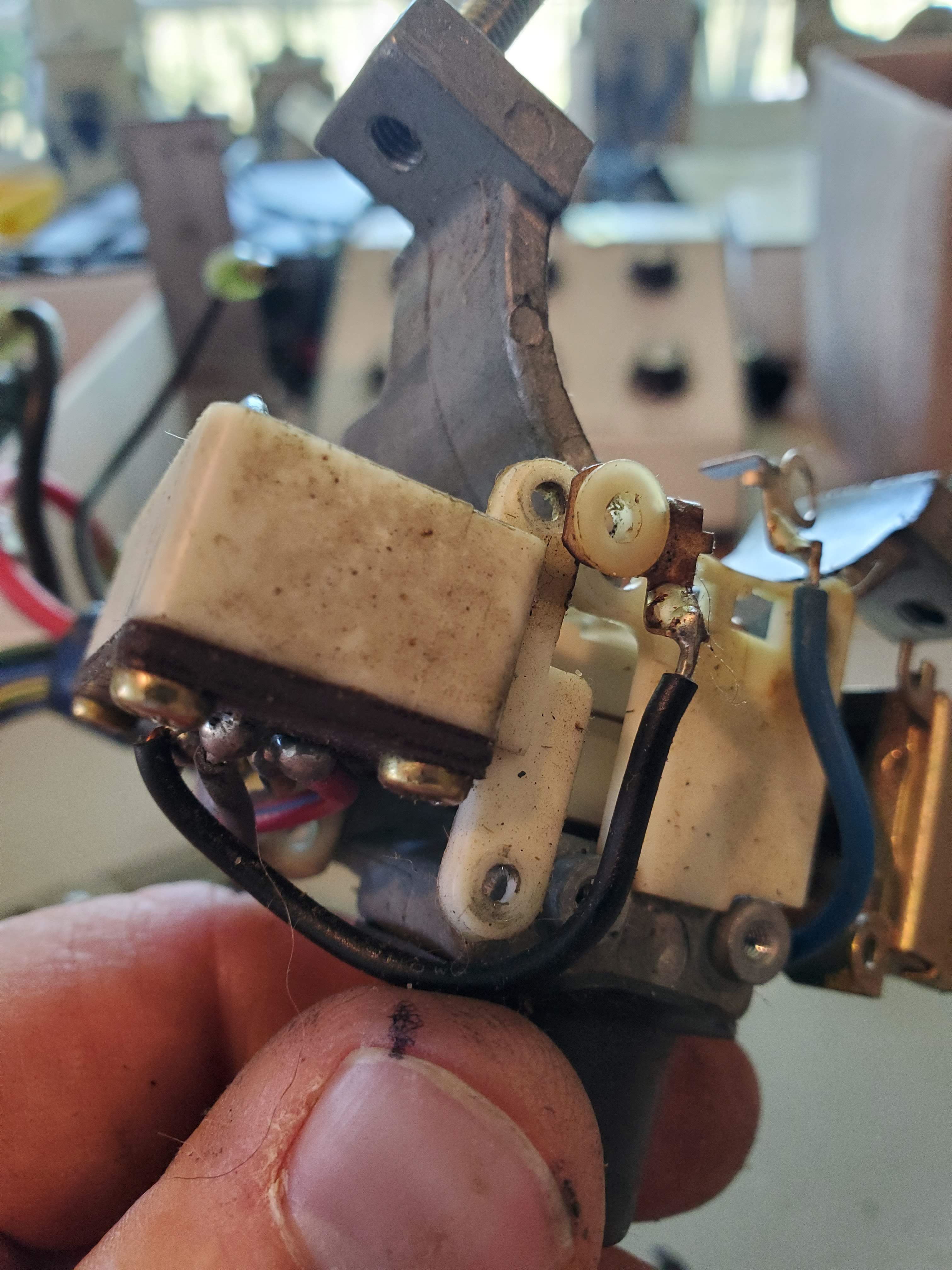
Remove the (3) headlight switch screws. Doing so will release one washer pump contact. As you lift the switch, keep track of the (2) spring-loaded plungers beneath it and the nylon shoulder washer that insulates the washer pump contact from the screw securing it (Pic 10):
Pic 9
Pic 10
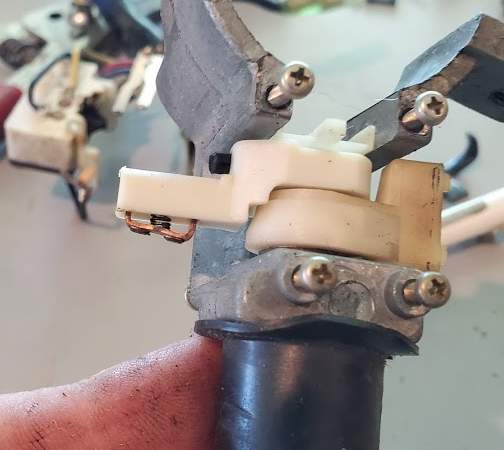
Remove the (3) screws from the wiper speed switch. Doing so will release the other washer pump contact with its shoulder washer. Remove the sliding contact and spring, as well as the black detent pin and spring:
Pic 11
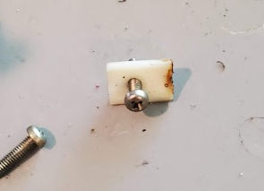
Remove the (1) screw holding the washer pump contacts and (2) pieces of plastic that sandwich them:
Pic 15
If you do not intend to disassemble the hi/lo switch, the wire retainer for that switch and the turn signal switch can remain attached to the wiring on that side. Remove the (2) screws holding the turn signal switch and the (2) screws holding the high/low switch:
Pic 17

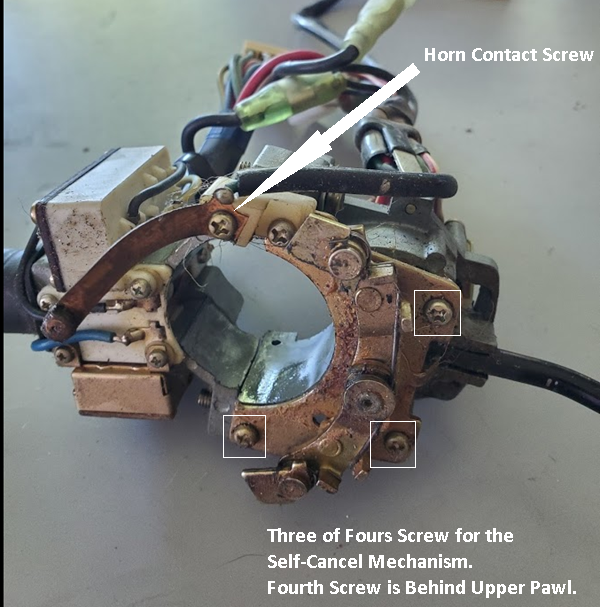
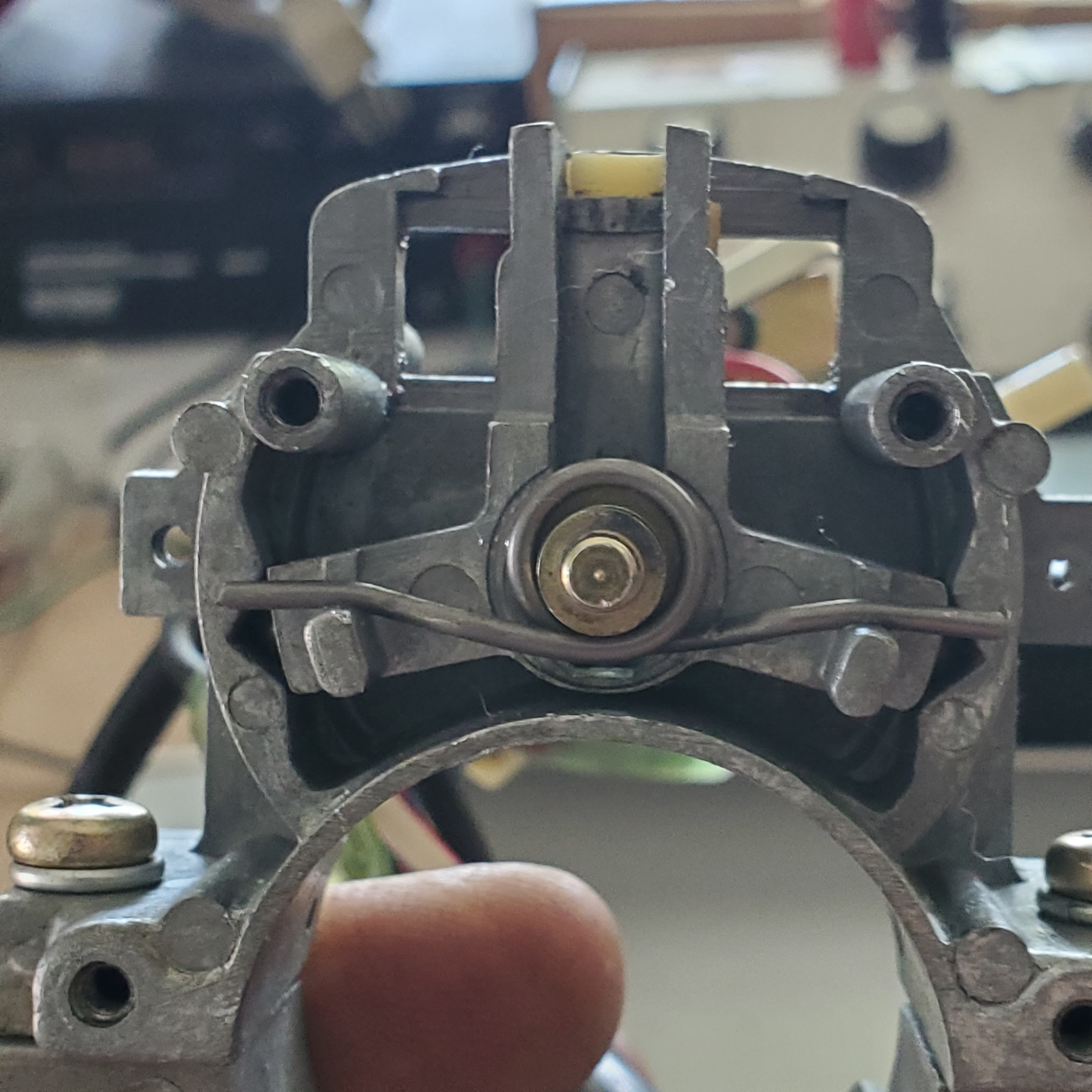
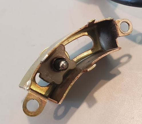
Remove the (1) screw holding the horn contact to its white plastic base, then remove the (4) screws for the self-cancel mechanism. Note that both pawls are out of position:
Pic 18
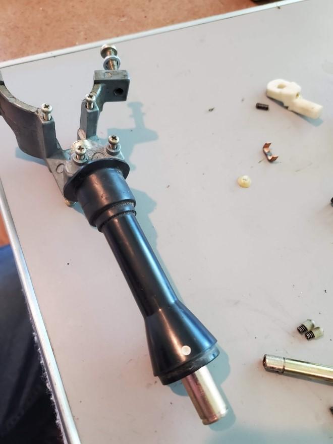
It isn’t absolutely necessary to disassemble the right hand stalk (with the headlight, wiper, and washer switch controls) in order to deal with the problems described at the top of this thread. That said, let’s dig in.
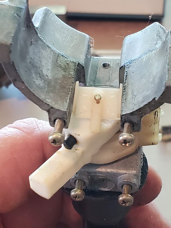
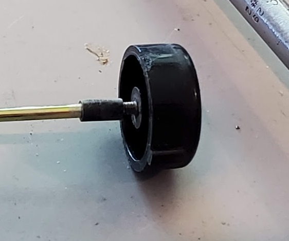
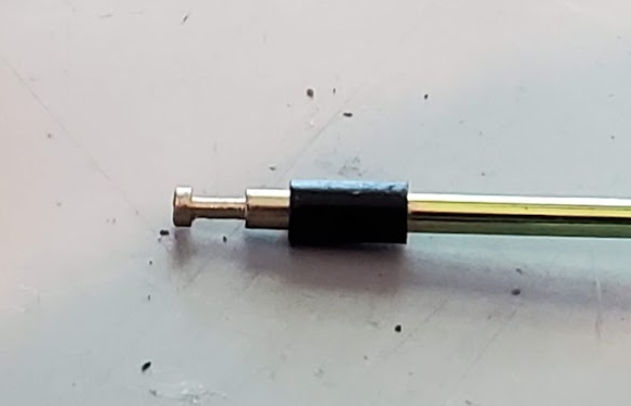
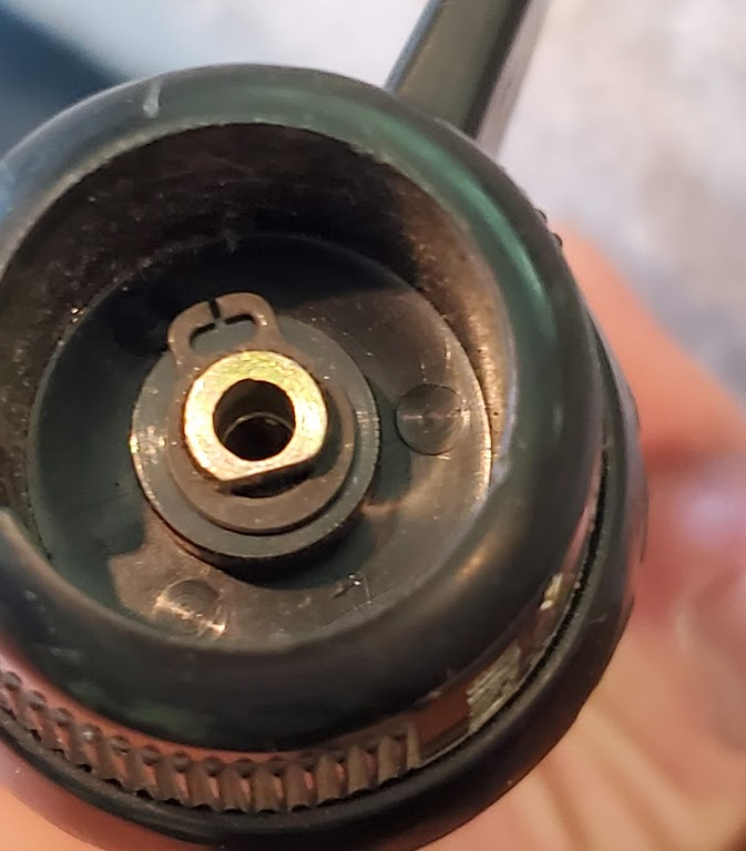
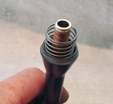
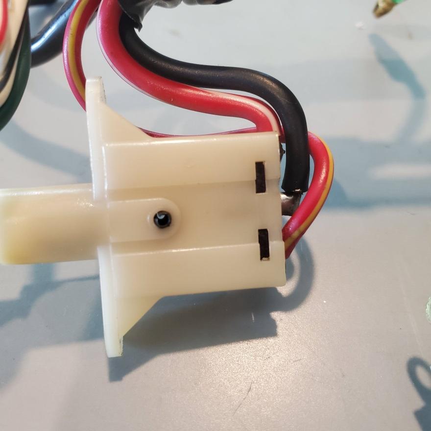
Remove the washer pump actuator rod by depressing the washer pump button and disengaging the white plastic retainer from the head of the rod. The rod will easily slide out. The plastic bushing on the small end may fall off the rod when it’s withdrawn from the stalk. They appear to serve to keep the rod centered in the bore:
Pic 19
Pic 20
Pic 21
Remove the white plastic wiper switch actuator arm (friction fit on shaft) (in the background), and then the retaining ring beneath it that secures the headlight switch actuator arm:
Pic 22
At the opposite of the stalk, remove controls by removing the retaining ring:
Pic 23
Pic 24
Slide the black sleeve off the shaft to expose the c-clip:
Pic 25
Pic 26
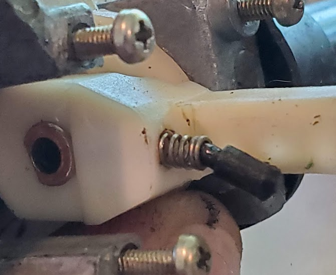
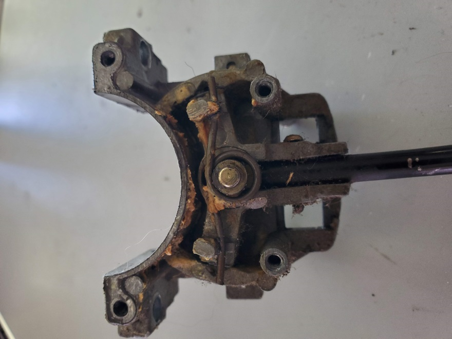
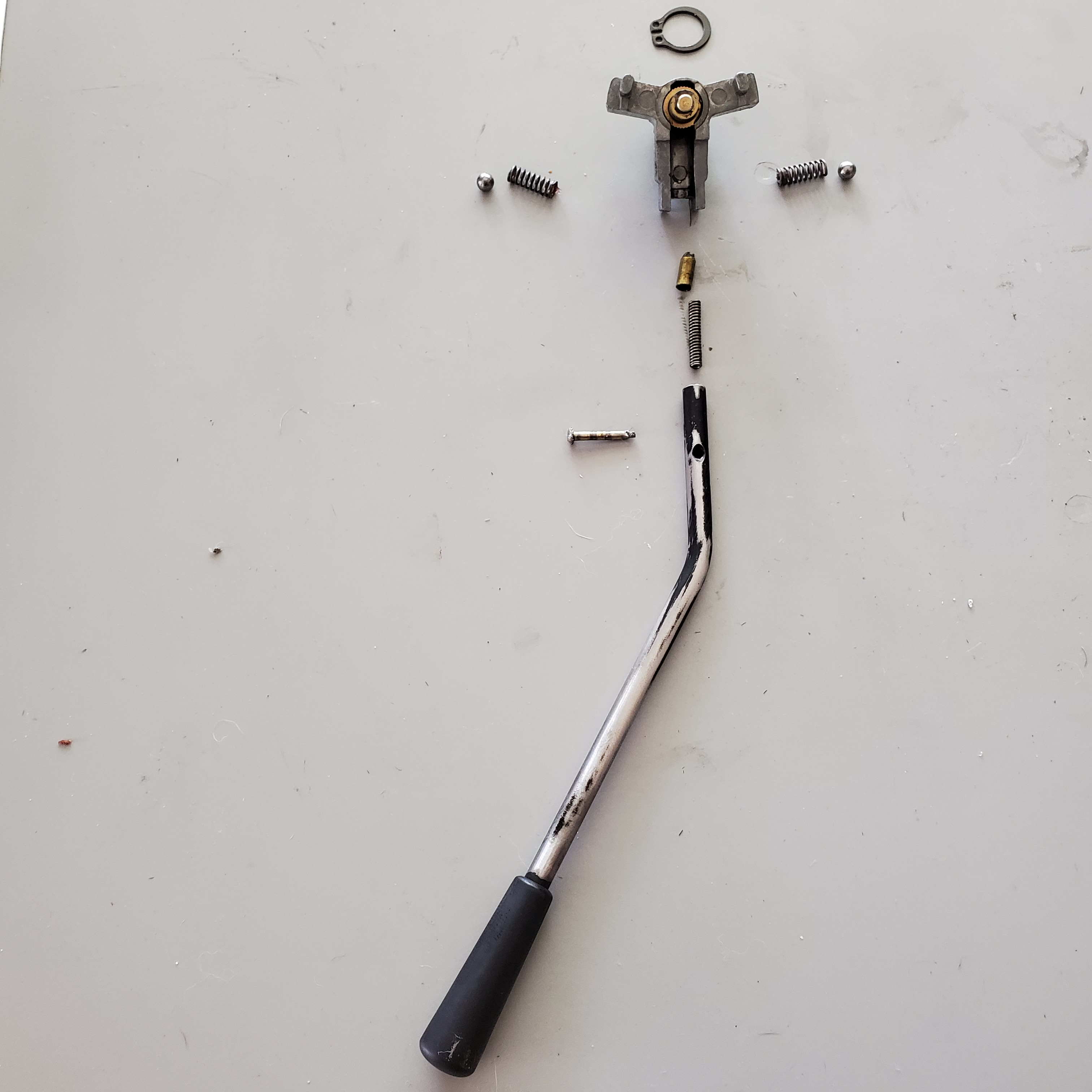
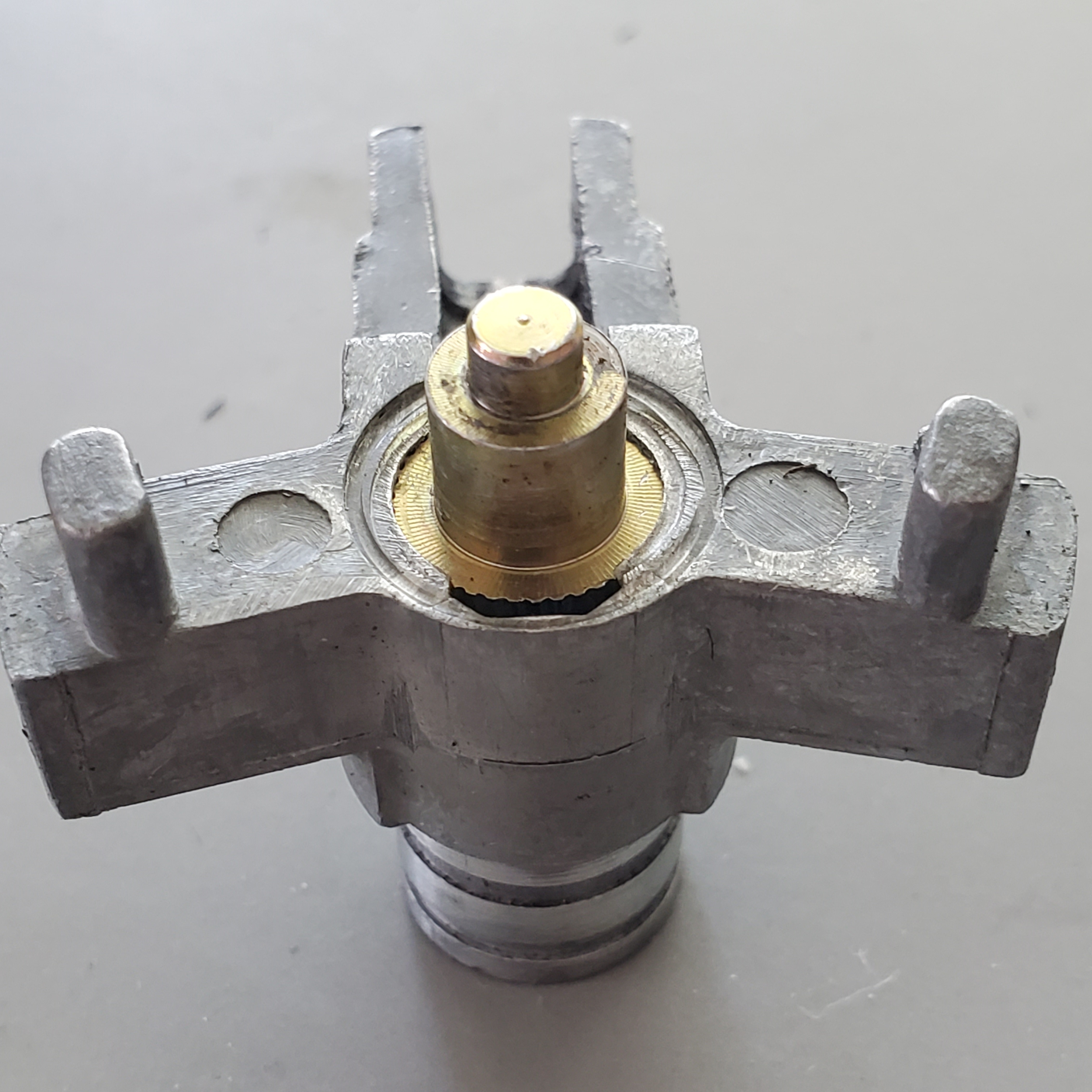
On the left side assembly, after removing the self-cancel mechanism, remove the torsion spring. Then, on the reverse side, remove the retaining ring to free the turn signal actuator block, and then the sliding white plastic block. Once removed the detent balls and springs can be extracted (take care to catch them as you pull out the actuator block):
Pic 27
Pic 28

Pic 29
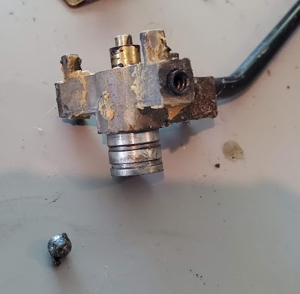
Unfortunately, the pin that retains the turn signal lever is swaged on the end opposite the round head. The only way to remove it is to cut if off or try to make it round enough to get through the hole in the block, which is what I did. I figured I’d just make a new one on the lathe. The problem of course is how to swage the end again so it’s flat.
Pic 30
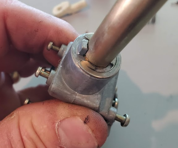
The block, which appears to be a zinc die-cast type part, holds the upper pivot and spring post, which is a brass serrated pin, by means of swaging the zinc shoulders around it. This one is very loose, but there is no damage. It’s just the zinc deforming over time from the barrel of the torsion spring bearing against it. There is very little zinc base area below this pin and less above it (to clamp it in place). I could see no good way to reinforce or otherwise add something to improve the retention force, so I used a socket that fit well and put it on the press – gently. The brass pin tightened right up, but I doubt it will stay that way long. I really wanted to silver solder it or something, but fear of catastrophic failure made me think otherwise.
Pic 31

Pic 32
Pic 33
While it’s all apart, it’d be a good time to repaint the lever and polish out small scratches in the plastic knob (wet sanding with 400, 600, and up worked well).
SWITCH DISASSEMBLY
Wiper Speed Switch
Remove the (3) screws to expose the contacts. Be very careful with the thin phenolic spacer. Its thickness matches that of the fixed contacts and prevents the sliding contact from getting hung up on the edges:
Pic 34

I did not remove this rivet to gain access to the wiper motor contacts, as I had no way to safely replace it:
Pic 35

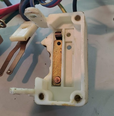
Headlight Switch
Bend up the tabs on the metal case to release the phenolic contact board. Do not straighten them, just move them enough to free the board. Every time the metal bends it work hardens. When you reassemble the switch, the tabs will not want to bend back exactly the way they were. Also, should it be necessary to open the switch again, the tabs could break from being hardened. Note the evidence of contact arcing inside the case:
Pic 36
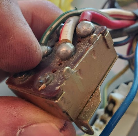
Pic 37
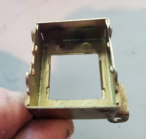
Pic 38
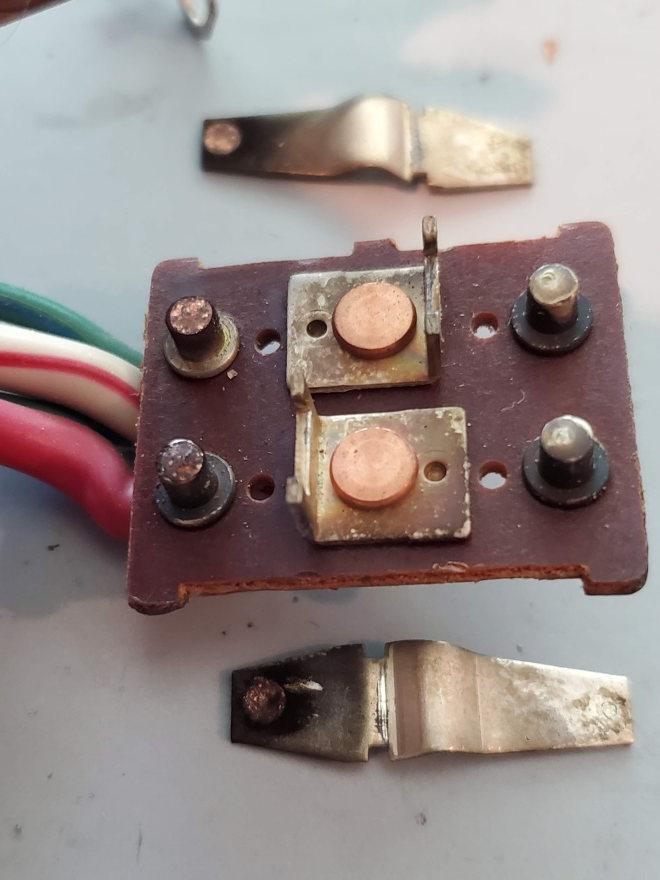
Pic 39
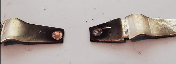
The contacts have suffered some pretty good erosion and cannot be easily repaired. My solution was to simply reverse them from one side of the switch plate to the other to permit the untouched ends to make with the posts on the board. It might also be wise to consider adding a pair of arc-suppression diodes to this circuit (and perhaps to all the contact sets showing similar evidence of arcing):
Pic 40
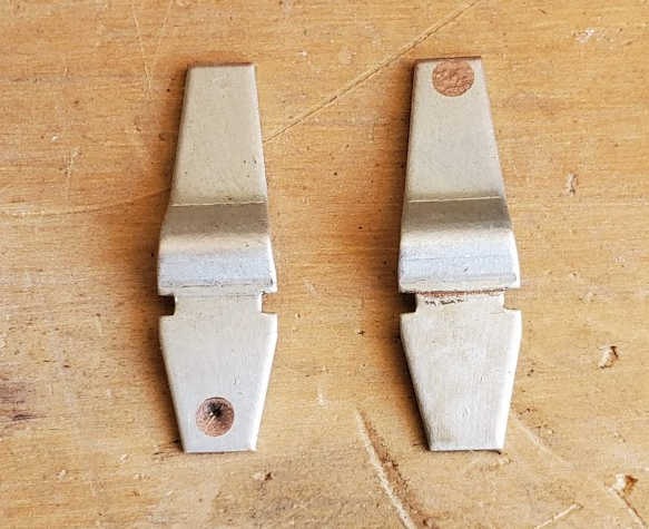
Pic 41
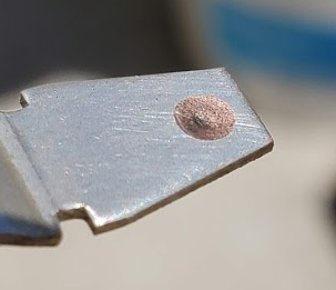
Pic 42
Turn Signal Switch
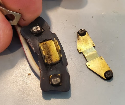
Same process as for the headlight switch. Bend up (3) tabs. Inside the case is a actuator plunger and spring, and a moveable contact. Contact erosion was minimal and they were freshened up quickly:
Pic 43
Pic 44
High/Low Headlight Switch
Because this switch is assembled by snapping the contact board into recesses in the switch housing, I decided not to attempt disassembly out of concern for either part breaking. If it ever fails, then I have nothing to lose by attempting a repair:
Pic 45
Pic 46
Reassembly Notes
As mentioned above, overworking the tabs can cause problems. The first pic is what you might get if you are not careful with re-bending the tabs. Notice how the contact board does not sit flush to the outside of the case. It’s because the tabs do not easily bend where they originally did and are now bending lower, toward the case. The remedy is to gently work the tabs so they are not pushing sideways against the board. The second pic is after tuning them:
Pic 47

Pic 48
The washer pump contacts are held in place sandwiched between two white plastic parts, the one shown below in Pic 45 and the one shown in Pic 16. The bosses indicated by red arrows below mate with matching female recesses in the other part.
Pic 49
If you have any plastic bits showing some distress, consider setting the retaining screw(s) gently and applying some blue Loctite, as opposed to cranking down on them which could invite a bigger problem.
Pic 50

Recommended Comments
Create an account or sign in to comment
You need to be a member in order to leave a comment
Create an account
Sign up for a new account in our community. It's easy!
Register a new accountSign in
Already have an account? Sign in here.
Sign In Now