


240260280z
Free Member
-
Joined
-
Last visited
Everything posted by 240260280z
-
 Glad to help out. You can read and see pics here:http://atlanticz.ca/zclub/techtips/suspension.htm
 -
That is the 260/280 kit. If you have a 240z most of it will work but some items need to be trimmed. I would recommend that you also buy the ball and socket tension-compression rod kit rather than use the poly parts in the kit.
-
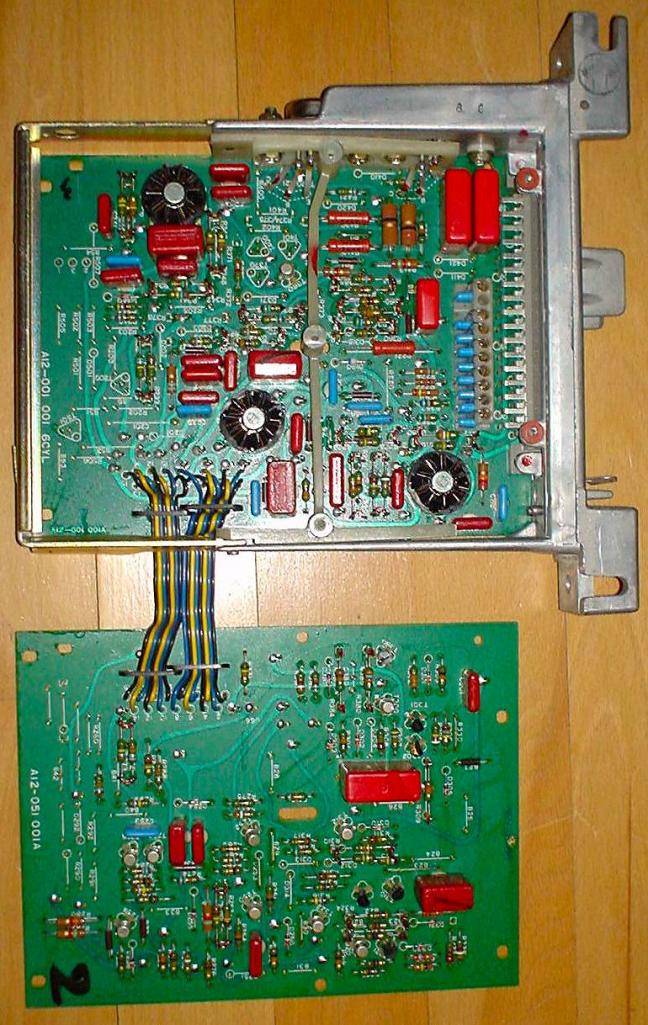
The injector driver transistors can be seen near the top of the circuit board photo. They are thermally connected to the ECU frame for cooling.
-
You have to make sure the needle valves in the fuel bowls are functioning. You also have to make sure the return line to the tank from the fuel rail is connected. The stock fuel pressure is ~ 3.5 to4.5psi so if your pump is putting out 7psi, it may overwhelm the old needles...especially if the return line is blocked off. Did you see fuel squirting before the fire? Try disconnecting the low voltage to the coil/ballast (to stop spark) and crank the car and watch for fuel leaks.
-
The connecting rod is threaded at the end making it adjustable. You may have to loosen the lock nut and turn the rod in or out to correctly set up the system. Read the factory service manual for details of the floor to pedal distance and so-called "free play".
-
My dad told me this advice "There millions of cars out there and there are always great cars to buy at great prices, be patient and wait....it will happen over and over again". This is especially true for Calif!
-
More EFI docs from my HD BOSCH L-Jetronic Injection Manual.pdf 280zfuelinjectionbook.pdf
-
Lots of EFI info in the PDF's below. 280zfuelinjectionbook.pdf h22.pdf BMW EFI PPT.pdf Porsche 912 EFI.pdf h21.pdf efi_injectorservparts.pdf
-
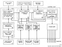
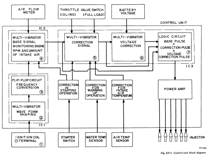
In theory, individually synchronized injector events seems to be the ideal but from what I recall reading online, it does not seem to matter much...especially at high rpms. Here is the most detailed circuit info I have (from 75 280z manual's EF section)....sorry no board artwork or detailed schematics seem to be in the public domain.

-
CHECK OUT THE PDF BELOW NTB94-097 (Nissan ECU Guide).pdf
-
I can't find a schematic but here is a crude diagram and some geeky probing here:http://www.205gti.com/bosch/mods.htm
-
Popping through the exhaust is usually rich and popping through the intake is usually lean (or very bad spark scatter or improper timing or plug wire mix up).
-
Here is a pressure differential switch to get you in the zone:
-
If you are out of luck, maybe - clean up yours in a sink full of hot soapy water and a tooth brush. - let dry - bend back into shape - "paint" the outside with the "plasti dip" goopy stuff to seal
-
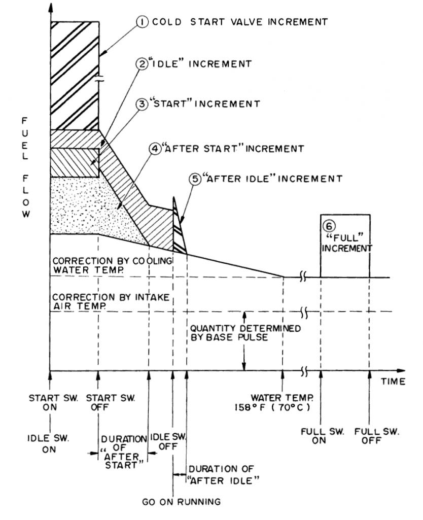
I looked at a 280z ECU many years ago and all I recall are transistors being the only silicon stuff. The circuit is basically a waveform shaper whose input is a timing "pulse". It generates a waveform of PWM square wave that is basically the duty cycle of the fuel injector... a longer "on time"/Puslewidth causes a longer squirt of the injector. There are additional inputs to a voltage to pulse-width summing circuit that add to the base width of a pulse to compensate for engine temp, air temp, WOT/Idle at TVS etc. There is also a logic circuit for fuel cut off when coasting with foot off the pedal.... I'll try to dig up some more details....maybe even a circuit diagram. Here is an intro to the system I wrote many moons ago: http://atlanticz.ca/zclub/techtips/efisystem/overview.html
Could the popping be "knock" and you are advancing too quickly?
I have read many reports (including dyno data and mileage data) that newer EFI systems are capable of more fuel efficient operation and also capable of drawing more power from the engine than carbs and the stock EFI system. The stock system is "good" ..... especially relative to 1976.
Try a slow acceleration from 1000rpm on a flat stretch in 1st then 2nd then 3rd gear to see exactly where the popping occurs. The damping oil should only affect: 1. throttle transitions due to pedal 2. engine vibration/road bumps 3. engine rpm changes from gear changes If you do the test above you will rule out the oil viscosity.
looks normal. This was mine:
When I first measured H (14-15mm for early su's) it appeared that the aluminum swing arm which holds the float is parallel to the roof of the float bowl. Now when I set the tang I just hold the assembly upside down and swing the float until it is parallel with the base and watch where the tang just touches the needle valve. This is a quick and dirty method. The most accurate method is to: 1. bleed fuel from float bowl 2. remove domes 3. crank starter to run mechanical pump fuel (or electrical) and allow bowl to fill naturally 4. measure fuel depth in jet using "optical dip stick" (acrylic rod with two flush ends...when the rod is lowered and one end hits the fuel, the other end darkens) 5. repeat and adjust tang until fuel is ~10mm below the top of the bridge
Happy 2012....have a dynamo time.
Welcome and good luck! All of us here on the site are standing-by to give assistance, guidance, support and wisdom when ever you need it! Don't be shy.... and post somepics of your new baby.
Hey, what about all the high fructose corn syrup in all the food too.... the corn growers sure can lobby! Next they will be mandating corn-iron alloys.
Important Information
By using this site, you agree to our Privacy Policy and Guidelines. We have placed cookies on your device to help make this website better. You can adjust your cookie settings, otherwise we'll assume you're okay to continue.