inline6
 Subscriber
-
Joined
-
Last visited
-
Currently
Viewing Topic: Z's on BAT and other places collection
Everything posted by inline6
-
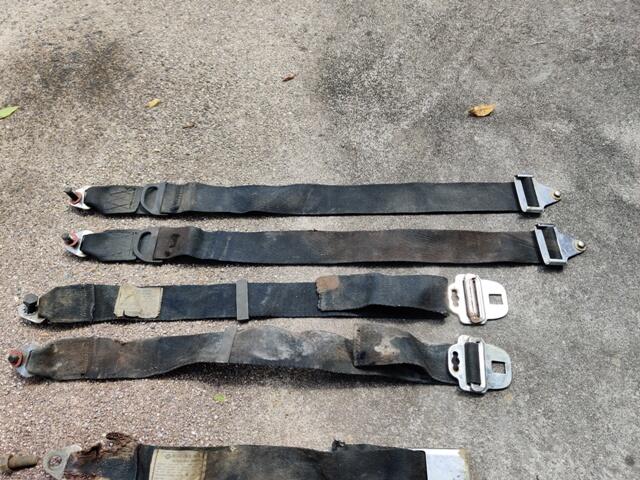
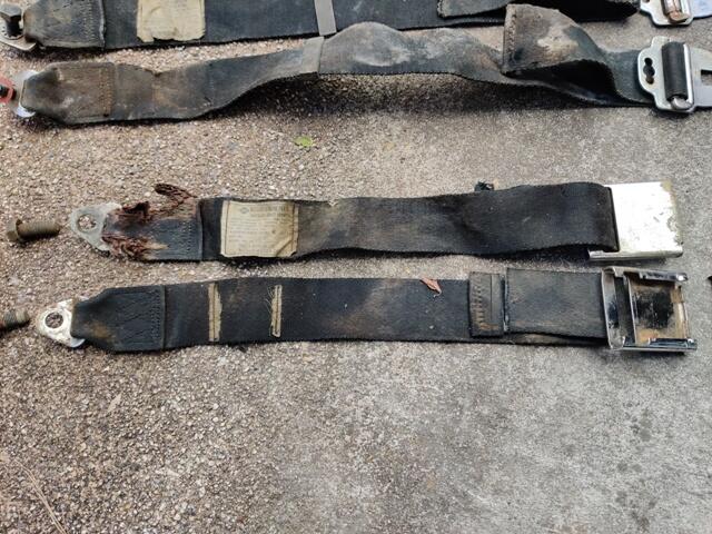
 Thanks for the info and pics. I found it odd that the parts book doesn't have the correct info for seat belts for my car. Here are pictures of my belts before I sent them off to have them redone: The original tags with lot numbers and date of manufacture were on two of the 6 belts. The buckle is the push button type. And the tab portion on the lap belt works with the "later" style shoulder belts.
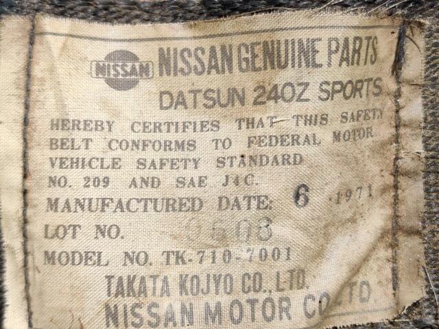
-
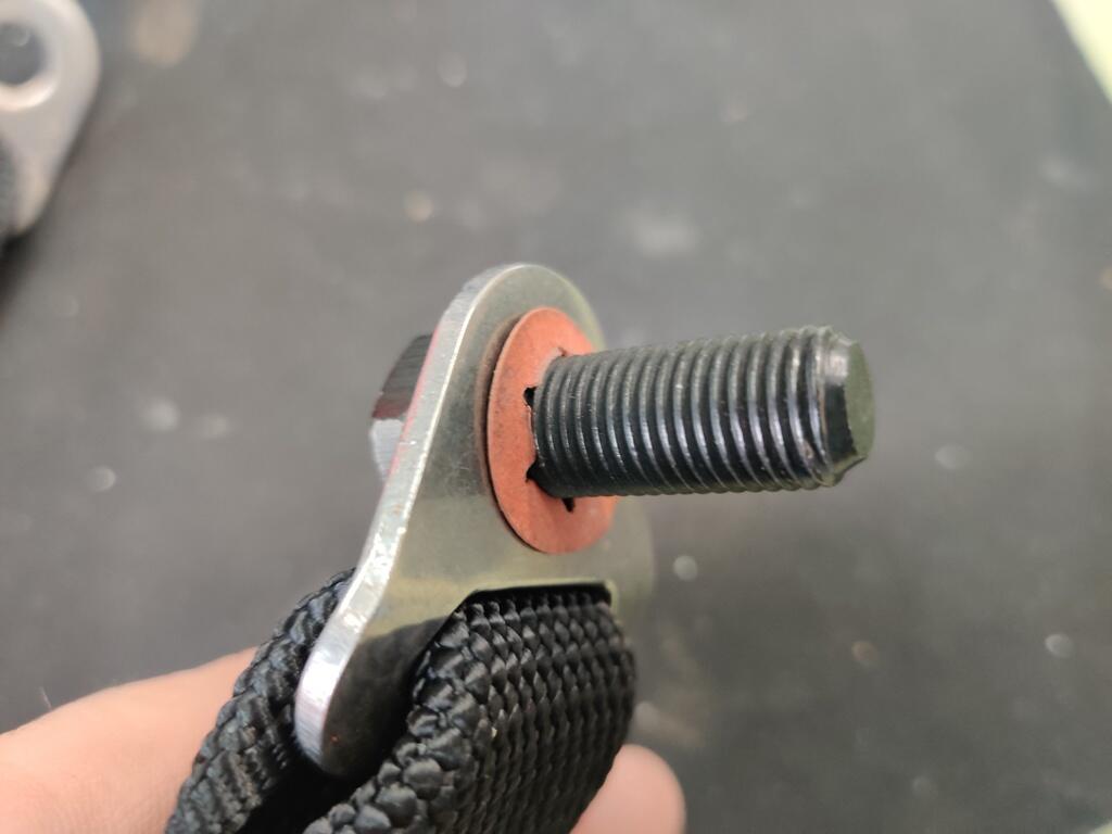
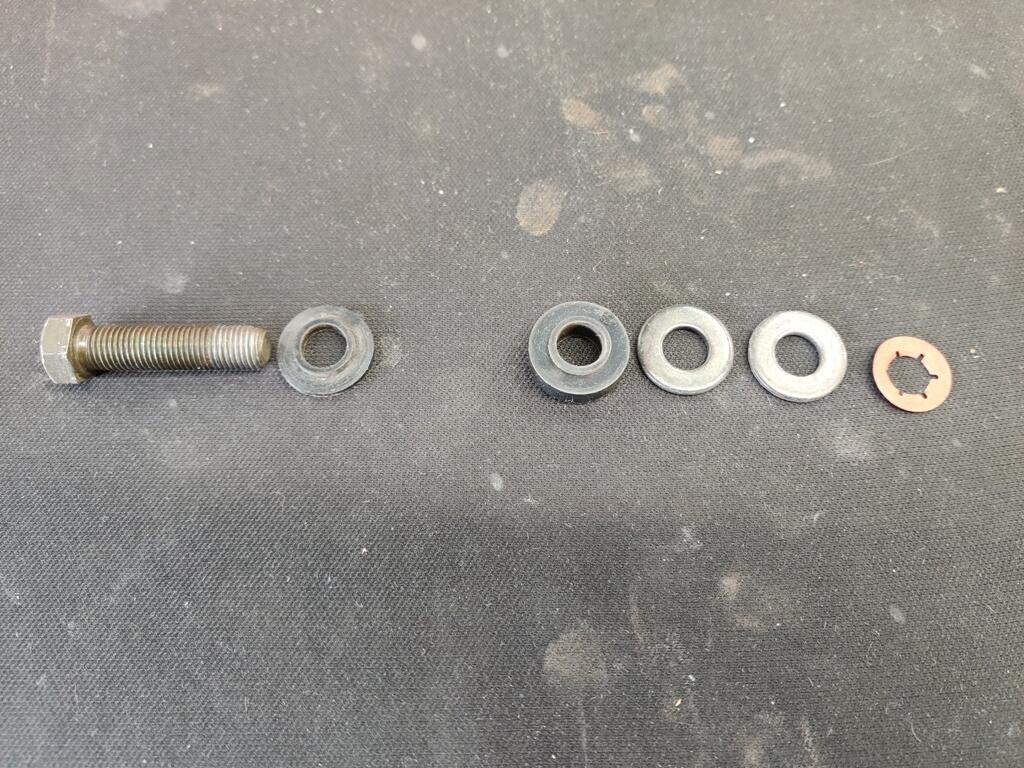
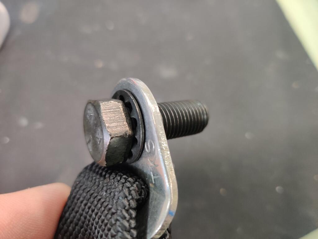
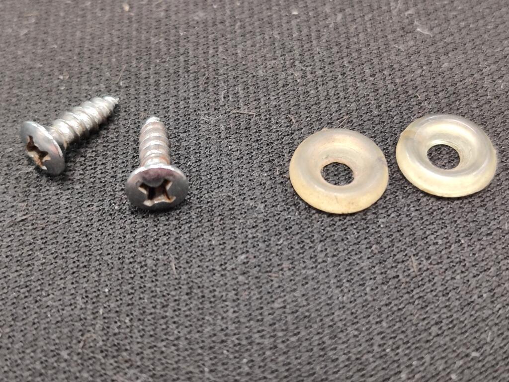
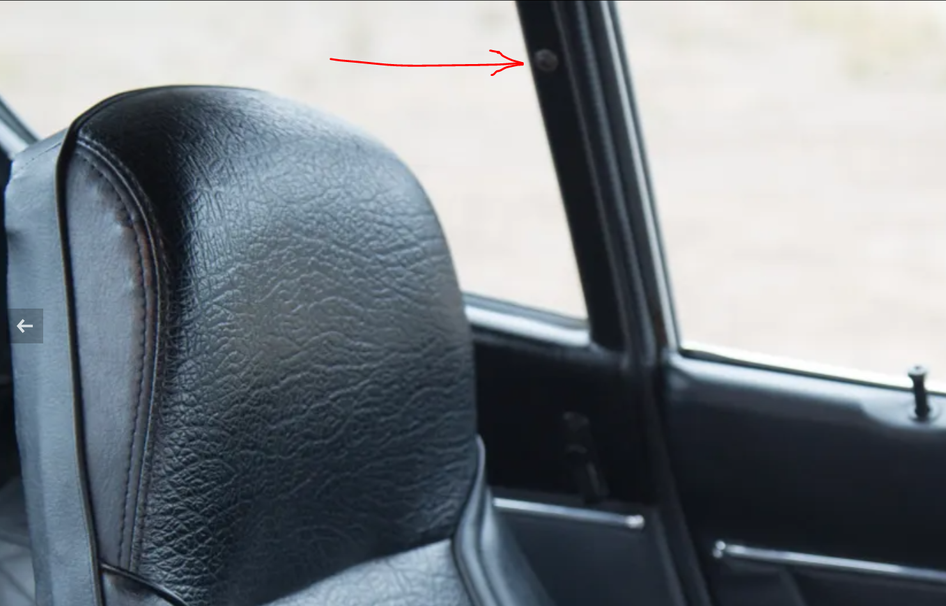
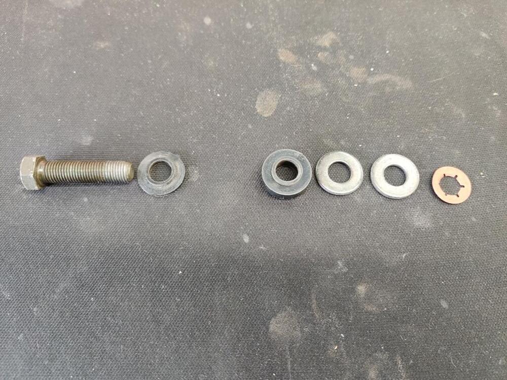
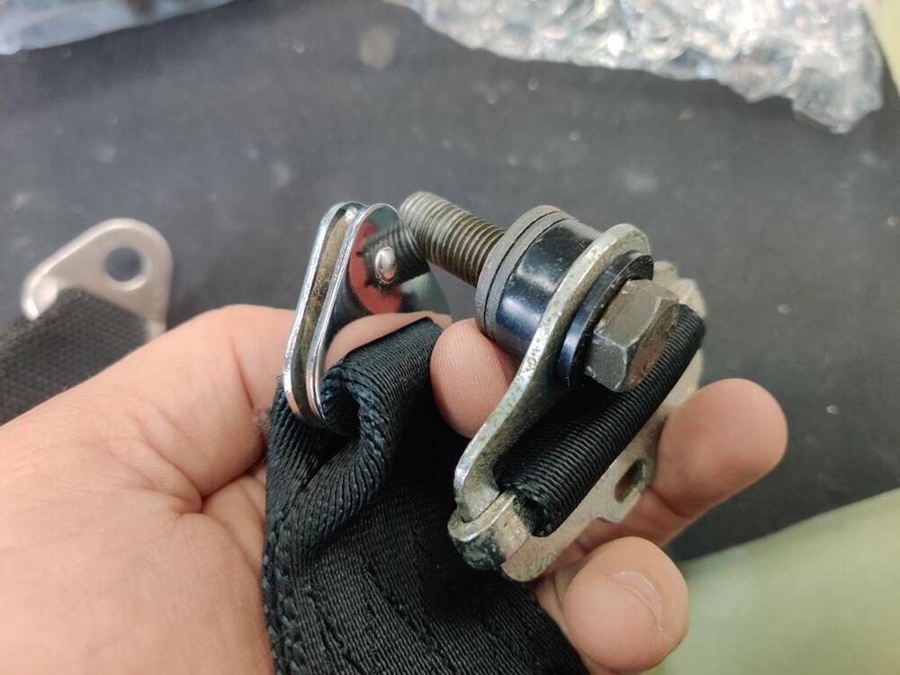
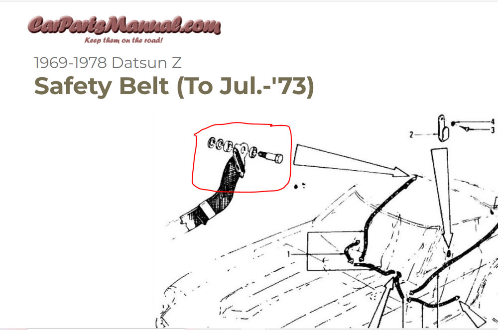
I am trying to determine what hardware was originally used at each anchor point for the seat belts in my 6/71 car. I think the lap bolts just used a bolt, a serrated washer, and a paper washer as shown in these two pictures: I happen to have a couple of sets of "early" seat belts (one set is 10/70), and this hardware was at the shoulder belt anchor. From left to right, longer than usual bolt, thin (relatively) plastic washer with raised shoulder, thick (relative to the thin one) plastic washer with raised shoulder, black metal washer, black metal washer, red paper washer. This hardware seems to match perfectly the parts schematic: The belt anchor goes in between the two plastic washers like so: The shoulders butt up against each other, allowing the anchor to rotate easily even the bolt is torqued down tight in the car. The anchor for the 6/71 shoulder belt is a different part/design than the early belt. This hardware will not fit the 1971 shoulder belt, as the 1971 anchor is much smaller. It does not accommodate the large diameter of the plastic washers. Does anyone with a 2/71 through 1973 car have original hardware in their shoulder bolt location? Could you share details of what is there?


-
A new video is available to watch. Making a new ball for the front ball joint - wow!
-
If I recall correctly, I made one by buying 1/2" round, aluminum bar from Home Depot, cutting to length and using a hack saw and hand held belt sander to make the drive end. Probably 20 minutes of work to make it. Check the 1/2" dimension before buying it though - pulling that from memory.
-
Yes, thanks for the info. I really appreciate it. Like most things with these cars at this point in time, the cost can vary wildly from shop to shop, and it depends on the actual work performed, obviously. My car was about as rust free as you can find, but even so, I found rust damage I wouldn't want to leave unaddressed inside the rear most part of the rocker panels where the quarter panel folds over. For the car you are doing now, I'd recommend putting a scope inside there and checking that area out, if you don't already have plans to open that area up.
-
So... how will it work? You just hand them over the car with all sheet metal assembled and they take it from there? Are you given a ball park figure up front? Or, do they give you an hourly labor rate and then just update you as they go? I was trying to get my paint job (consisting of maybe 40 hours of labor plus spraying base and clear) done for less than $6k. Even though I put more than 2500 hours in, I failed miserably, as the price tag was more than $14k. I have several cars that need paint and am genuinely interested in the ball park figure you think you are looking at here.
-
I believe the plastic piece is a spacer that goes behind the fan switch in the center dash panel. I don't recognize the spring.
-
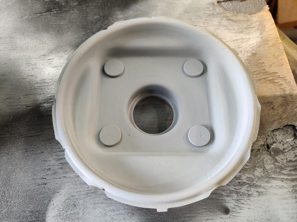
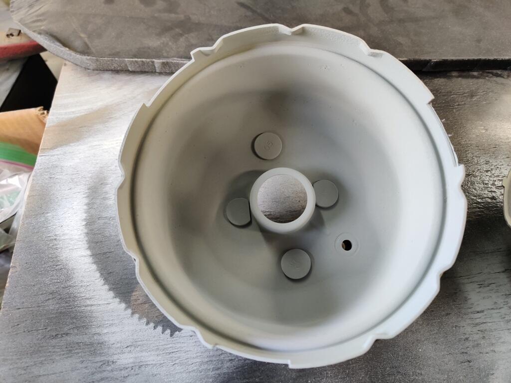
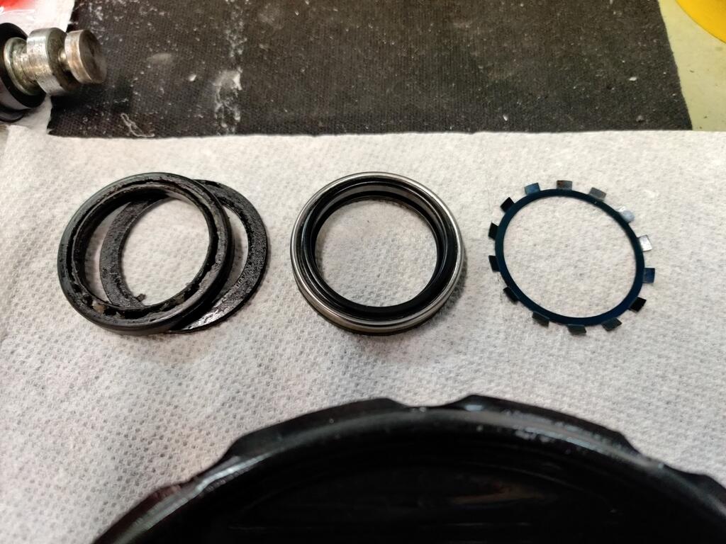
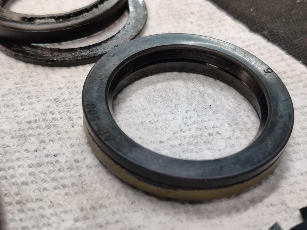
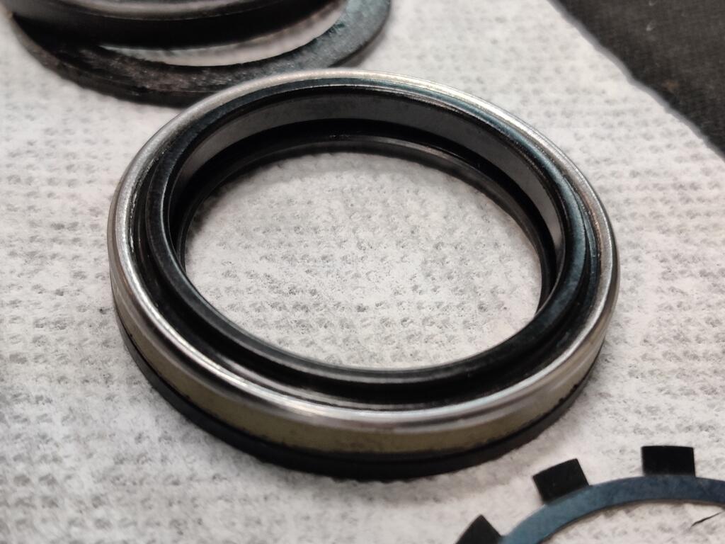
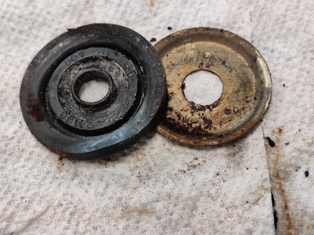
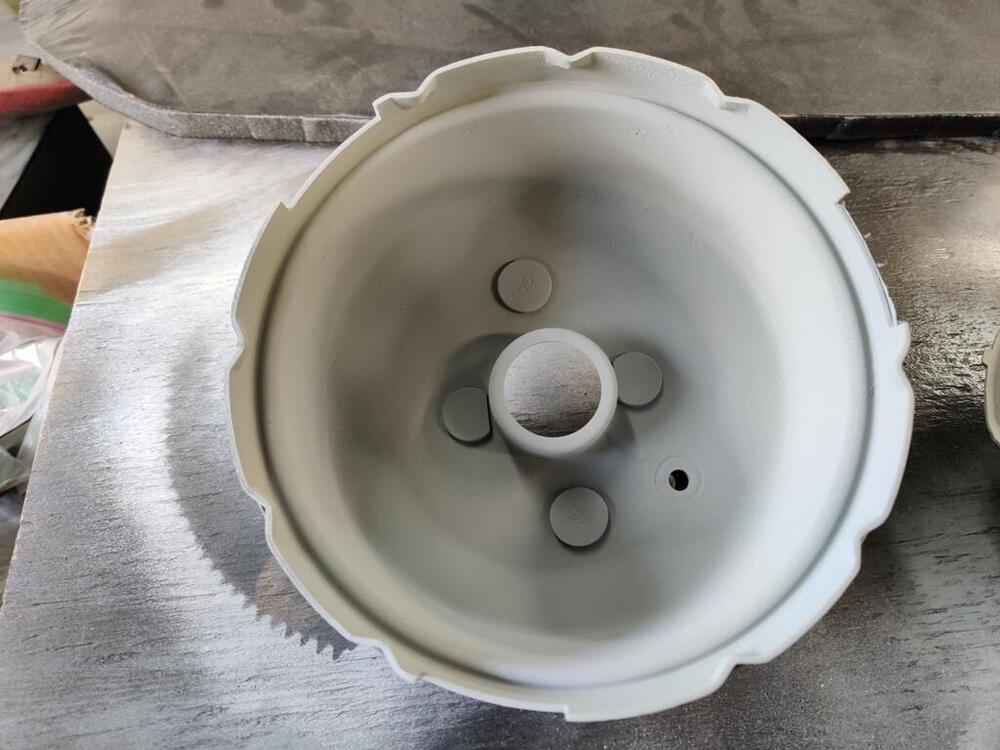
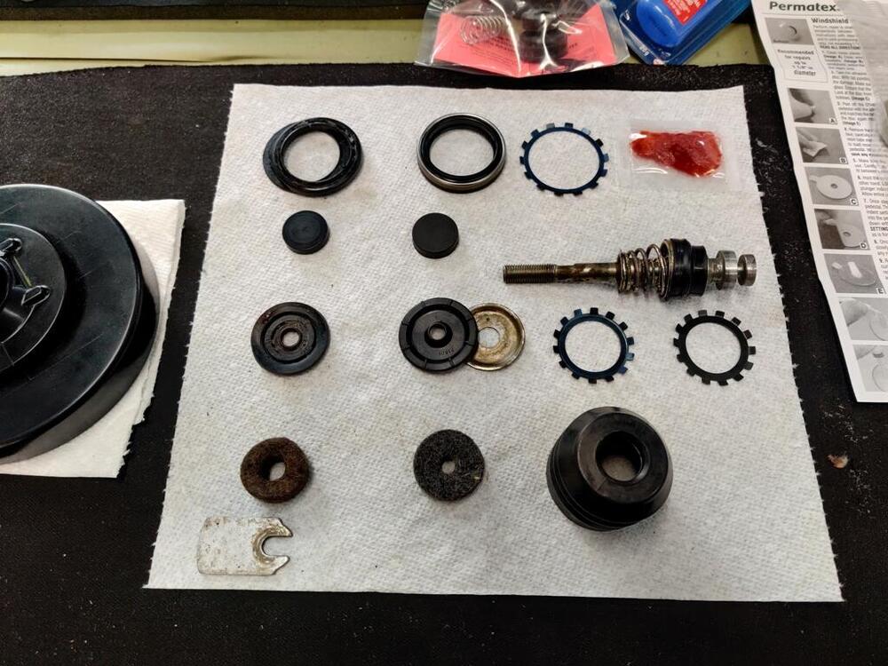
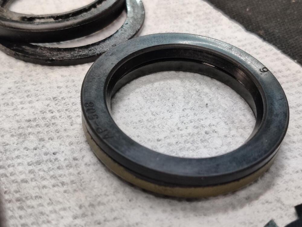
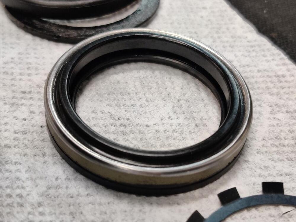
I glass beaded and primed (and painted) the inside of the cover and the back plate. Old parts aligned next to new parts, generally... I am not positive which way this replacement seal installs. It is different in design than the original one. It has a metal casing, whereas the old one did not. I think the new one installs with the black rubber backing (middle pic here) up facing upwards and with the spring retainer against it. The new one appears to be a press fit into the back plate. I will measure OD and see what the interference fit is.


-
So, you used both the black and the clear on the front side? And did you use the Alumiblast for the silver on the inside?
-
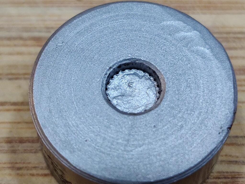
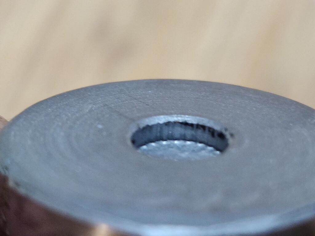
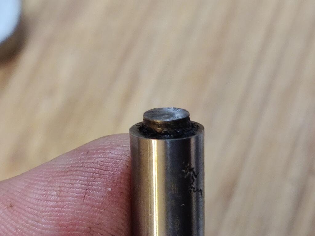
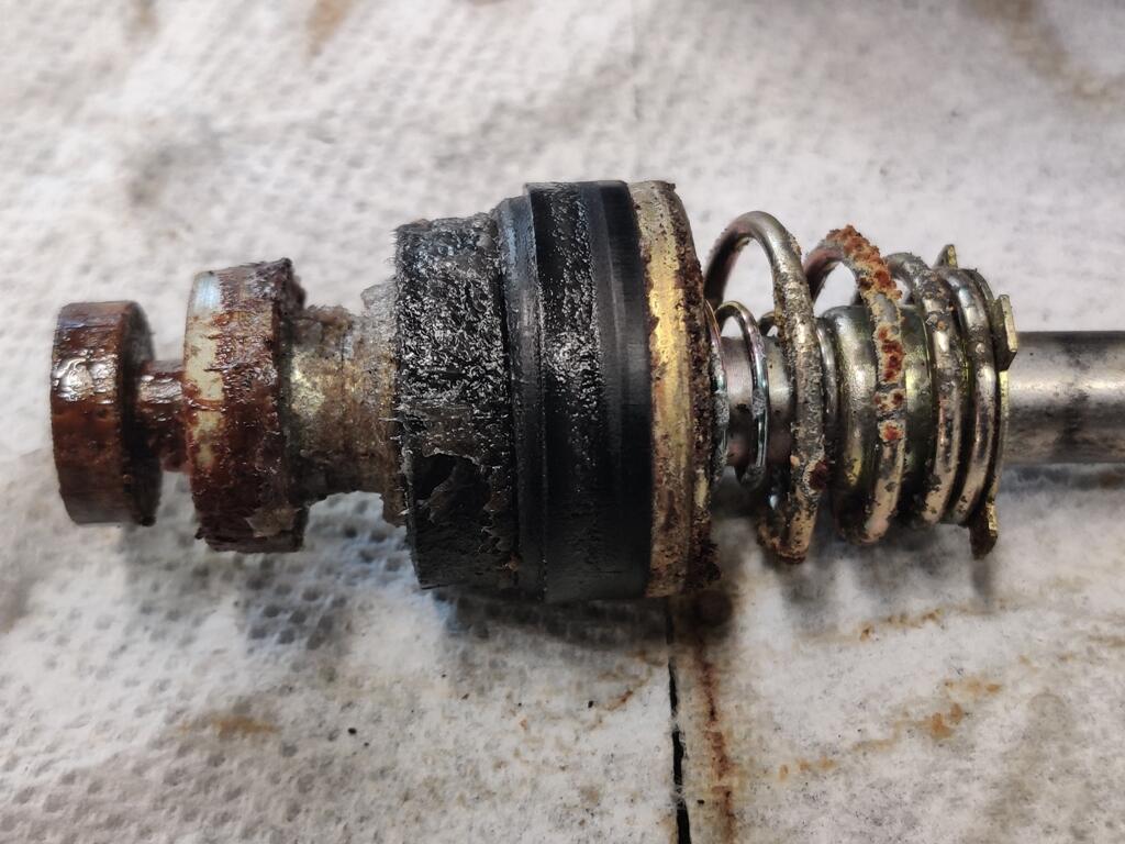
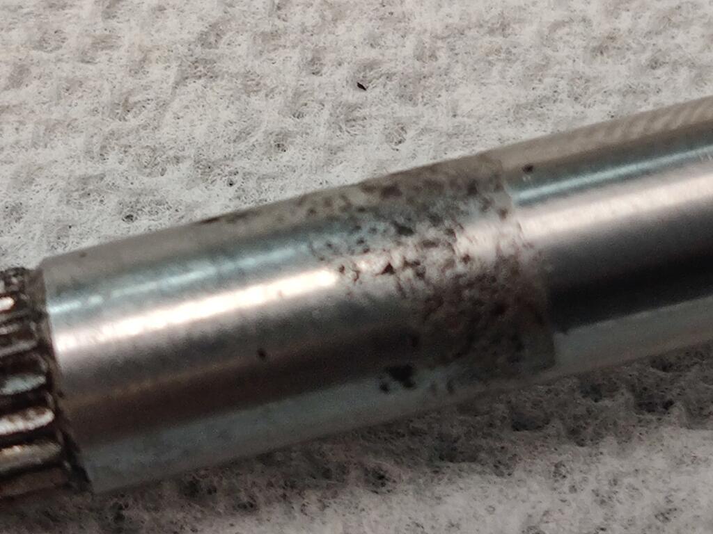
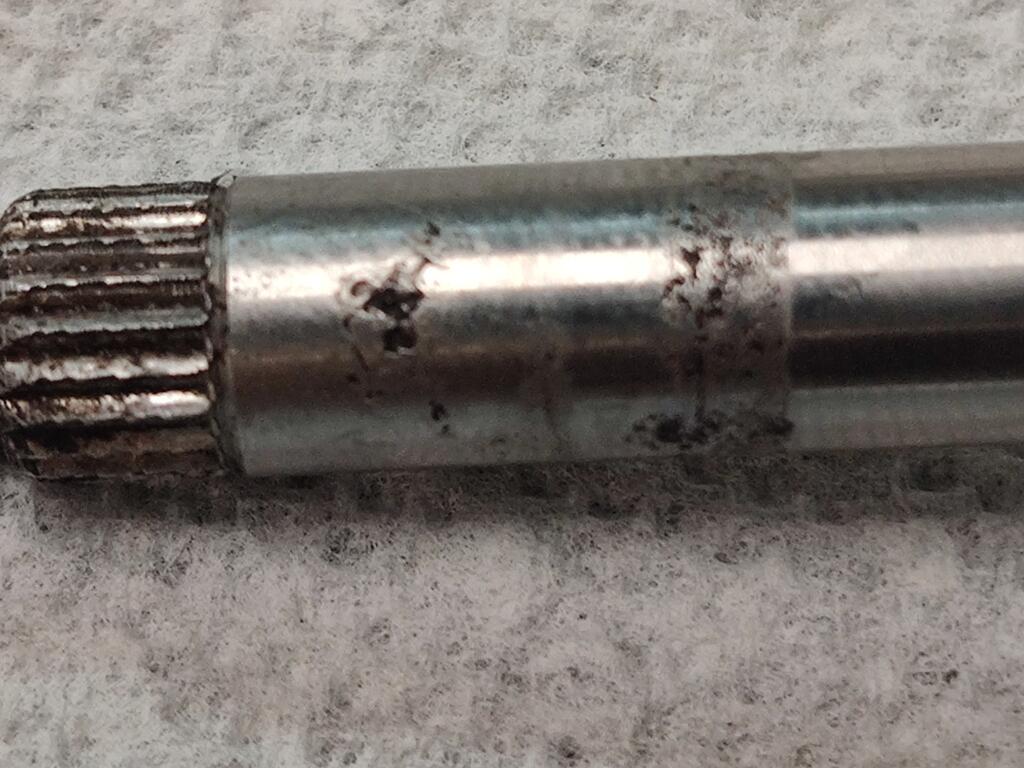
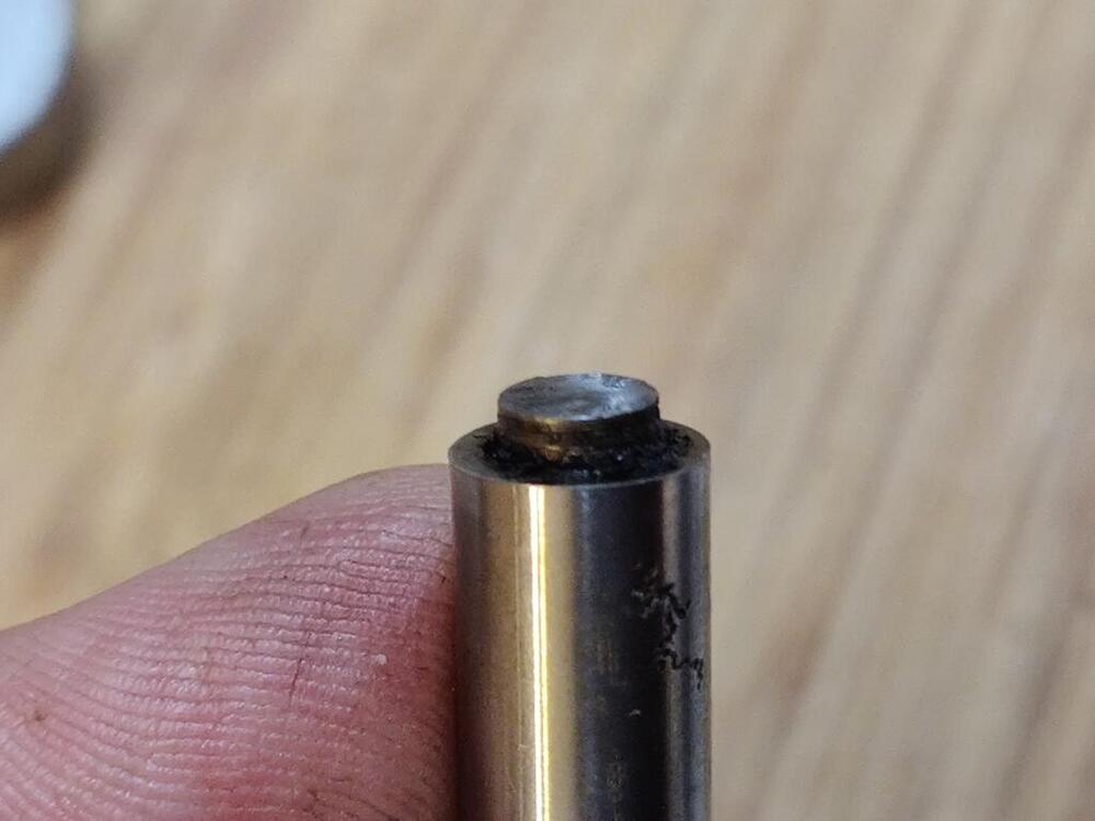
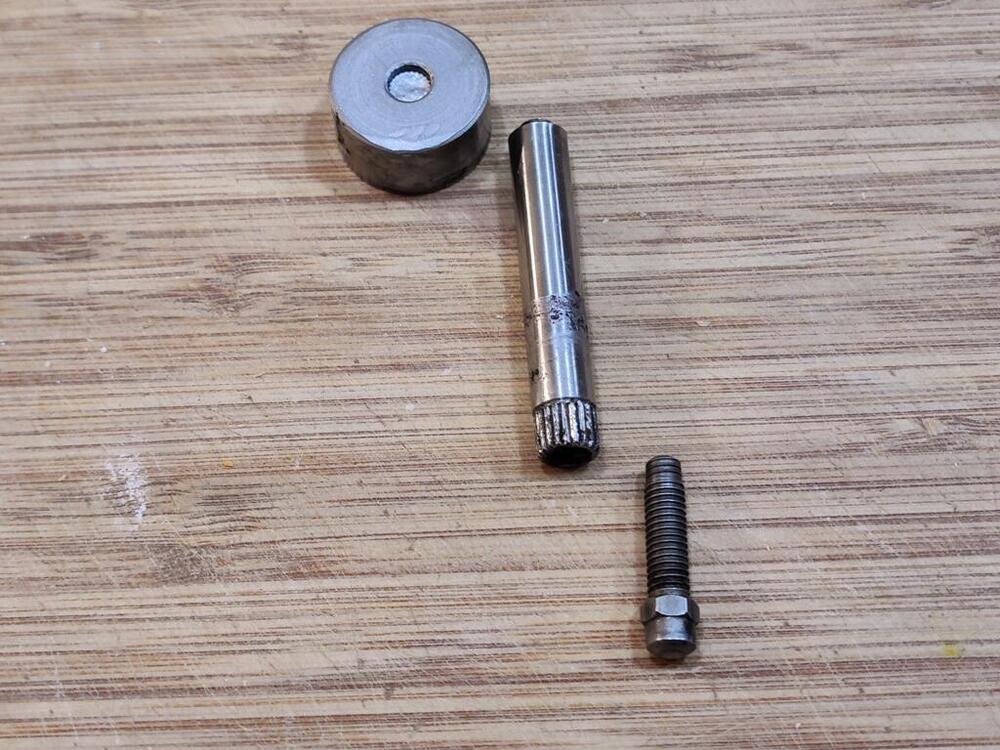
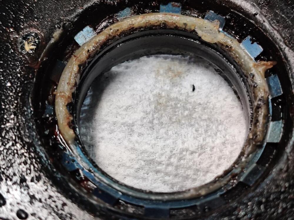
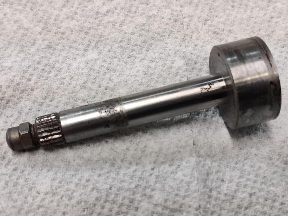
Well... I did some deconstruction on it just now. I couldn't get the big end off. Couldn't figure out how it was on. I could see lathe turning marking on both sides of the big round and the shaft was highly polished. So, I figured it was a press fit. I heated the big end and some fluid boiled out of the joint. With some confidence, I clamped the shaft in the vise and started hammering on the big round end. Even with lots of heat and lots of force, it barely moved. So, I thought, "gosh - could it be threaded on? And I took some large vise grips and clamped on the big end and wrenched it. It broke of course. So, the shaft is splined and pressed into the big end. And, it is splined on the other end as well. I was able to get the tip unthreaded without mangling it. Now... I need to have one made.


-
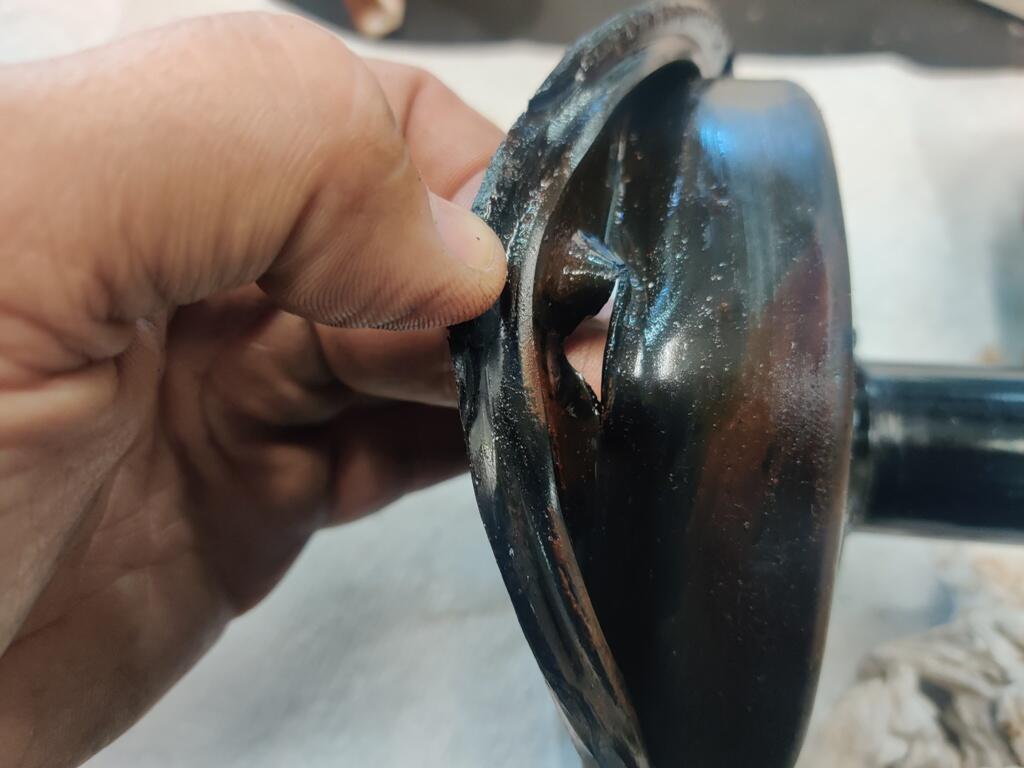
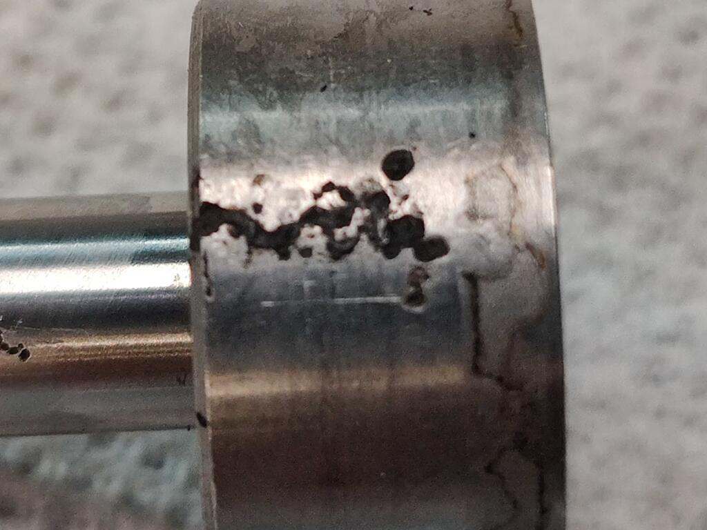
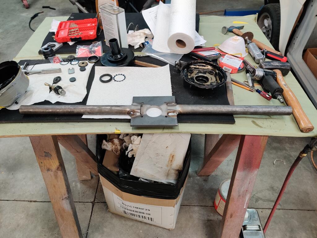
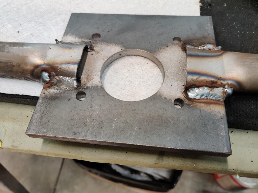
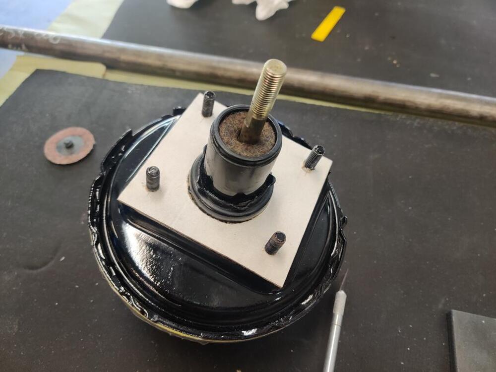
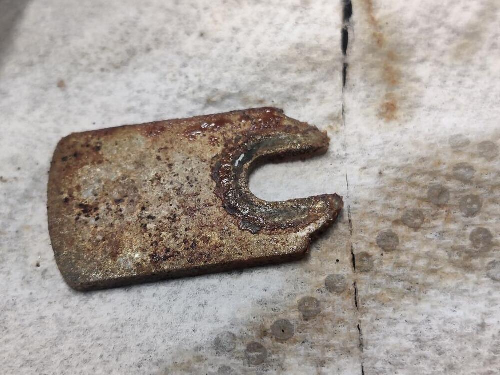
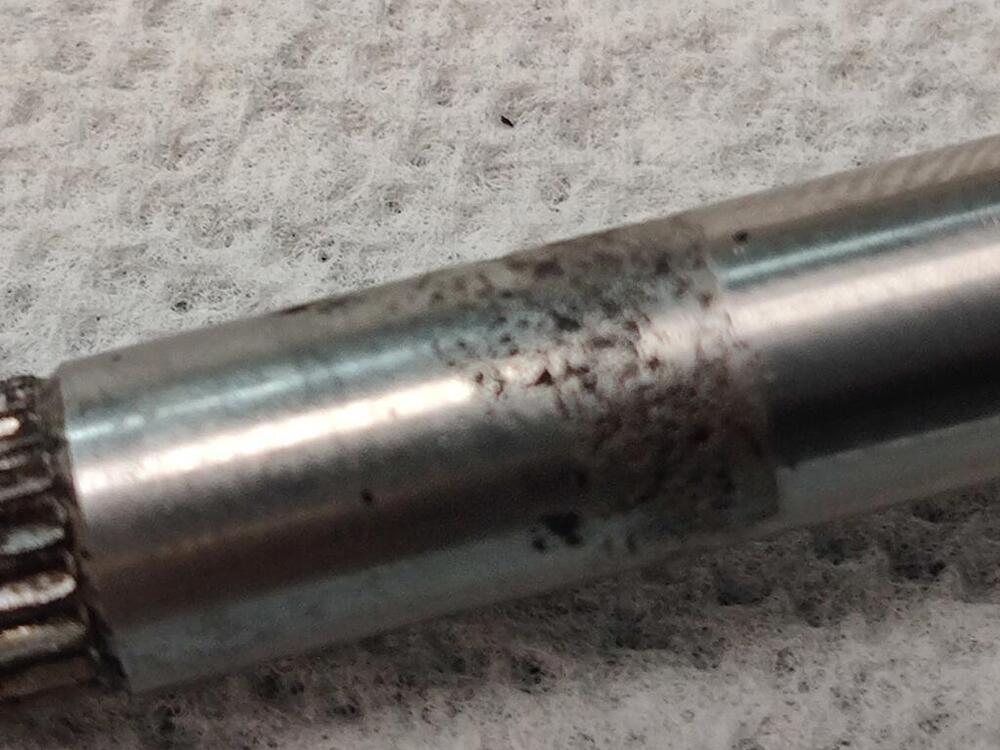
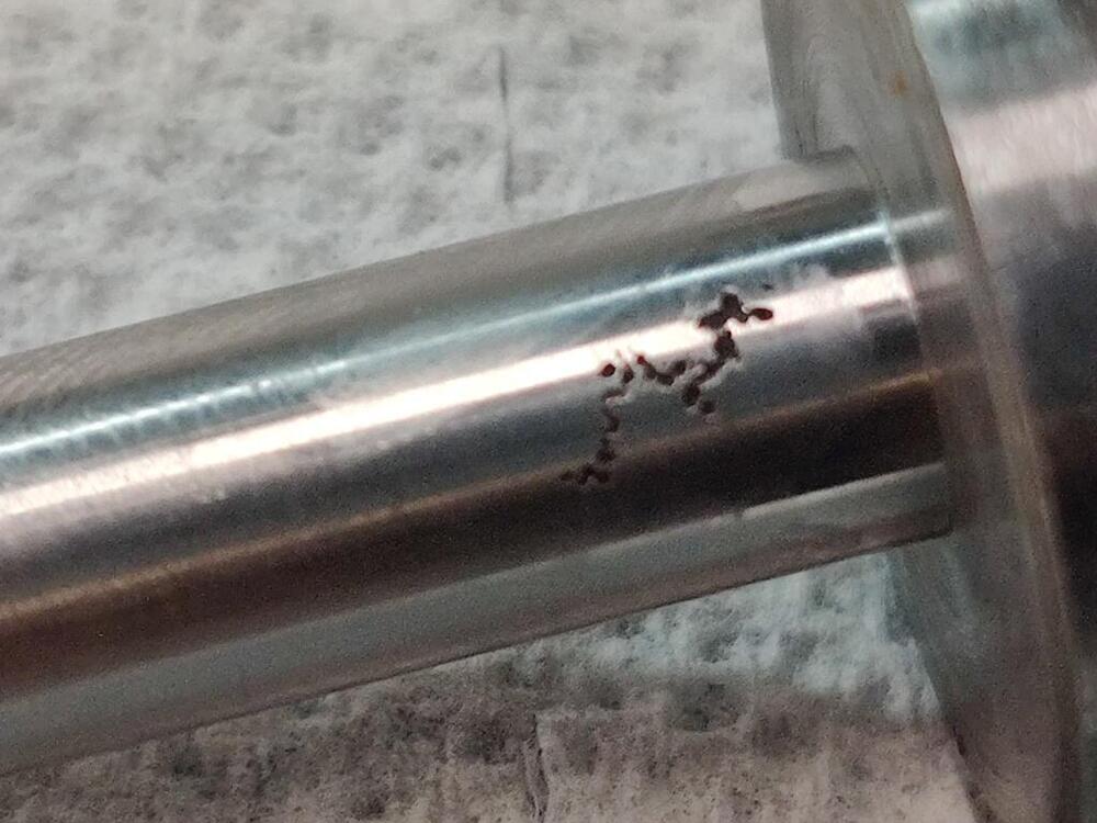
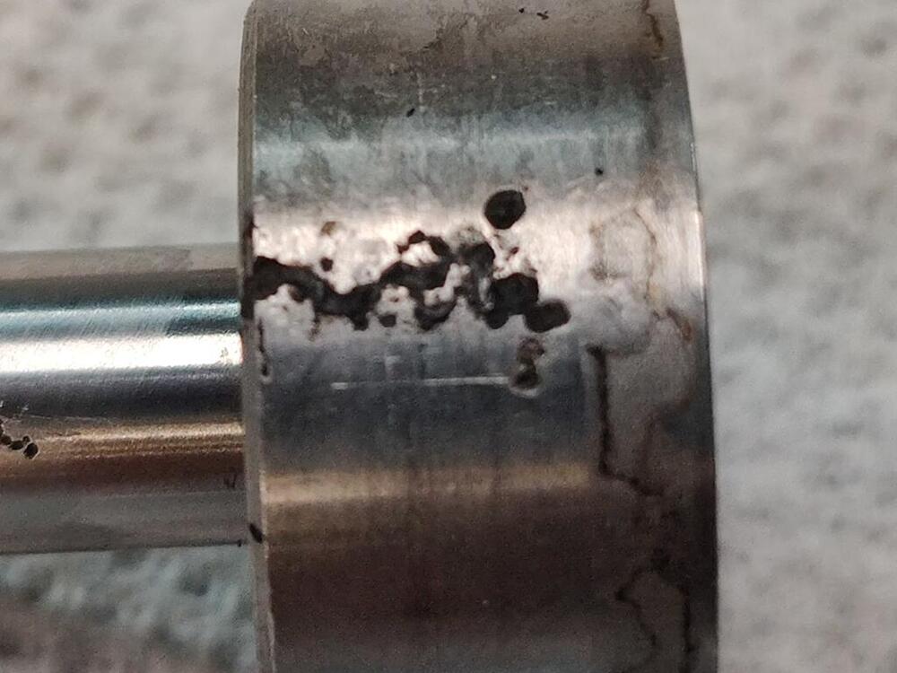
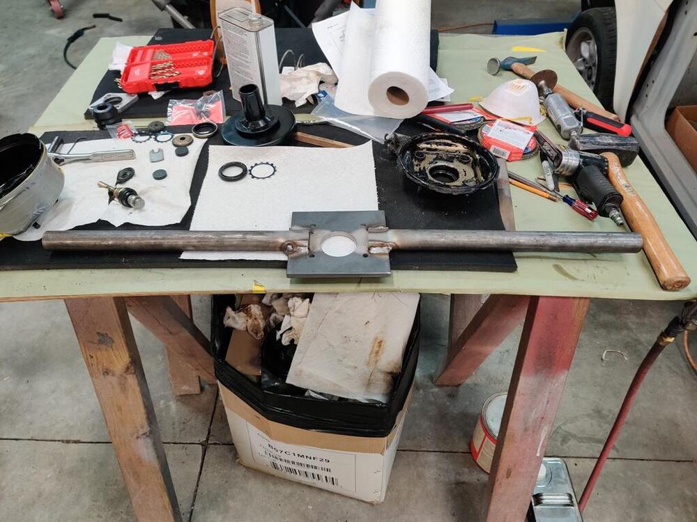
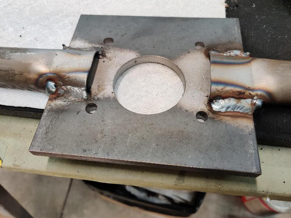
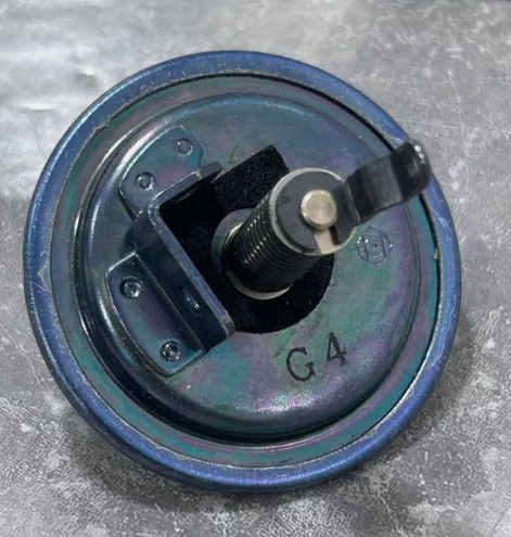
Making the tool went well today. It took me a few hours. The plate I found in the "drops" area of my close-by metals store was quite thick, so it took a while to drill through it with drill bits and a hole saw. My re-sharpened titanium coated drill bit wasn't working well. Instead, I made a trip to Home Depot and picked up a new set - this time "cobalt" drill bits. The set has two each of many of the common sizes, which I like. I made the tool a bit differently than the factory one. The handle portion overlaps the plate only on the top side. The bottom side of the plate is totally flat. I squeezed the handles in my hydraulic press to squash the ends that are welded to the plate. On the underside of the handles, I cut a way a the part that would overlap like the top does and just butt welded to the side of the plate. Inspection when I got it apart revealed a large tear in the diaphragm. I was pleased that the stop key came out easily. And I was surprised to see a large amount of grease on most parts. This part doesn't look good however: This part looks to be chrome plated. And rust got to it and caused some bad pitting. I don't see this part in the parts catalog, not that it would be available anymore. But, I don't want to put this one back in. Perhaps I will have to get one made. The booster had some old brake fluid sloshing around inside. So, I plan to refinish the inside of the cover and probably both sides of the back plate. So far, so good.


-
Very nice job on the speedo cable!
-
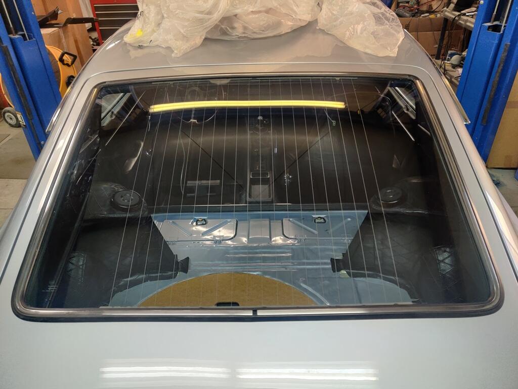
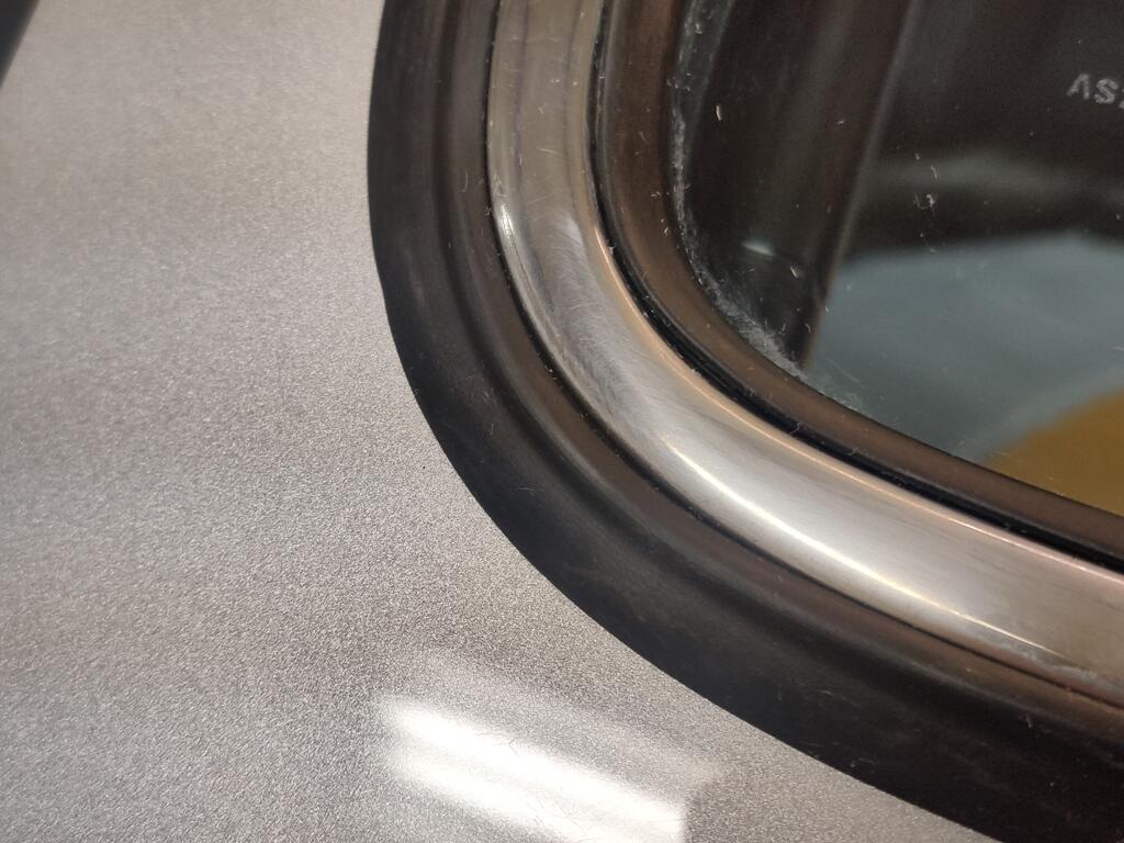
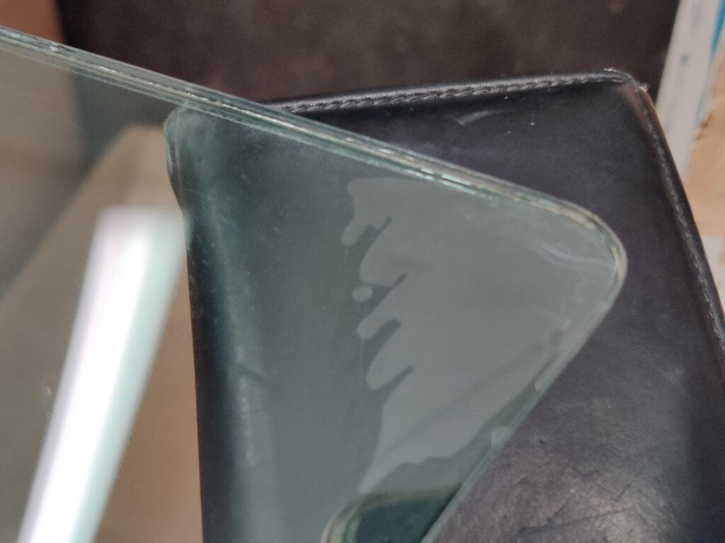
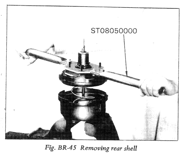
With the assistance of a helper, I was able to install the hatch glass again last night, this time with the stainless trim already installed in the gasket. The hardest part was getting the outer edge of the seal to seat against the outside of the hatch surface, when pulling the cord to start bringing the seal lip over and to the inside surface of the pinch weld flange. I started pulling the cord in the middle of the bottom side. With the stainless trim installed, the outside edge of the seal wants to tuck down inside the hatch glass opening instead of being pushed outward to lay flat on the outer surface. To solve, you need to push/pull the hatch glass/weather strip assembly downward toward and against the bottom of the opening. If you do not, the glass will want to move away from the bottom side and as you pull the rope, the outside edge of the weather strip will tuck inside outer edge of the opening (the part where the outside surface of the hatch turns 90 degree downwards to create the flange for the hatch glass. After a couple of false starts, where I had to put the glass back on a work surface and put the rope back into the groove, we understood that we needed to keep the glass tightly against the bottom edge as I pulled the rope to bring the inner lip of the seal into the inside of the weld flange. Pulling the rope around to each side and up each side equally, and then across the top, there were no issues. We found that for the top edge, pushing on the outside of the glass (to press it into the window opening) worked better as I pulled the rope for that side (fourth, and last, in the order that I went in). This time, there are no cuts or nicks in the rubber seal at all. For some reason, this factory seal had a bunch of gummy stuff all over it, perhaps to assist with installation, if I am guessing. It seemed a lot more flexible that the other one that I destroyed. Perhaps it was much newer than the previous one I used. I still need to remove that with adhesive remover, and when I do so, the stainless trim won't look dull like it does now. Today, I plan to work on making a copy of brake booster tool ST08050000 so I can get my brake booster apart to start rebuilding it.


-
I just set the ignition timing on my car yesterday using the process I described above. I could warm the engine up, check the timing with a light with the ported hose connected to my vacuum advance, and see if the setting is different than what I set it to yesterday with the hose disconnected... There is vacuum present at the rubber hose (to vac adv. assembly) - I verified that yesterday. It is slight. Perhaps it is too little to cause movement at the plates in the distributor at the present idle speed. Easy enough to test.
-
Me either. I am not certain that either the correct vacuum advance, or the NOS (and incorrect) one does nothing at idle. The proper way to set initial ignition timing is to disconnect the vacuum advance, yes? Separately, I have always wondered why the timing specs are at RPMs that are "too low". For my Euro distributor, the spec is 17 degrees BTDC at 550 RPM. To achieve that low idle speed, I have to unplug the vacuum advance unit and seal the tube to the intake manifold, mess with the throttle plate screws on the SU's to lower idle speed, but keep the front and rear carbs in sync. Then set timing at 17. And finally, bump the idle speed up to something a bit more pleasant (750 rpm). And reattach the hose to the vacuum advance. By the way, disconnecting the NOS one solved the rev/die situation. And with the correct vac advance and linkage bits, the engine is not doing that. I suspect that the Pertronix unit didn't like the amount of movement the NOS vac advance was causing. I will be checking (as best I can) the timing advance as the engine revs soon.
-
Found these in my misc. zip lock bags of Datsun hardware - so I am all set for the hardware now for the quarter window interior trim panels. I installed the rear hatch glass into another NOS rear hatch weather strip I had on the shelf. And, I again polished the stainless trim for the rear hatch glass, only this time, I installed it while the hatch glass is off of the car. I don't have any more of these weather strips on "the shelf"... so this one needs to go in without any problems!

-
I reinstalled the original vacuum advance that came with the Euro distributor when I bought it about 30 years ago. It still holds vacuum when applied with a tool. So, I primed and painted it (silver). I'd still like to find the correct replacement (yellow chromate/zinc). With it installed, the engine does not rev and die like it did with the other one (NOS but of unknown application). The shaft that the spring goes on is both longer overall, and longer when it is fully pulled in by the vac adv diaphragm. So, there is that known difference. I guess I will keep looking a replacement original part "22301-E4601". But, it would be nice to have more knowledge about these original vacuum advances, so I might have a better chance at finding one that would be a suitable replacement (with swapping the linkage parts).
-
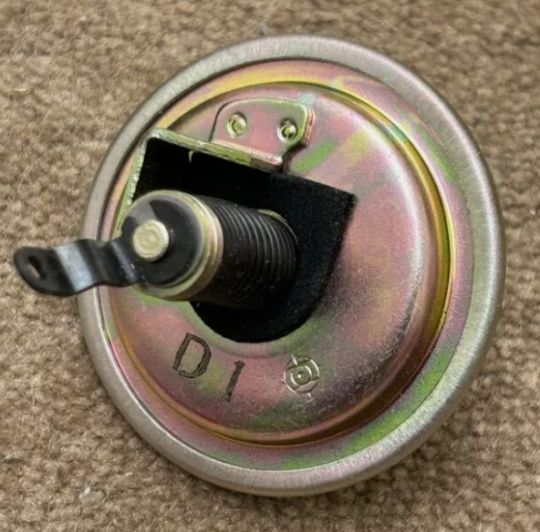
Does anyone know what these letters and numbers ink stamped onto the vacuum advance mean? I see a lot of different combinations on the parts I have seen for sale. A lot of times, there is not vehicle specific applications listed. Are these just date codes? I'd like to replace the original vacuum advance on my Euro 240z distributor, but I won't have much luck looking for that part by application. I bought a new vacuum advance that "looks correct"; however, when I hook up the vacuum line to it with the engine operating, the engines revs and dies repeatedly. I am running a Pertronix ignition pickup, which may matter. And I plan to do some testing on the new vacuum advance as well as my old one which is still functional. But, it would be nice if I at least knew what I was looking for in a replacement vacuum advance.
-
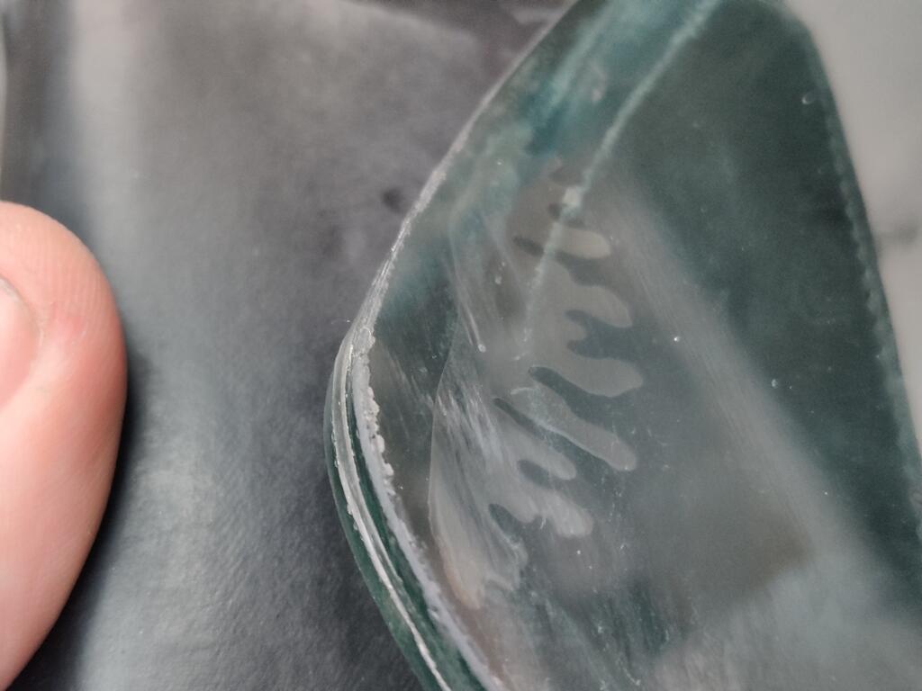
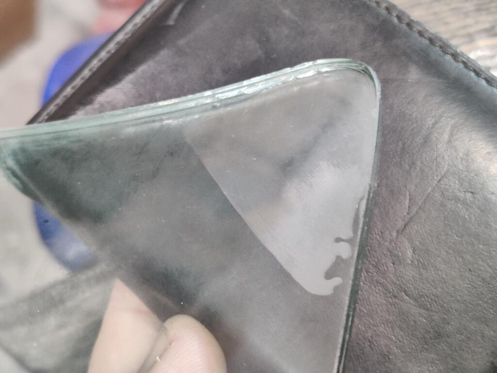
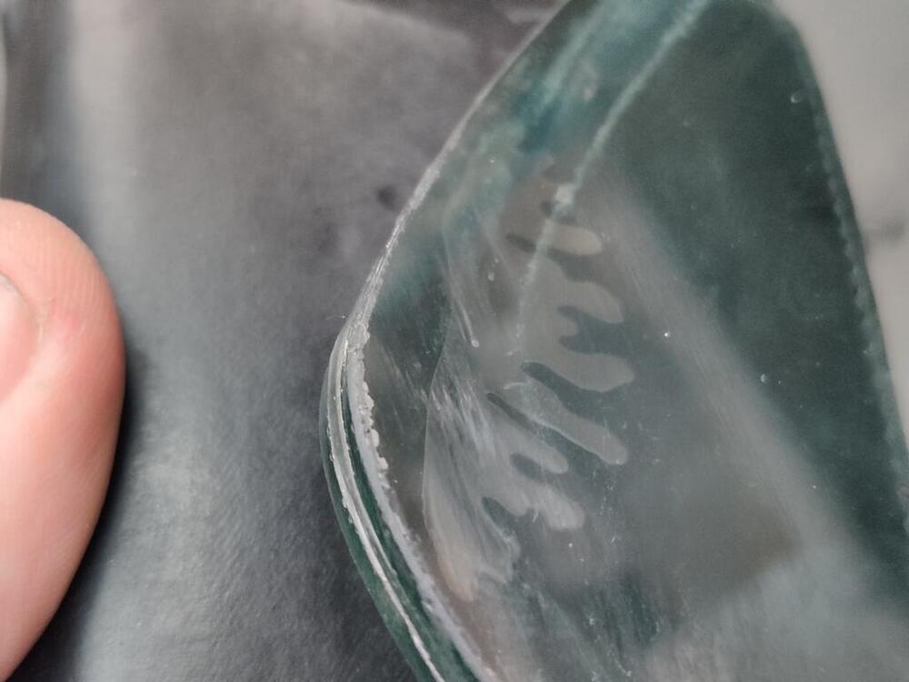
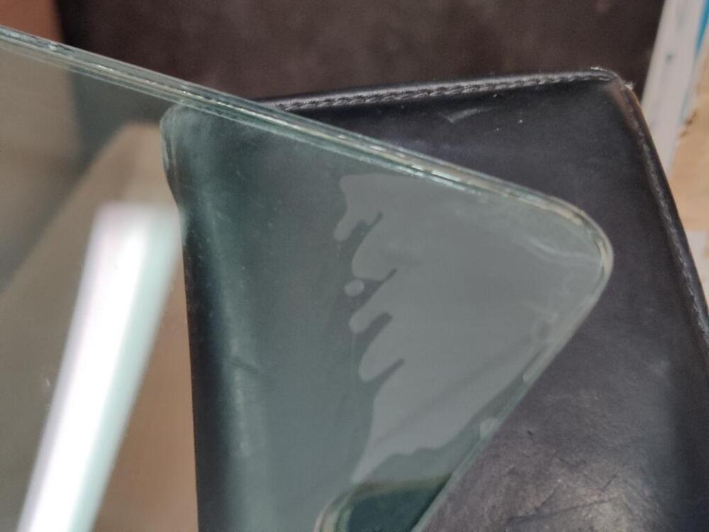
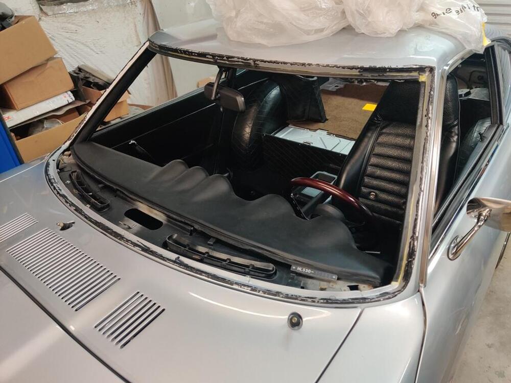
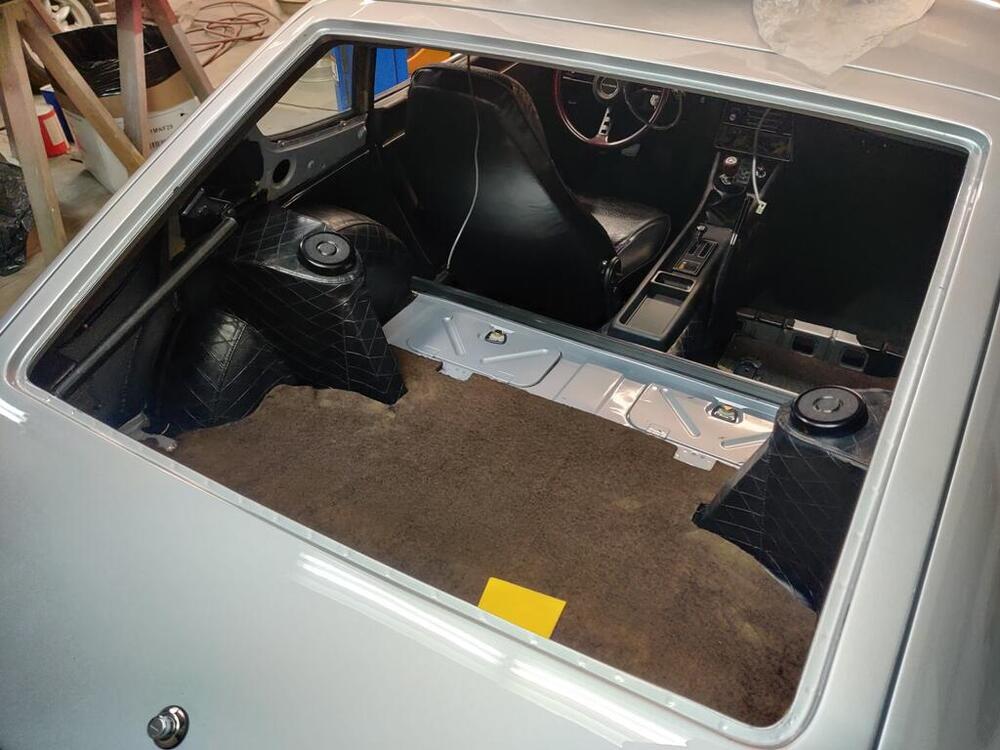
Thanks to all who responded! In other news, a friend from VA visited this past weekend, and we tried tackling one of the tough jobs: installing the new stainless trim in the windshield gasket. I bought a tool from Lisle to assist and some Precision lube. We gave it a go... and even with two "car guys" being extremely careful, we sliced the gasket in many places (and I sliced myself in three places) trying to install it. I am concluding that it is impossible to install the stainless trim after installing the windshield in the car without cutting the gasket to shreds. It may be possible with an aftermarket windshield gasket, but it is certainly not with an old NOS one. So, while he was here, we then cut up the NOS gaskets for the windshield and the hatch to get the glass out. The urethane adhesive I used didn't do an especially good job of gluing the gaskets to the body - this I am thankful for. It did, however, do an especially good job of sticking to the body. So, it is a bitch to get off the car. One positive thing I guess: after install the windshield weeks ago, I noticed that in 3 of the 4 corners of the windshield, the two pieces of glass (front and back) started delaminating. With the windshield out, I may be able to repair that. Or, I may just try to source another windshield. Just to round this out, I recommend that you never install the glass without putting the stainless trim in the grooves of the gasket first. Out of all the work I have done on the car, installing the stainless trim on already installed gaskets is easily the hardest and most frustrating thing I have attempted. Removing the urethane adhesive from the body of the car is up there as well. I started removing the adhesive the rear hatch panel, and than part of the windshield. But I have a blister forming on my thumb, so I will take a break from that. I have gone backwards more than forwards this time.

-
The J hook on the early cars goes on the seat. The J hook on my 1971 car goes at the bottom front corner of the quarter window trim panel. Thanks for this pic! You can see that part much more clearly.
-
Anyone have any details about the hardware used here? This is a 1971 240z.

-
Referencing this nice exploded view and my comments earlier, #9 is the valve that got stuck. #10 is a rubber part that fits on #9. When the rod portion of #9 seizes in #12, then the cylinder operation stops working properly. I don't know exactly how it works, but I think #9 works like a one way valve - it seems to close the circuit, which then allows the main piston and primary cup to move fluid. When #9 is stuck in the "open" position, fluid just flows back and forth, and no force or movement of fluid is generated.
-
I recently couldn't get my clutch to bleed (just after I couldn't get my brakes to bleed), and the problem was the little slider valve found on the piston assembly. No pictures, but the little valve for the clutch master cylinder is much easier to get to than the one on the brake master cylinder. it has a little spring on it. Should be easier to disassemble and make sure it is not sticking.
-
With the "wet set" method, I was setting them in the installed state, adding gas through the inlet to the float chamber. I was setting the height of the fuel (as seen by looking at the translucent nylon tub attached to the float chamber outlet) to 20 mm below the casting separation line of the chamber and the lid. I switched to setting at 14 to 15 mm between the bottom surface of the float chamber lid to to the top of the metal portion of the float. I did this by cutting and grinding 2 3d size trim nails - one to 14 mm in length and one to 15 mm in length. Using needle nose pliers, I hold each and place them vertically aligned between the float and the roof of the chamber lid. I hold the float pressed against the nail, pinching the nail (vertically aligned) against the roof... and I blow into the fuel inlet. Using the 15 mm nail segment, air can flow from the inlet past the needle valve. Using the 14 mm nail segment, it cannot. I used this method with the rear carb only. I did this yesterday. Today I started the car and the fuel did not gush out of the vent in the chamber lid. I did not run it long or do a test drive. FWIW, this second method is what I always used for my other Z when it had SU's on it. I never had problems with either fuel overflowing or performance, for that matter.
-
So a quest for the highest acceptable fuel level in the chambers may not have any value at all! Perhaps I can investigate that a bit with the wide band in coming months.