inline6
 Subscriber
-
Joined
-
Last visited
Everything posted by inline6
-
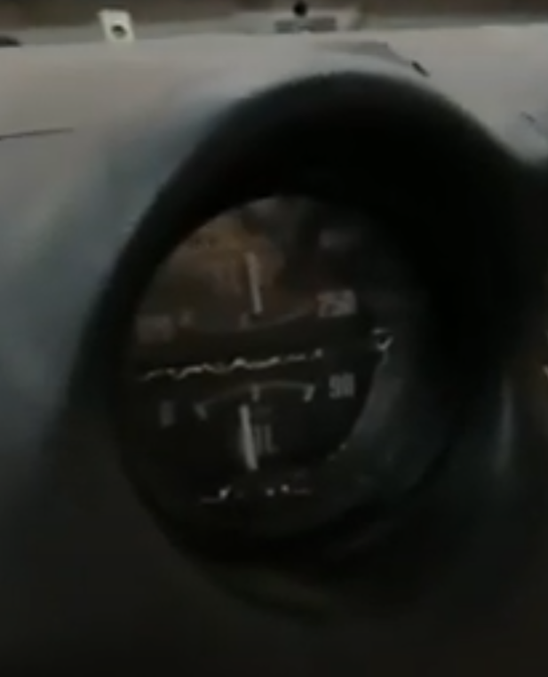
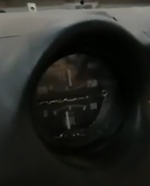
 Snagged this from a driving video I shot a couple of days ago. I have just stopped from pulling into my driveway. Temp gauge reading is actually even higher than I was saying - looks like the needle is cutting through the P in TEMP. Thanks @Captain Obvious for the pictures and comments about adjusting. It is a bit of a pain to get the gauge out at this point, but it is on my short list.
-
Nope. I can't figure out what the issue is. Bad batch of OEM filters which are too thick? Something wrong with my air cleaner housing? I don't know.
-
Regarding the fuse cover, mine was slightly melted. I found one on Ebay a while back that was decent. Do not use any kind of thinner on them to clean them up. The white lettering on them is painted on and will rub away easily. I am pretty sure that the place in Marietta is the same company. When I contacted them, they responded from CA. They said that during Co-vid, the had to shut down the GA location, but that they were the same people. It was expensive.
-
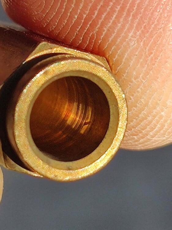
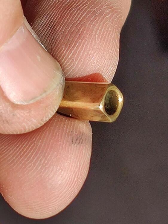
The replacement connecting rod for the carburetor showed up in the mail today from ZTherapy. Thanks @Patcon for suggesting I contact them. Unfortunately, the replacement needles and seats did not show up in the mail today. So, I found myself removing the rear carburetor needle and seat... just to have little look see at it for issues. Well, one thing led to another, and I found myself on Youtube watching a video someone made about their needle and seat not working properly and causing fuel to gush everywhere. That person used a Q tip in a drill and some metal polish to polish the inside barrel of the seat. I decided to have a close look at mine. I wasn't able to take a good picture, but you can kind of see from the above one that the inside of the seat bore where the needle sits is not exactly smooth. So, I grabbed a small section of 1500 grit sandpaper and rolled it around a drill bit which I inserted into this bore. Using the drill, I smoothed out the ridges on the inside of the seat. Then I used a Q tip and some metal polish and a drill to polish the inside of the barrel. I then sanded the corners of the needle with some 2500 grit sand paper and polished the corners of it as well with the Q tip and metal polish: I After cleaning them, I put the needle and seat back together in the carburetor. Because I had to take the linkage apart to install the new connector rod, I synchronized the carburetors again. Here is something interesting: While I did the standard balancing procedure which included setting each carburetor's set screw so that each carburetor had the same flow at idle, and then screwing in the auxiliary shaft screw (to activate the linkage against both carburetors) and setting the balance screw to have the same flow during throttle application, I also did something similar for the choke. This is not something I saw in the factory workshop manual. For proper choke function, the factory workshop manual provides instruction to set a specified gap between the throttle plate and the body of the carburetor when the choke lever is pulled. This is to be done for each carburetor. After this is done, in theory, when you pull the choke lever, the choke mechanism will open the throttle plates on the front and the rear carburetor the same amount. I did as instructed in the factory workshop manual. However, I then started the car with the choke lever slightly activated. This raised the speed of the engine above normal idle speed. And then, I checked the flow of air through each carburetor using the Uni-Syn. Well, the flow was not the same. Similar to the procedure to balance the front and rear carbs when the linkage is activated, I used the Uni-syn flow meter to set the flow between the two carburetors to the same amount with the choke lever in operation (slightly). To adjust flow I had to shorten/lengthen the connecting rod for the choke. After completing this adjustment, when I pull my choke cables to start the carburetors, both throttle plates are opened to a position where both carburetors are flowing the same! I never was able to get the chokes working well on my track Z (when it had SU's), but I think this will be the ticket to getting the chokes to operate well on this car. I will be able to test that tomorrow when the engine is cold. I did take the the car for brief drive after messing with the needle and seat. So far, so good! I hope I have solved the issue with the rear carburetor puking fuel.

-
This is the place: Decorative Metal Coatings 2613 Temple Heights Dr. Ste. C Oceanside, CA 92056 Tel: (760) 746-3378 Fax: (760) 940-8781 Email: Accounting@DecoMetalFinishing.com Those plates are part of the ash tray parts. The plates seems to be something you can grab onto to lift the front of the ash tray out of the console. I had two sets of ash tray parts done.

-
I found information pertaining to this issue on this site and on Zhome.com. However, rather than bringing back a thread last contributed to in 2013, I will start a new one and hope I can fix the problem I am having. The Needle on my temperature gauge is definitely going to high. I know however, the engine is not overheating because I have checked it with a laser temperature gun. Here is the info I have so far regarding the problem. When I first bought the car, I got the engine running for a brief amount of time before taking the engine out for rebuilding. I ran it up to temp in my garage (car was inoperative) and noted that the needle on the temp gauge was a bit high. Here is a slightly blurry screenshot from a video I took at the time. The engine was fully warmed up: Fast forward about six and half years and with the car fully restored, the same temperature sender put the needle (same gauge) on the base of the last stroke of the "M" of TEMP. That is not all that far away from the red zone of the gauge - near the "250". So, I figured to fix this, I would just need to buy a new temperature sender. When I changed to the new one, an aftermarket unit, I saw essentially the same thing, but the needle goes to the left side of the "P". I read in one forum thread that buying an OEM temperature sender fixed the issue. That seemed pretty promising. So, I sourced an original "Sankei" sender from a seller on Ebay. I switched to that one... and again found the needle goes to the left side of the "P". As I have continued to look for information about solving this problem, I have come across this article on Zhome.com which was referenced in an old thread on this site: In the Zhome.com article, there is mention of "adjusting the voltage regulator". From the context in the write up, it seems this is a different voltage regulator than the one for the alternator. Instead, this seems to be something, perhaps inside the gauge itself. However, the author is working with a 280ZX, so I am uncertain of the applicability of the information to my 1971 gauge. I did consult with @SteveJ back in November about using a "pot" like this person described in their post in the first of the mentioned threads above. I purchased this one per his recommendation: https://www.mouser.com/ProductDetail/BI-Technologies-TT-Electronics/93PR50LF?qs=UjOdgN%2FjCTVtZlza%2Bf%2Fo7g%3D%3D So, that is what I have so far. My plan is to check the three temperature senders that I have for differences if any, compare them to the specs provided in the Zhome article, to learn anything relevant about the voltage regulator and try to adjust it if possible, or to wire in the "pot" to ultimately resolve this issue if that is what it comes to.
-
Is that a BMW buckle receiver?
-
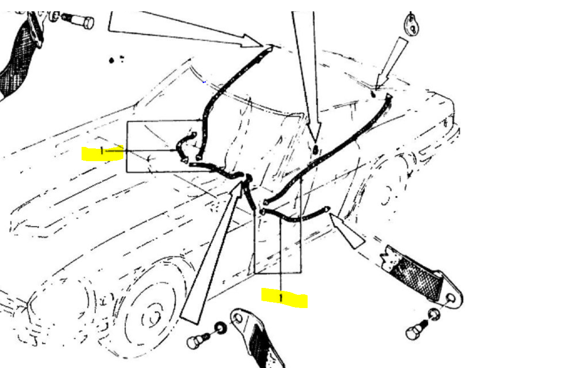
Even though the description says "holder", that appears to be for the belts. I don't see the part I am asking about in the car parts manual info.

-
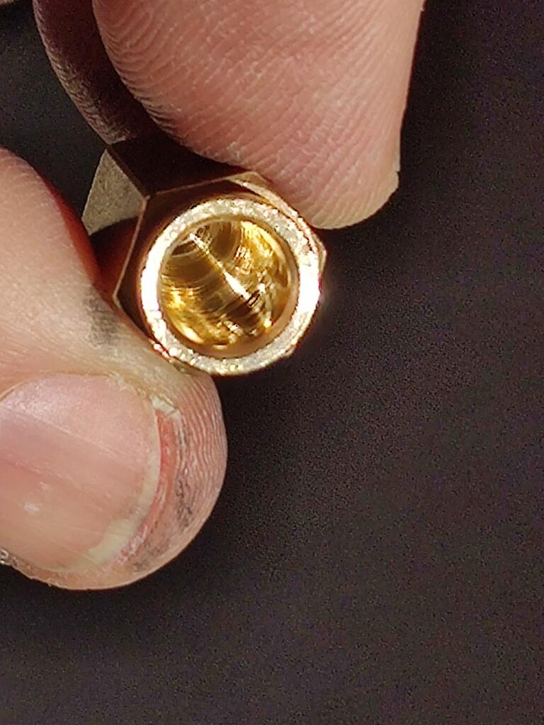
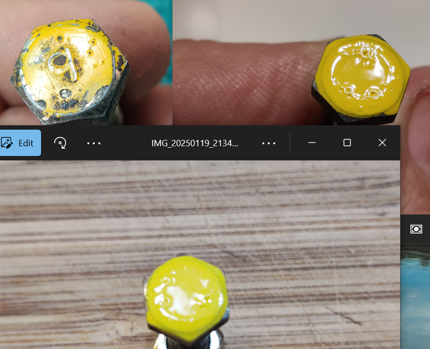
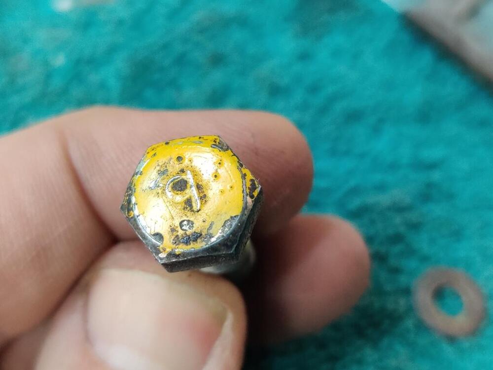
I bought some of this yellow paint to see if it might be close to the stuff that was used in the original assembly line. It was inexpensive, so I thought I would have a look. Lighting is a big factor in the look from a picture. But here is an original fastener with paint that is in pretty good condition, along with a fastener that I dipped into the new paint. My skin color is darker in the picture of the new paint, which tells me the lighting is darker. I also took a picture in another room (kitchen) with different lighting. It looks reasonably close in the pictures, but I think is a bit "lighter" than the original paint.

-
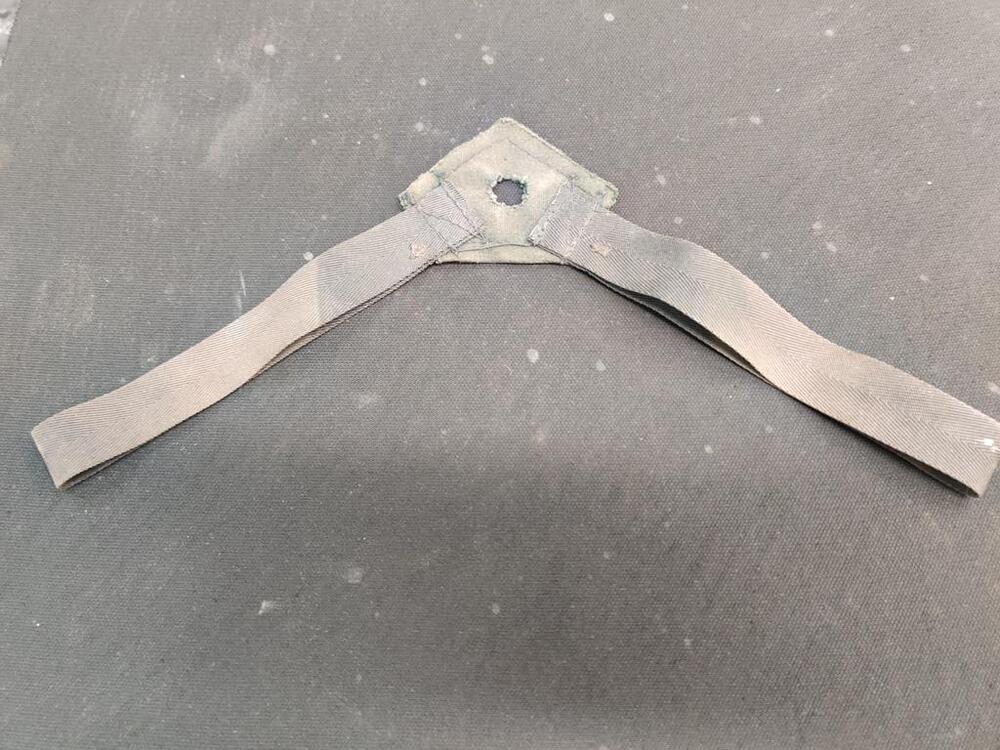
Is this original to early Z's - 1970-71, or only later years? To install it, you slip it under the center console, and run the forward most of the three back screws through the hole. The straps hang down on each side of the transmission tunnel. And you slip the inner most seat belts through the loops. In theory, it keeps the seat belt from falling down to the floor in between the seat and the tunnel.
-
Oh, while I was doing the test drive, the rear carburetor needle/seat/float failed again. This, after I was able to drive the car many times, and trouble free for about 100 miles. I was about a quarter mile from the house, and the engine started to fail to idle. I wasn't sure what the problem was, so I limped it home. When I opened the hood, I smelled gas, and saw that fuel was all over the place and dripping onto the header. Awesome. I decided to take a thin wire and reach down the float vent tube... to tap the float, which in theory, would unstick it. I tapped the float down and it bobbed back up again. I did this several times, and could hear the float contact the needle when it would bounce back up. Bounce, bounce, bounce, followed by tap, tap, tap. I turned the ignition key and several geysers of fuel came out the float vent. Awesome. I stopped there. I think I will replace the needle and seat next. There must be something wrong with it.
-
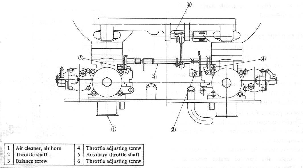
"sticky" throttle linkage has been a problem with two out of two 240z's I have owned. To go from no throttle to just a little it of throttle, there is noticeable resistance. I notice that as I try to apply a gentle amount of force, nothing moves. Then I apply more force and more force, until finally, the linkage "jumps" open and the car jumps forward. Driving the car to work the other morning for some show and tell, and getting into the midtown Atlanta area during the commute, this issue was extremely annoying. Yesterday, I worked on all parts of the linkage for the better part of 2 hours. Everything in the linkage has been examined and lubed. Adding grease to the auxiliary throttle shaft (5) helped a little. I disconnected all of the pieces in the linkage and checked each one for issues. Each piece in the system operates smoothly. With the gas pedal disconnected, and carburetor linkage return springs disconnected, I operated the connected parts of the linkage. So, the (5) aux shaft connected to the throttle shaft that slips into eyelet of the bracket on the fire wall, the rod that connects from that shaft to the bell crank, and the rod that goes from the bell crank to the gas pedal. The only thing I can detect as a potential problem in that assembly, as far as resistance to movement goes, is that the rod that goes through the rubber bellows may be rubbing against the inside of the bellows a bit. It is hard to tell with the other end of that rod disconnected from the gas pedal. But I felt some kind of rubbing or vibration coming through the bell crank when operating the linkage. I removed the gas pedal and its mounting bracket (which is made of plastic) and put grease on the pivot points. With that reassembled, I tested movement of the gas pedal alone, and it operated smoothly. However, when I reconnected the gas pedal to the rest of the linkage, and put the carburetor linkage return springs back in action, unbelievably, I got a squeak at the gas pedal pivot (which I confirmed was unrelated to the spring that is there. That is what I chased for a good part of the time I was working on this "little" issue. After I got that quieted down, I decided to do a brief test drive around the neighborhood to see how much better it was. I was able to control the throttle application a little better, but it's not good enough for me. Anyone else have luck addressing this? I have an old recollection from when I dealt with this issue on my other 240z many years ago. I believe I ended up changing the length of the adjustable connecting rod and that was helpful. In concept, that would alter some of the operating angles of the system.

-
@240dkw I sent an email to Ztherapy last night and they responded this morning. Hold off on looking for now - don't want to trouble you. They have one for a good price. Thank you for the response.
-
Awesome. The one for the front carb is bent different than for the rear carb. Let me know what you find whenever you get a chance.
-
Worth a shot. Email sent.
-
Well, I was. I have both nozzles moving up and down without sticking now, but I managed to break the bent connecting rod (4) on the front carb. Somehow, with the screw not holding the (1) Connecting Plate A to the nozzle, the spring loaded mechanism for the choke jammed fully upwards, and I couldn't for the life of me figure out why I couldn't get it to pull down where it belonged. In a moment of frustration, I pulled on the linkage to bring it back down where it belongs, and sheared the connecting rod at the bottom, where there is a 90 degree bend. Anyone have a "parts" front carb, who could bare to part with (pun intended) the (4) connecting rod?
-
I measured my nozzle drop and got .370" for the back carburetor and .365" for the front. So, it seems I did a bit of exaggeration there! I tweaked the #1 bar a bit on the back carburetor and was able to achieve smooth up and down movement of the nozzle. I tested its movement repeatedly. That one is good! I am in the middle of doing the same thing to the bar on the front carburetor to get the front nozzle to stop sticking. Evidently, these bars have to be in quite a particular shape, or they allow a sideways force on the nozzle that can cause it to stick when it is extended out of the nozzle sleeve.
-
Ah, yeah right. The nozzle and the connecting plate A are the only parts that drop... not the idling mixture nut. So the stopper is not in play. The nozzles are new genuine Nissan units. Everything was/is clean. They only stick when they are pulled down "a long distance" by the choke cables. It is this distance that they drop that I keep thinking about. I am fairly certain that they are dropping as much as an inch or more. I have found it to be excessive - it isn't necessary to pull the choke lever fully to enrichen the mixture for starting. When I pull the choke lever fully, then the nozzles drop much further. With the choke lever pulled fully, the nozzles are possibly more out of the nozzle sleeve than in at that point. That is when they bind against the nozzle sleeve. As soon as I touch the bottom of either nozzle, it snaps upwards (the linkage is spring loaded) returning to the normal position. I will try to measure the amount of movement of the nozzle when pulling the choke lever and report back.
-
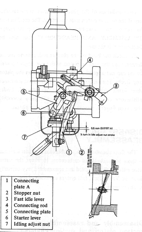
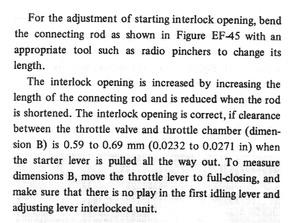
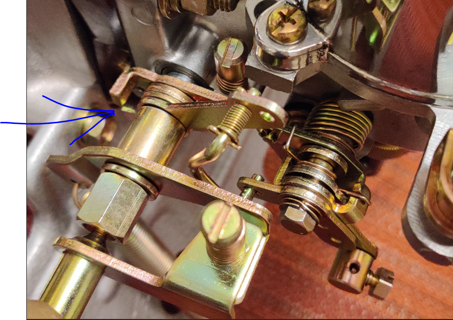
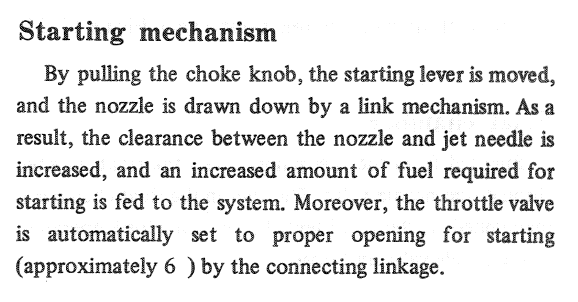
I've started driving the 240Z which I have been restoring since 2018. Many years ago, when I had SU's on my 12/70 240Z, the choke didn't work particularly well. I only needed to use the choke when it was actually cold out, like temperatures under 40, let's say. When I would operate the lever, the nozzles would drop. That would help the engine fire up, no problem. But, within a matter of a few seconds, the engine was "choking" on too rich a mixture, running really rough. I would, of course, push the choke cable towards the closed position. However, the engine would not run without me pressing the gas pedal - push the choke all the way in, it would die, leave it partially out, it would run very rough - way too rich. Fast forward about 30 years, and now I want to get the choke working properly on my newly restored 6/71 240Z. Referencing the factory workshop manual: "For the adjustment of the starting interlock opening, bend the connecting rod (4) as shown in Figure EF-45 with an appropriate tool such as radio pinchers to change its length." I have done this. When I did, the carburetors idle set screws had already been set properly, and the carbs synchronized. With the choke lever in the closed position, the lever that the connecting rod operates is not in contact with the throttle plate linkage. When the choke lever is pulled the connecting rod pulls on the lever, and the tab at the other end of the lever contacts the throttle plate linkage. To set the clearance of the throttle plate59 to .62 mm "throttle valve" to the carburetor body "throttle chamber" to the proper specification, ".59 to .62 mm (.0232 - .0271 in)", I flattened a piece of annealed wire with a hammer and the flat portion of my vise. I measured it with vernier calipers. When it was the right thickness, I used it as a custom feeler gauge. I inserted it in the carburetor port between the throttle plate and bore and adjusted the length of the connecting rod to set the gap. Now, when I pull on the choke lever, both linkages activate and open the throttle plates from their previous open location (as set by the idle set screws for proper idle when the chokes are not operating) to the correct specification. During operation of the choke lever, there is a finite amount of movement of the connecting rod and lever. As you pull the lever, there is some "dead area" where the lever moves, but where the linkage has not yet moved. Additionally, if I recall correctly, the choke lever requires a lot of movement from fully closed... to fully open, whereupon the connecting rod and linkage has then fully operated. To say it another way, when one pulls the choke lever to operate the choke, there is a small amount of movement where nothing in the choke linkage "has done anything", and then, as one pulls the choke lever more, the connecting rod engages the lever, and the lever engages the throttle plate linkage, causing the throttle plate to open further. So far, I have only been describing what happens to the connecting rod/lever/throttle plate when one operates the choke. However, there is another part which is important in the functionality of the system: the nozzle. As the choke lever is operated from closed to open, there is a point in that travel where the (1) "Connecting plate A engages. When it does, it pulls the jet nozzle downward. As explained in the workshop manual: Here is the problem I have right now with my car. When I pull the choke cable as far as it will go, the nozzles bind in the nozzle sleeves. Pushing choke lever forward, to disengage the starters is not sufficient to put the nozzles fully back into the nozzle sleeve. Instead, I have to tap on the bottoms of the nozzles with my fingers to get them to unstick and return. To address this problem, I am now focused on this: According to the workshop manual, that (2) stopper nut is supposed to be set so the idling adjust nuts can only be turned out 1/2 of a turn (from their operating position which is 2.2 turns down). One half a turn, is only .5 mm! If that was set properly on my car, that means the nozzles would only drop .5 mm when the choke lever is pulled. Can that be right? I have another question. This is something I can't find an answer for in the factory workshop manual. When securing the choke cables to the carburetor linkage with the set screw, do you push the choke lever as far forward as it will go? If you do that, there is some amount of "dead space" when pulling the choke lever before anything happens at the linkage. Does one pull the linkage up by hand until the lever contacts the throttle shaft and tighten the screw to affix the choke cable at that point instead? If done this way, there would be little to no dead space when pulling on the lever. Or, does one tighten the screw to affix the cable when the starter linkages are fully relaxed? And how do you ensure that both linkages activate the same amount?

-
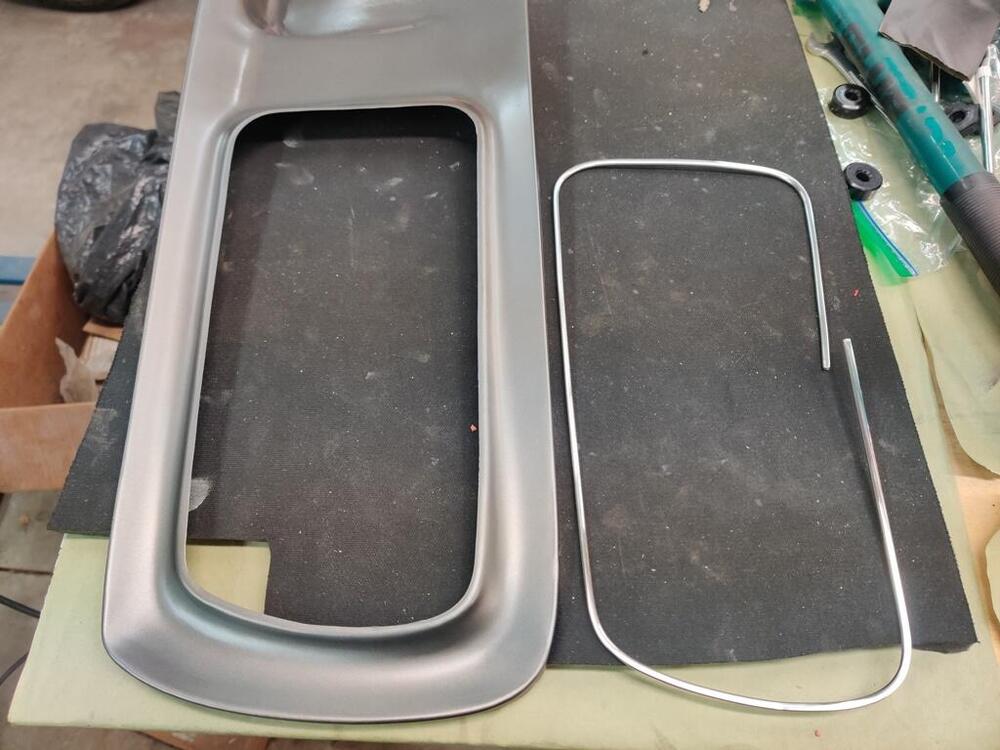
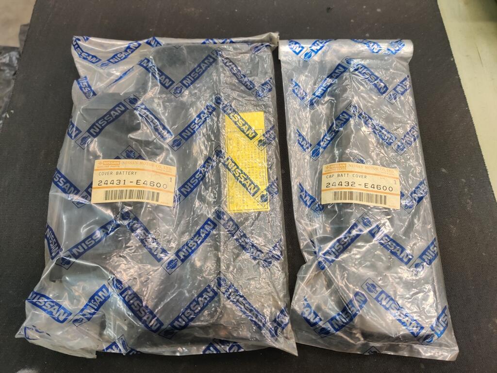
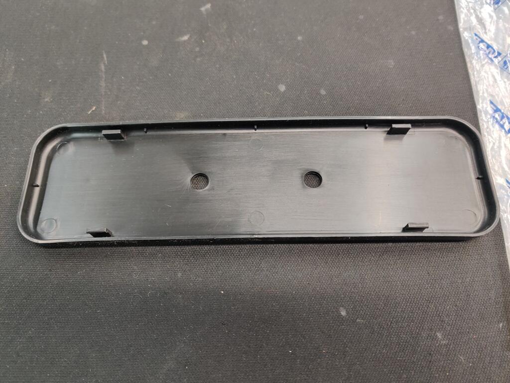
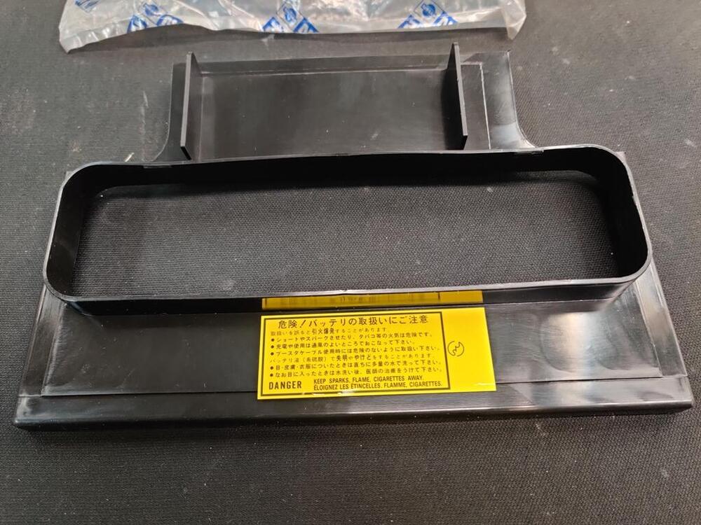
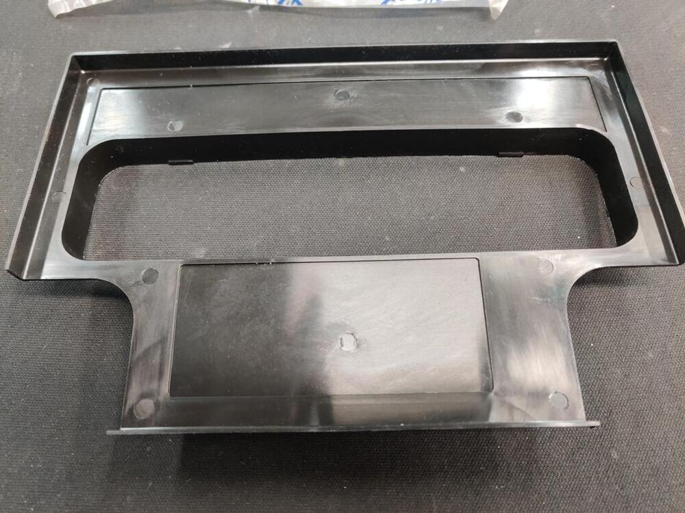
Recently, I was lucky enough to win the auction for these battery covers parts:

-
I still have painting the bolts with yellow on my list as well. And interested to know what others have used. I noted that the original was gloss, not matte, as in this picture of a fastener for my anti-roll bar bracket: Perhaps this would be a good option, but want to see what others have used. https://www.amazon.com/Rust-Oleum-7747730-Performance-Protective-Sunburst/dp/B000I1CIUG?source=ps-sl-shoppingads-lpcontext&ref_=fplfs&smid=ATVPDKIKX0DER&gQT=1&th=1
-
Looks like the answer is yes. I found this online: Georgia Code Section 40-2-41.1(b): So requirements are: You register like normal. $20/year. You get the current Georgia license plate. You keep the current Georgia license plate in the vehicle but need not display it from the rear. The historical license plate must be within 4 years of the model year, so if it's a 1985, then you can run a plate from 1981-1989.
-
Both sanding/polishing of the glass and installation in the door, dealing with alignment issues are things I did only months back. Getting scratches out of glass requires a lot of time and hard work. There are some tricks to follow for alignment. If I recall correctly, I found that getting the front sash aligned and secured first, while leaving the nuts on the back one loose was best. The back one wanted to be in a more horizontal orientation. I believe that one primarily sets how level the window is in the door - in relation to the top of the window frame. I was able to get the top edge of the window to align in parallel with the top part of the door frame. The front sash controls the fore and aft location of the window, but it also determines the path (angle of travel inside the door) the front of the window follows when going up and going down. For whatever reason, I found that I had to install a couple of thin washers between the sash and the metal inner door structure (on the left door only). That moved the front of the window outwards just a touch and fixed my alignment problems.
-
A peach! 😁 The tax for an old car like this one is $1 US dollar think. For the registration of the car on roads for a year, the amount is $20 US dollars. Thanks for the kind words about the restoration. I took it to a car event today, Caffeine and Octane, which is held at a large shopping mall parking lot on the first Sunday of every month. They claim to have 30,000+ attendees every month. Today, I was speaking with someone affiliated with the event, and he said they had over 60,000 people show up to one of these events a couple of years ago. The location is just a few miles away from my house, which is nice. I had some pleasant conversations with several people. Most who I talked with were a bit older than me, and they often mentioned having a 260Z or 240Z, or they had a friend that had one, while in college. Several used the phase "it brought back memories".
-
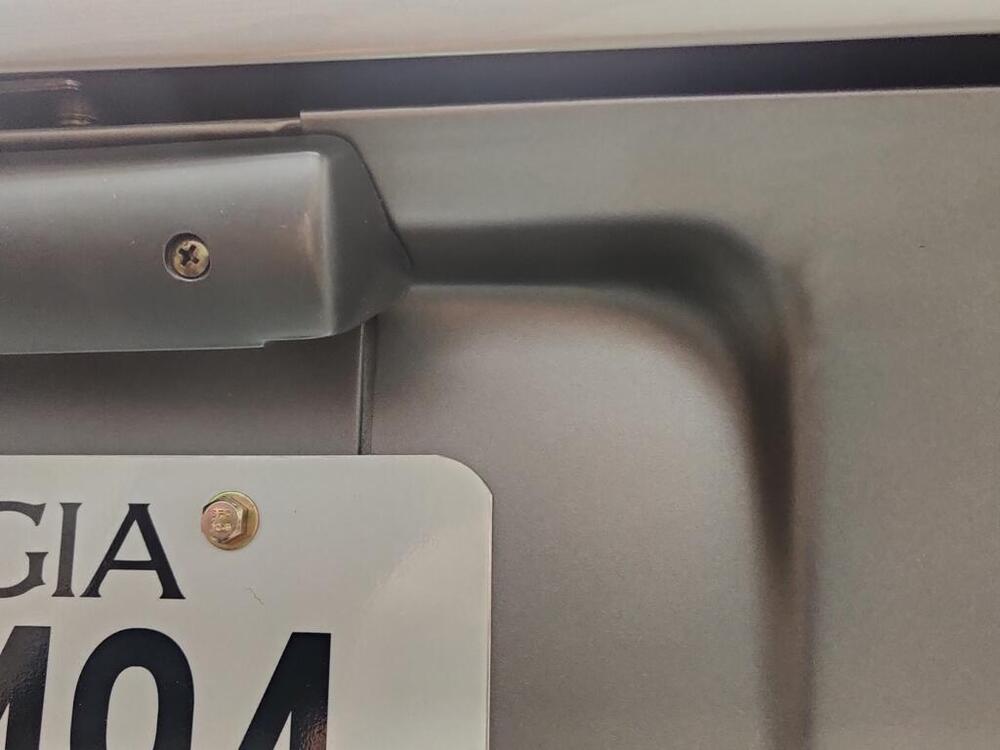
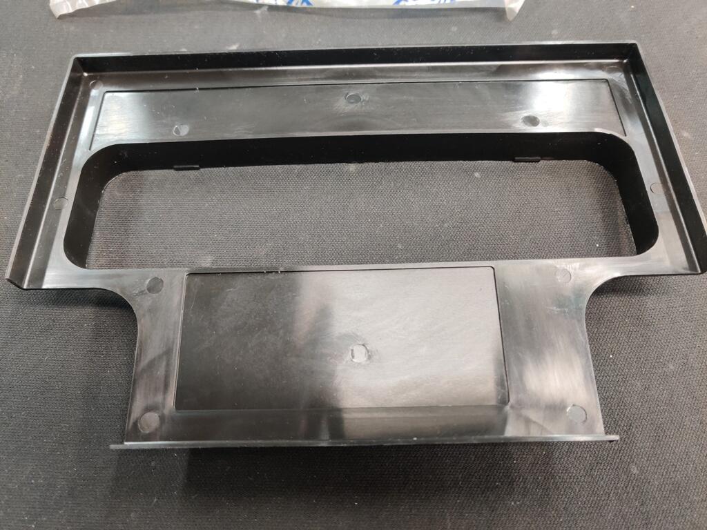
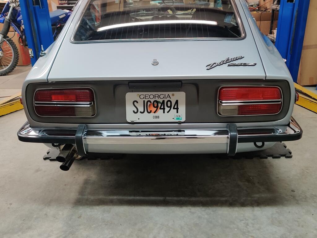
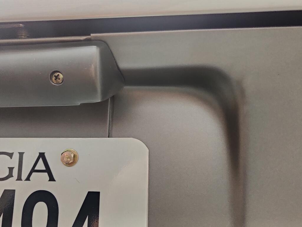
I worked on the car for a lot of hours today. I adjusted the brake pedal the proper way: I ran the bump stop all the way in, and threaded the rod into the clevis until I had the right measurement from the firewall/floor to the top surface of the pedal pad. That was 206 mm. Then I threaded the bump stop out until it moved the pedal down 3 mm. Net was 203 mm. Then I adjusted the clutch pedal the same way, setting it even with the brake pedal. I took the car for a short drive. The brakes and clutch work very nicely. When I got back, I put the car on the lift and check all around for leaks. The temperature sender nut needed to be tightened. I was getting some weeping there. The differential fill plug needed to be tightened - there was a drip there as well. The valve cover bolts also needed to be tightened. Some oil was making its way down the right side of the engine at the back corner. I also had a slight exhaust leak at one of the joints, so I tightened all the exhaust clamps. I had not tightened a couple of the clamp sufficiently. Lastly, I painted the tail light finishing panels and installed them. I used the BFM0360 Ford Dark Shadow grey (and matte clear). Comparing it to my NOS license light, the Dupli-color paint looks a bit lighter than the original color, but it is reasonably close.