inline6
 Subscriber
-
Joined
-
Last visited
-
 Well, I certainly could run a new, and completely separate wire from the coil "-" through the engine bay, through the firewall, and to the existing yellow wire to run the Speed Hut tach. But, the existing B/W and G/W wires basically already routed in the stock wiring harness from, and to where I need to go, are made completely redundant by doing so. Why not repurpose one of them and save the time and effort to run another wire? Looking at @SteveJ's wiring diagram that shows after modifications, I see that he chose the B/W that originally went from the coil "+" to the stock tach 4 prong connector as the wire to repurpose for use with the Speed Hut gauge. Of the two original wires (B/W and G/W), only the G/W wire has no purpose after this modification. I've got some other wiring that I need to figure out how to route as well. For example, I need to wire in a coolant temperature sensor and harness for dual electric fans, and the wiring for oil pressure, oil temperature and coolant temperature senders. So, I will be thinking about how best to route those through the engine compartment and where necessary, to the gauges in the dashboard. I am set for information I needed to wire up the tach - thanks to all who responded!
 -
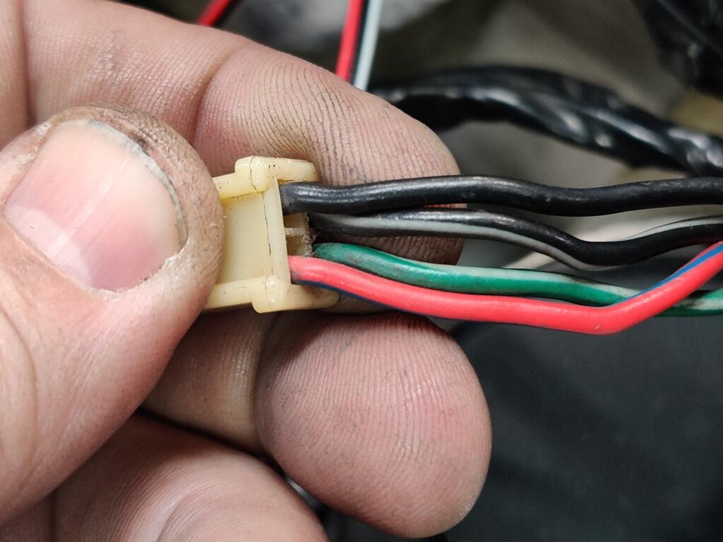
Thanks for the information. So, let me know if my rewording here is accurate: there is a B/W wire going from the ignition switch (routed through the factory wiring harness) to the Ballast Resistor. On the other side of the Ballast Resistor, there is a G/W wire (which again is routed through the factory wiring harness) to the 4 prong tach connector in the dashboard. This is the "re-route" to the back of the Tach (not the B/W back to the Tach). At that connector, the G/W wire connects to one side of the loop in the Tach (white wire with black band which connects in some way with the white wire with the red band - thus the loop). Continuing... in the 4 prong connector, the white wire with the red band connects to another B/W wire. This B/W is again, routed through the factory wiring harness and is connected to Coil "+". So... I am not using the ballast resistor any longer. I have a CraneHi6 aftermarket ignition and a high voltage coil (for mulitiple spart discharge requirements of the ignition). So, if I take the B/W wire that was connected to the ballast resistor, and connect it directly to the Coil "+", I am simply moving the B/W wire which is coming from the ignition and moving it to the coil "+"... directly. Doing so frees up both the B/W and the G/W wires (which already are routed through the factory harness). Question: could I not just attach either of those freed up wires to coil "-"... and then connect whichever of those I choose to the single yellow wire for the Speed Hut gauge? At least that way, I don't have to route a stand alone wire... and I can repurpose one of the now "extra" wires already present. My 12/70 Tach connector (4 prong) definitely has a RL wire in it (I edited my post and added a picture of the connector). That wire is "supposed to be" green according to the wiring diagrams, but it isn't. No doubt, this is a difference when comparing "earlier" 240z's to later ones. I know the gauge lighting (IL = illumination?) is RL as well (both in the wiring diagram and in my car). So, yeah... that certainly added to my confusion.
-
I am working on installing a set of Speed Hut gauges in my 240z (my "track car"). Manufactured in 12/70, the wiring for the tach doesn't match the wiring diagrams I see online. Other than power and ground and illumination wires, the Speed Hut tachometer has a single yellow wire that is supposed to be hooked up to the "coil -". It seems to me, after looking at the stock wiring, I have to not only figure out which wire is "coil -", but I think I may have to connect some of the other stock wires together in order to "bypass" the stock tach. Color legend is: blue = L yellow = Y Black = B Red = R White = W Green = G Ignoring the wires for gauge illumination, I am looking specifically at a 4 prong connector for the stock tach. Here is what I am looking at... on the left are four wires from the harness that are in the 4 prong connector, and on the right are the four wires coming from the tach that are in the 4 prong connector: Harness wiring Description Connection Tachometer wiring Description RL red with blue stripe ---- YR yellow with red stripe GW green with white stripe ---- W white (with black band on it) B black ---- B black BW black with white stripe ---- W white (with red band on it) Additionally, I am running a Crane HI6 (multiple spark discharge) ignition which also has tachometer adapter hooked into the circuit. The ignition and adapter were previously in use and worked perfectly with the stock tach. The wiring for the ignition and adapter has been untouched since the car ran. What I need help with: Which wire is the negative from the coil? Which, if any, wires do I have to jumper together with the stock tachometer no longer in place? My guesses are: Black - connect the Speed Hut yellow wire to the black wire in the 4 prong connector Connect (jump) the green with white stripe wire and the black with white strip wire (to bypass the stock tachometer) But, I am not sure. And don't know what to do with the last of the four wires (red with blue stripe at the four prong connector).

-
What you see on my car is what the body/paint shop came up with when they mixed the Glasurit paint to the stock 901 Datsun code. I left the inside of the right tool door the original paint. The original paint is a touch darker/greyer to my eye. Garrett
-
A work colleague of mine and I spent about an hour yesterday getting some video of the 240z I restored (got it on the road on Dec 31 last year). Unlike me, he has skills and talent for editing and creating videos. Have a look! https://www.youtube.com/watch?v=nQ3ieeuqjwI
-
I watched that progress over the years as he was developing it. It has been awhile since I looked at the details of it, so I am less familiar than I was at one time. I wonder what Derek's options costs (roughly)? I am sure there are various options depending on how the owner wants to proceed. But, I am sure there are some "round figures" for the head, cams, and associated cam operation hardware. Didn't see - does the head accept some off the shelf intake manifold... and header? Edit - found this https://datsunworks.com/Blog/pricing-for-the-kn20-dohc-head/
-
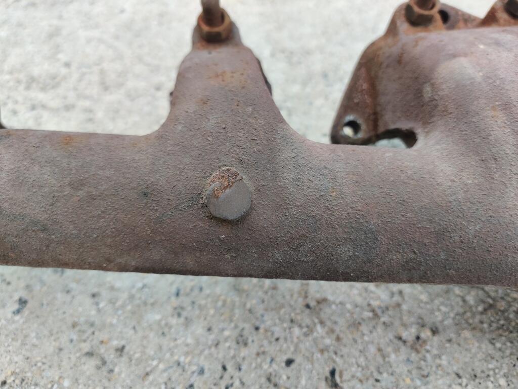
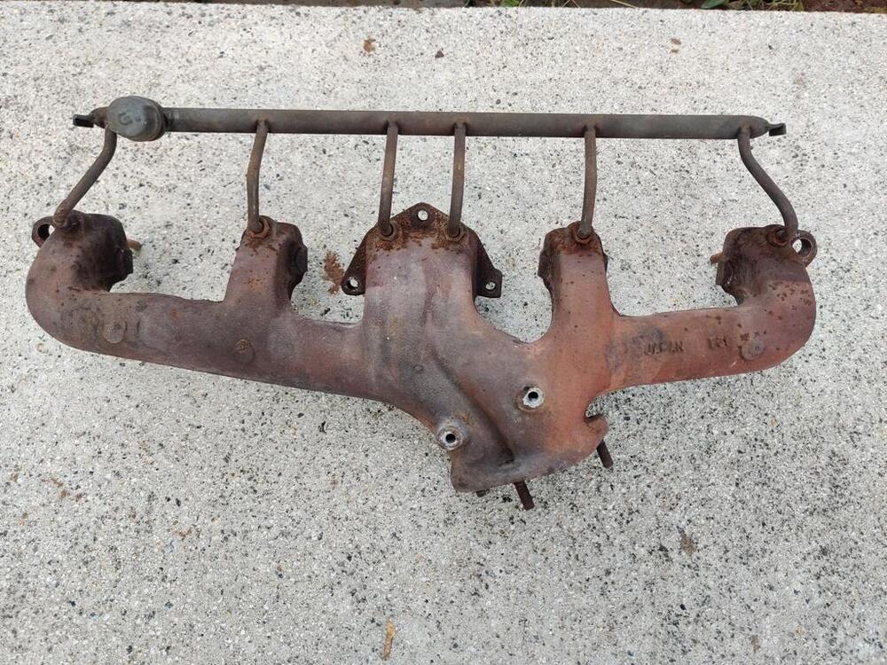
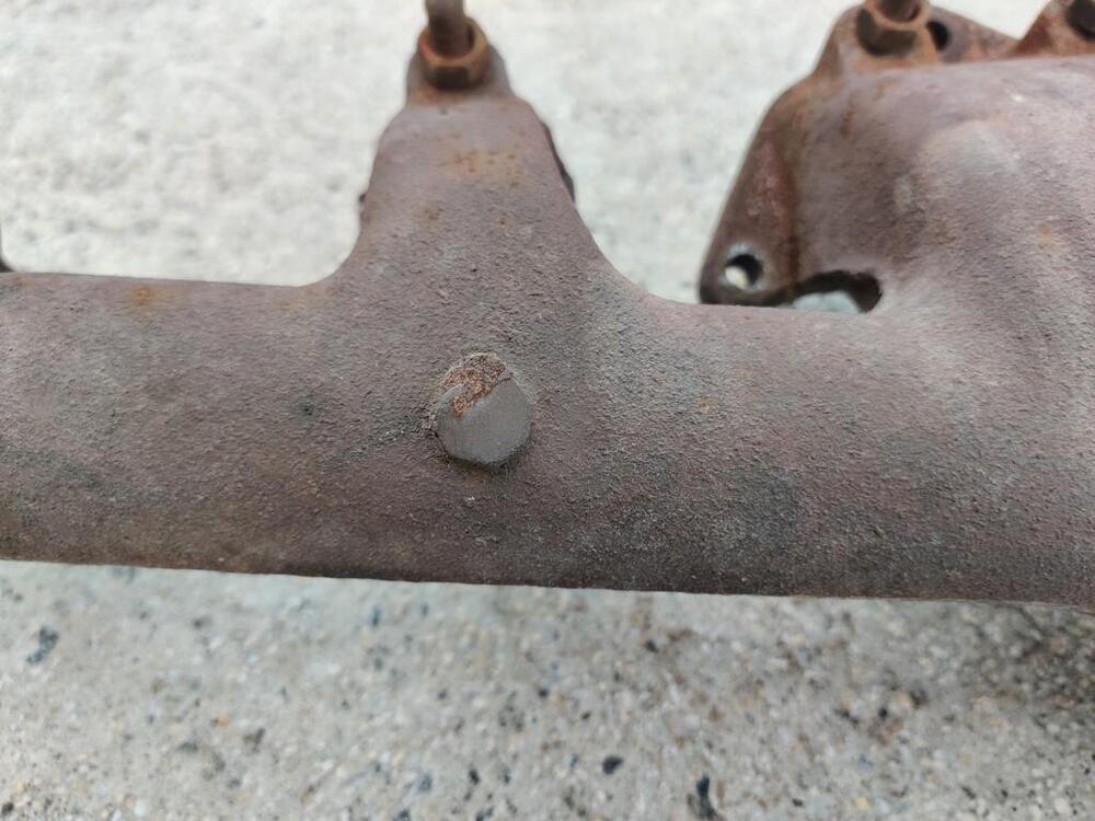
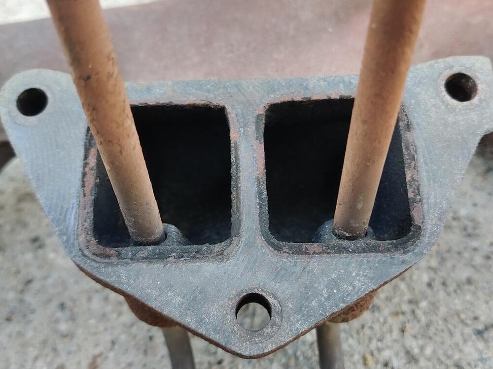
I am a bit dubious regarding the "correct" finish of the exhaust manifold. I do not think there was any kind of coating put on it by Nissan originally, so... wouldn't it just be a typical cast iron (as cast) color? If so, I think what you have there @motorman7 looks accurate. Not that this would necessarily be good reference info, but I personally kind of think it is - here are a few pics I just took of my 6/71 car's original exhaust manifold. The car was originally owned and driven in AZ for at least several if not all of its years on the road, and then stored in a garage in Colorado AZ for 30 years... Honing in on a "least rusted" portion: Machined (and not rusted) surface:
-
While this is newsworthy, it may not be available outside of Japan... or if it is, will have tariffs added to its already high $25000 dollar price (plus you need more parts to make it work). https://www.theautopian.com/nismos-old-school-hot-rodding-kit-for-its-straight-six-costs-more-than-some-whole-nissans/ https://www.nismo.co.jp/products/web_catalogue/engine_parts/dohc_conversion_kit_l-series_inline-six_engine.html https://www.youtube.com/watch?v=7Es-4hnZH5Q&t https://www.youtube.com/watch?v=CFKIAe952dc
-
Your compression test would seem to rule out anything mechanical in cylinders one and two. And yes, front carb supplies all three front cylinders, so I would not suspect a "no fuel" issue. How confident are you that the carbs idle settings for the carbs are where they should be - so both carbs flow the same amount at idle? And, when revving? Spark plugs can be dead right out of the box. I'd move plugs around and move plug leads around with them. I'd try swapping known good, perhaps from six to one and from four to two and vice versa. I think a Z engine will have a very hard time running if it has two totally dead cylinders. They may be intermittently firing a bit. So, new plug wires, new plugs, and new distributor cap?
-
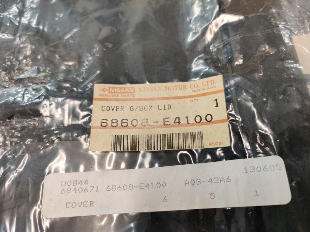
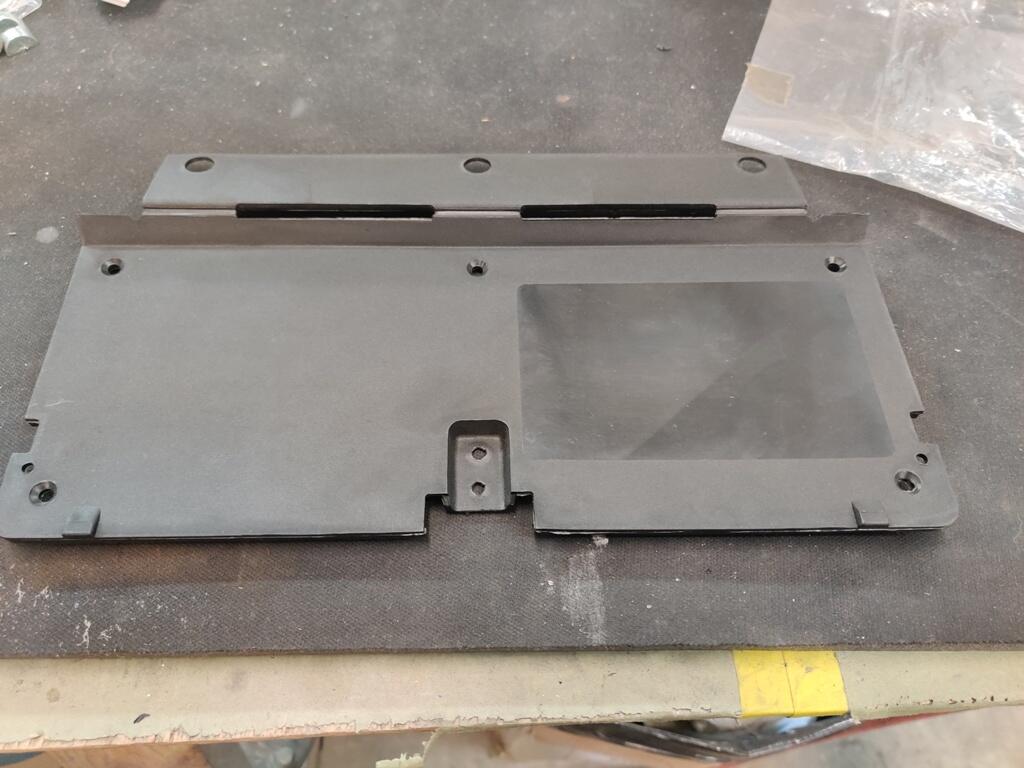
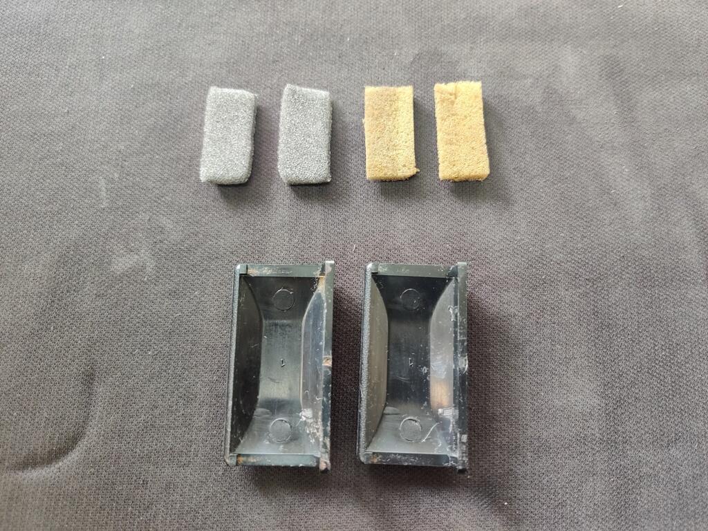
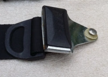
While I have turned much of my attention to my other 240Z recently, there are still quite a few things on the to do list for this car. One of them was replacing the glove box hinge/panel. My old one had broken at one of the three hinge areas. I was lucky enough to find a NOS one. Having recently replaced the decal on the original one with a new decal, I had to procure another new decal, and put in on this new panel. I still have some alignment issues to work out before the glove box will shut properly. The Vintage dash that is the car requires a bit of trimming of foam and vinyl on the lower edge of the glove box opening to allow the hinge to operate properly. Another small item on my list was to install these plastic seat belt buckle trim plates (old foam on the right, new on the left, which I glued to the center backside of the trim: These go here on the 1971 belts: I used a heat gun to warm them up quite a bit before snapping them into place, which went without issue thankfully. I still have a bunch of details like this that need to be completed. I would like to swap out the headlights bulbs for some other Koito H1 type ones that I found which look more like the originals. There are various other markings I'd like put in place to replicate factory ones (paint markings). I also would like to get the original wheels refinished and get some stock sized tires mounted on them. The original hub caps that I have are very nice, but if I can get better results with the paint color experimentation, matching the original much better than my efforts thus far, I will refinish them. I still haven't done anything to address the lean condition that I am experiencing. So, that is still on my list. After about 4 rounds of pulling the valve cover off to adjust the valves (the valve noise was much more than I can recall with my other L series engines), I figured out part of my problem. I have generally been adjusting valves with the engine cold, but sometimes when it was kind of warm as well. I was sure it would tighten up as the engine got warm. What I have found instead is the the lash clearance actually grows a bit when the engine warms up. The specification for my camshaft is .006" on the intake and .008" on the exhaust. I started off with setting the clearance at that spec with the engine completely cold. I then found that the lash was a bit larger with the engine lukewarm and a bit larger still with the engine hot. Seeing this, and after resetting lash a couple of times prior with no improvement, I decided to use .005" and .007" while the engine is cold instead. With that I achieved notable improvement.


-
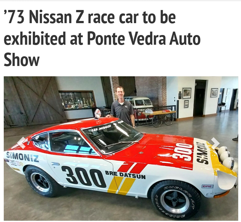
https://www.pontevedrarecorder.com/stories/73-nissan-z-race-car-to-be-exhibited-at-ponte-vedra-auto-show,150339
-
I really like this stuff for all adhesive needs: 1 Gal. DAP Weldwood HHR Contact Cement You may have to clean some weatherstrip of its "mold release" before trying to glue it in. A little lacquer thinner on a rag and a few wipes on the surface to be glued is all that is needed. For door weather strips, I use an acid brush, start in the sharp corner at the top, back of the door. You can do it in sections about 18 inches long. Just apply adhesive to both surfaces, wait about 3 minutes, and then press and stick. It is going nowhere after that.
-
It is buy it now for $40k. I told him to emphasize that the original mileage is 51k and to add some pics of his documentation... pics of the various VIN plates and VIN on the firewall, and pics of the engine number on the block and the E31 on the head. I see he has added the documentation and the engine compartment tag already. I know the market is a lot softer now for these than it was, but I think it will sell for the $40k.
-
I have been watching this one for a few weeks. Couldn't get it out of my head, as it has an extremely clean and mostly original interior. Miles claimed at ~51k. Since it is only an hour a way, I went to look at it. The current owner is a son - this was his father's car. He has some documentation going back to 1972 which does have mileage on it. He has two or three documents - enough to support that the mileage is accurate. Also not clear in the listing is that it is a matching numbers car - original engine and head, as well as the original 4 speed. The original spot welds are present even in the rear fender wells at the bottom (rocker). The car has never had any rust through. He also said he has the original hardware (replaced with stainless) and the original front, lower panels (left, center, right). The paint is daily driver grade. In my opinion, to take this car to the next level, it would need a full exterior and "door jamb" repaint. Floors and hatch area and engine compartment still have the original silver paint. eBay1971 Datsun Z-Series | eBayFind many great new & used options and get the best deals for 1971 Datsun Z-Series at the best online prices at eBay! Free shipping for many products!
-
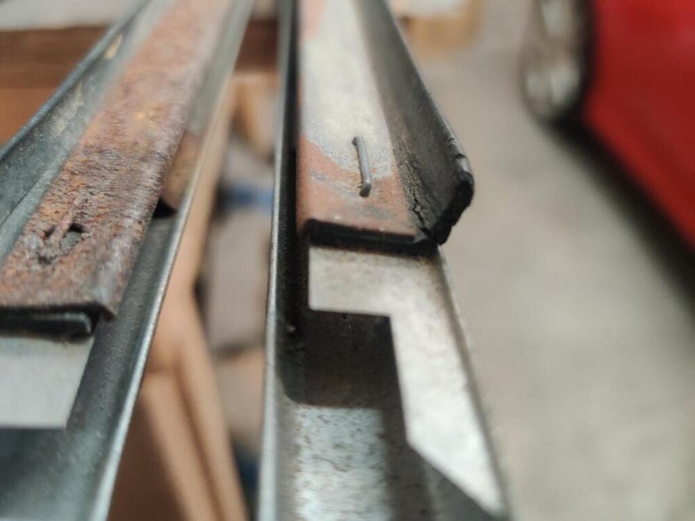
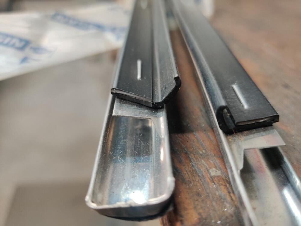
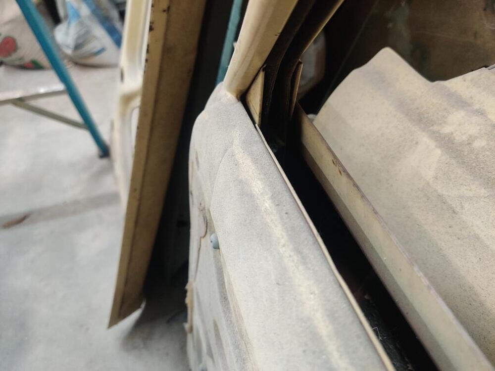
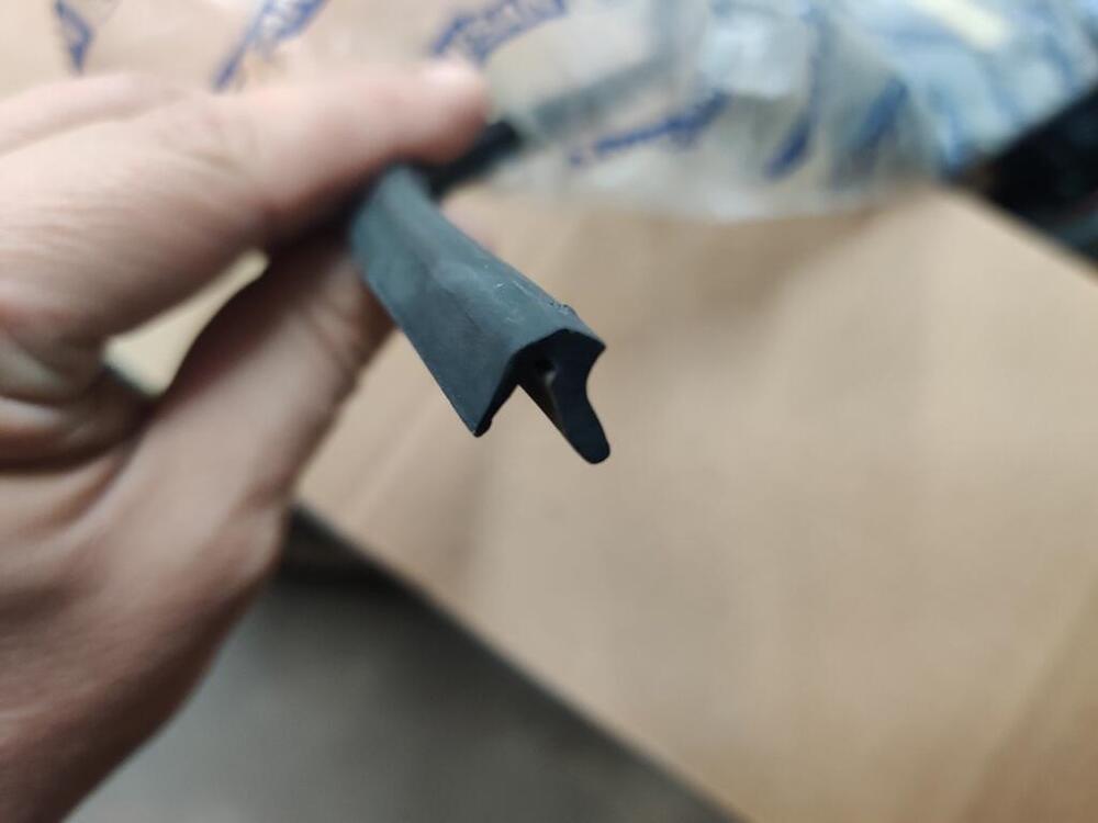
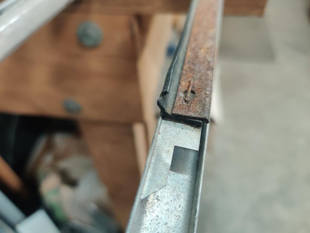
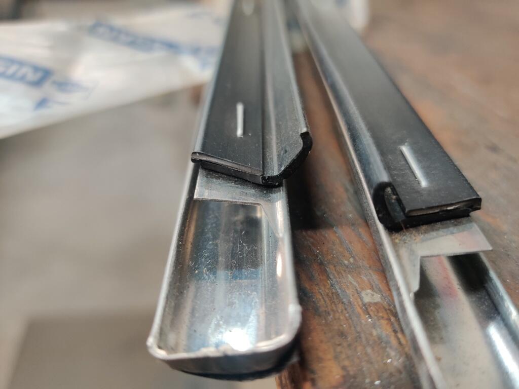
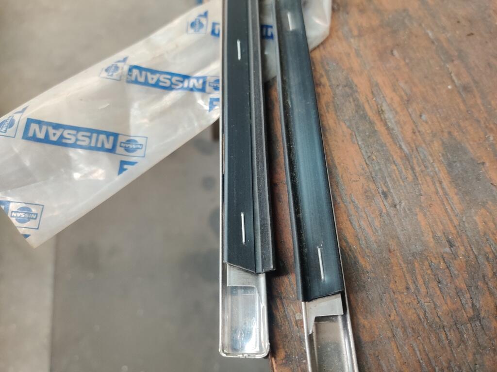
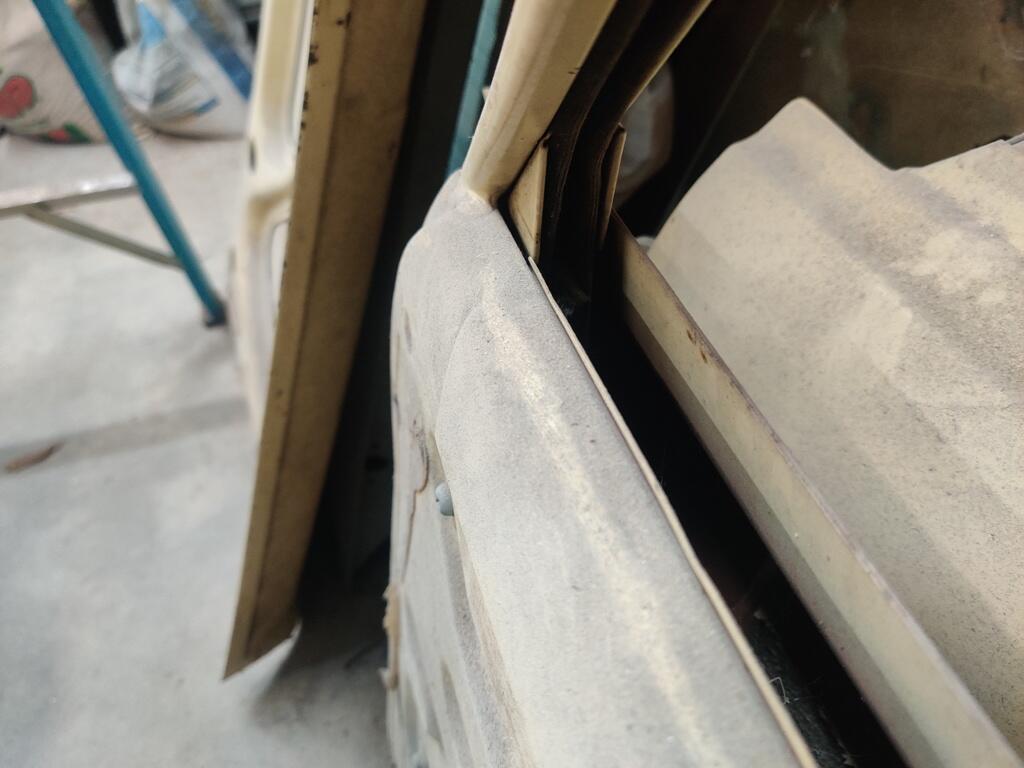
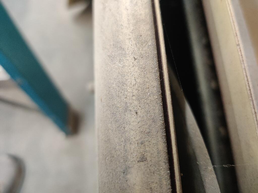
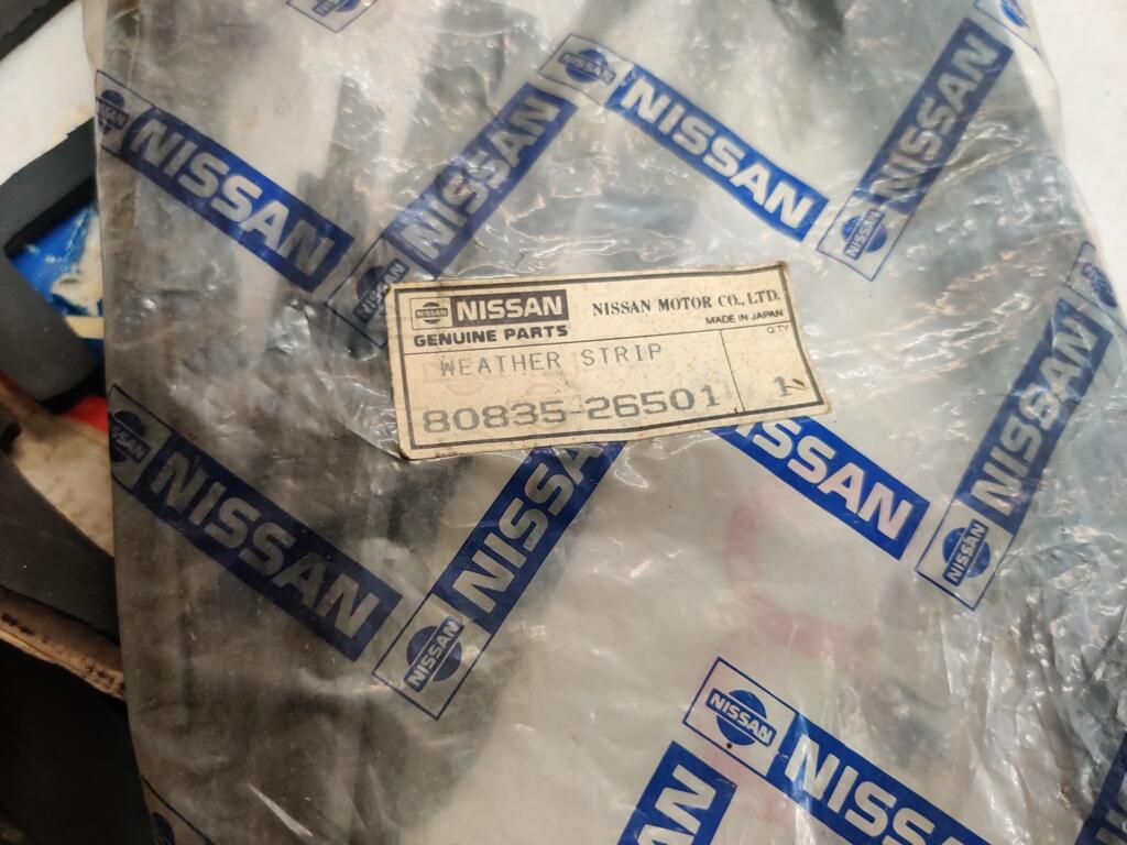
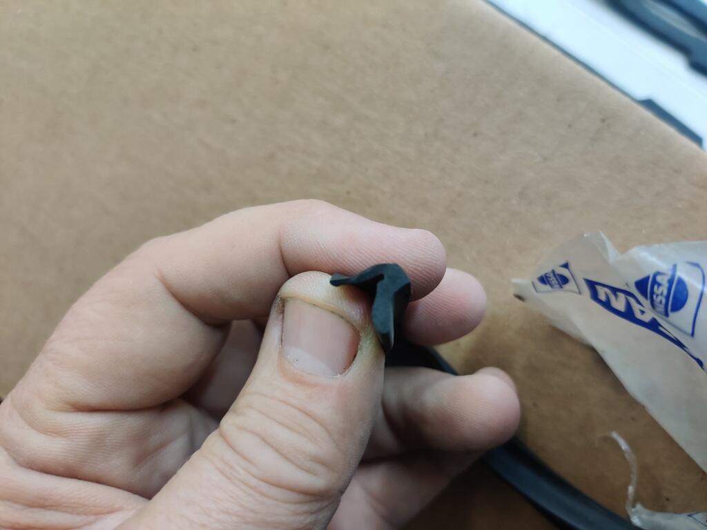
The first two pics are some 510 4 door outer door/window trim pieces. The second two are 510 2 door outer door/window trim pieces. The rubber looks to be the same shape to me for each of them. The next two pics show the groove on the inside top edge of the door where the inner rubber w/s goes. It is a simple u channel. The last three pictures are of NOS inner rubber weather strips for the 2 door. The front and rear doors of the wagon should use the same inner and outer w/s from a design standpoint, right?