Captain Obvious
Free Member
-
Joined
-
Last visited
Everything posted by Captain Obvious
-
 I support this message.
 -
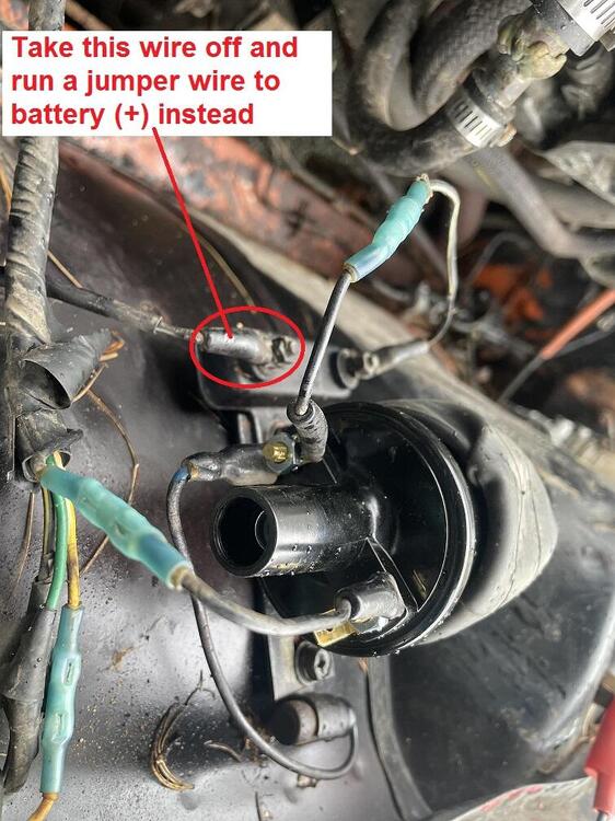
The 240s run the ignition signal THRU the tach, so no... The car (in stock wired configuration) will not spark unless the tach is connected. If you want to hotwire the system and bypass the tach and much of the original wiring, try this... Take the wire off the front side of the ballast resistor. Run a jumper wire from that front end of the ballast directly to that "+" battery terminal. Crank the car and see if you get a spark. If you get a spark, your points are working correctly and the problem is elsewhere. Here's a pic of what I'm talking about:
-
Thanks @zed2. Those seat brackets sure are clean and shiny!!
-
Honestly, with all the hacked up wiring and splices and stuff, I can't tell if yours is even close to correct or not. But my assumption (based on the fact that it won't spark coupled with the cut up wires and splices, etc) is that your ignition wiring is not correct. Can you strip the G/W and B/W mystery wires back a half inch and check voltages to body ground? Negative of meter on body ground and positive on B/W. With key off, on, and start. And then do the same thing for G/W. Off, on, and start. What happens?
-
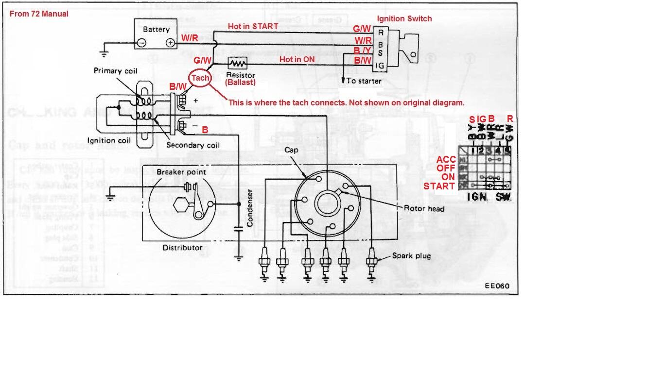
Both the G/W and B/W are involved in the ignition. Here's the wiring diagram for the ignition system. This was originally created from the 72 manual, but 73 is the same:

-
Gotcha, thanks. So that indicates an issue for me.... Someone in the past has replaced my LH seat with a RH seat. Probably because the original LH seat was worn and it was simpler / easier to find an un-worn RH seat (in the US). So now it sounds like I should find a LH seat.
-
Good deal. I hope karma shines your way for your contribution to the community.
-
Got it. I'm not a body guy, and I thought you were saying the joint mandated lead (specifically). It does not require lead... It requires a filler, and they chose lead. Thanks.
-
I assume you've been overwhelmed with the responses to this ad, right? My understanding is that those wheel covers are worth some $$. If you're really, really intent on just having them disappear, let me know and I'll be more than happy to cover the shipping!!!
-
Woot!!! Hopefully we can get them together! Archie is looking forward to it!
-
Quick diversionary question... The tilt adjust knobs on the early cars should be facing each other on the inboard center console side, and not on the outboard sides by the doors, right? In other words, this would be a right side seat, correct? And the left side seat would be a mirror image? :
-
Not sure I understand this part... Why would the complexity of the joint mandate lead loading? I get that a complicated joint like that would require "some sort" of loading, but why specifically lead? Couldn't they have used polyester filler instead of lead? In other words, is there something mechanically different about using lead here instead of a plastic filler?
-
Nice work.
-
Wait... I know. You're HOT, right??!
-
That could certainly be the case. I don't know how Datsun handled their part number replacement scheme, but where I came from, we would have probably used a different P/N if we changed the mold. Especially if the production floor processing was different between the two. So picture this... On the production floor, the early early one required the output port markings to be ground off and re-stamped. Then they changed the casting and the requirement for that processing became unnecessary. You would need a way to document that and communicate it to the shop floor. A new part number and accompanying new work order paperwork would be a good way to handle that.
-
Gotcha. And a couple comments about that spot / glazing putty: It's solvent based and because of that, it shrinks a lot as the solvent evaporates. Thin coats only to build up a deeper wound. Also it will likely etch into the PVC that the center console is made out of. That PVC is low on the chemical resistance chart. And lastly, be aware that filler has no mechanical strength on it's own. Think of it as "spraying a whole bunch of coats of sandable primer". (If that makes sense. ) I've found that JB weld sands OK with the correct low load paper.
-
Thanks bluez. So it definitely looks like between 7/70 and 12/70 they changed the markings from stamped-in to cast-in. Haha!! Another detail to look for on the early cars for authenticity. Stock class judges be aware! "It's got an early style M/C." "Yeah, but it's not an early early style."
-
I like it. It's not a particularly stressed part. I say use whatever to make it hold together. Out of curiosity however... If you found a donor, why not just use the whole donor? Was it damaged in a different location or something?
-
Got it. So it sounds like choices to fill that large visible joint after welding was either lead or plastic filler? And they chose the lead.
-
Gotcha. So what is the fixing method? Are there spot welds that do the mechanical joining? I (thankfully?) haven't been in that deep into the body.
-
Awesome, thanks. So it seems the F&R markings were stamped into the masters early on, and then sometime between 7/70 and 12/70 they changed the mold to cast the F&R markings directly into the body. Makes me wonder what was on those early castings before Datsun ground it off. I'm thinking that the circuit locations were stamped with the original "R" being towards the radiator and the original "F" was towards the firewall. Then for some reason (safety or testing of some sort?) they decided at the last minute to change it. Would have been an interesting decision making process. Would have loved to be there to hear part of that.
-
Anyone with an early car have any input into the stamped vs. cast-in "F" and "R" markings? I have strong evidence that this master cylinder was on the car when it left the factory in mid-1970. Or has everyone else had their master cylinder replaced somewhere along the way?
-
Agreed. I wasn't there when they designed it, but I don't see that soldered joint as "flexible". I'm thinking they needed to join two major assemblies in an area that is extremely visible. An area where spot welds would have been unsightly. Maybe they thought the solder joint would not only be strong enough, but it would be much easier to hide? Maybe they just couldn't come up with a way to do a spot weld there because of access? But who am I to say? I wasn't even there.
-
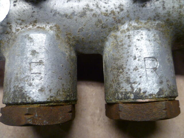
And for comparison, here's the one bought on ebay by @inline6. Note that the "F" and "R" markings are cast into the cylinder body as opposed to mine which are stamped. Now, there's no telling where in the chronology this ebay body came off the assembly line, but it was clearly at some time after they decided where "F" and "R" should really be: I'm thinking that Datsun changed their minds very early on? And then there was a revision to the casting to cast the "correct" locations into the body without having to grind and stamp?
-
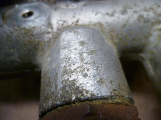
And while I'm posting pics.... Anyone have any info about the markings of "F" and "R"? I have high confidence that the master cylinder I have here is the original one that came from the factory mid-1970. Note that the "F" and "R" circuit markings are STAMPED into the cylinder body, NOT cast in. In fact, if you look close, you can see that there was some sort of grinding that took place before the "F" and "R" were stamped. Like they ground off the original marks and restamped the master with the front and rear as documented on the early cars. Here's what I'm talking about... If you look closely, you can see the grinding marks and the stamped "F" and "R":