


zKars
Supporting Member
-
Joined
-
Last visited
Everything posted by zKars
-
@Randalla, please message me. Thanks
-
I was thinking of getting a Greenlee punch set to make easy round blanks. I noticed when I cut my square coupons into a hexagon, there was less distortion. I haven’t actually tried to start with a truly round blank to see what happens. I’m happy with what I’m making. And yes, I have seen the youtubes of people spinning HUGE aluminum disks in HUGE pots pans and other receptacles. Very long lever arms and very large lathes spinning them. Very impressive. I will not be trying that, even on a small scale on my lathe. I see another 3 week boondoggle coming up....
-
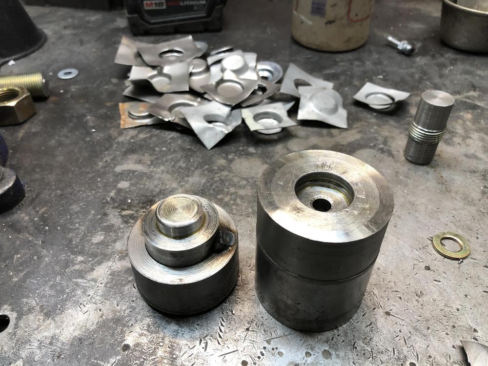
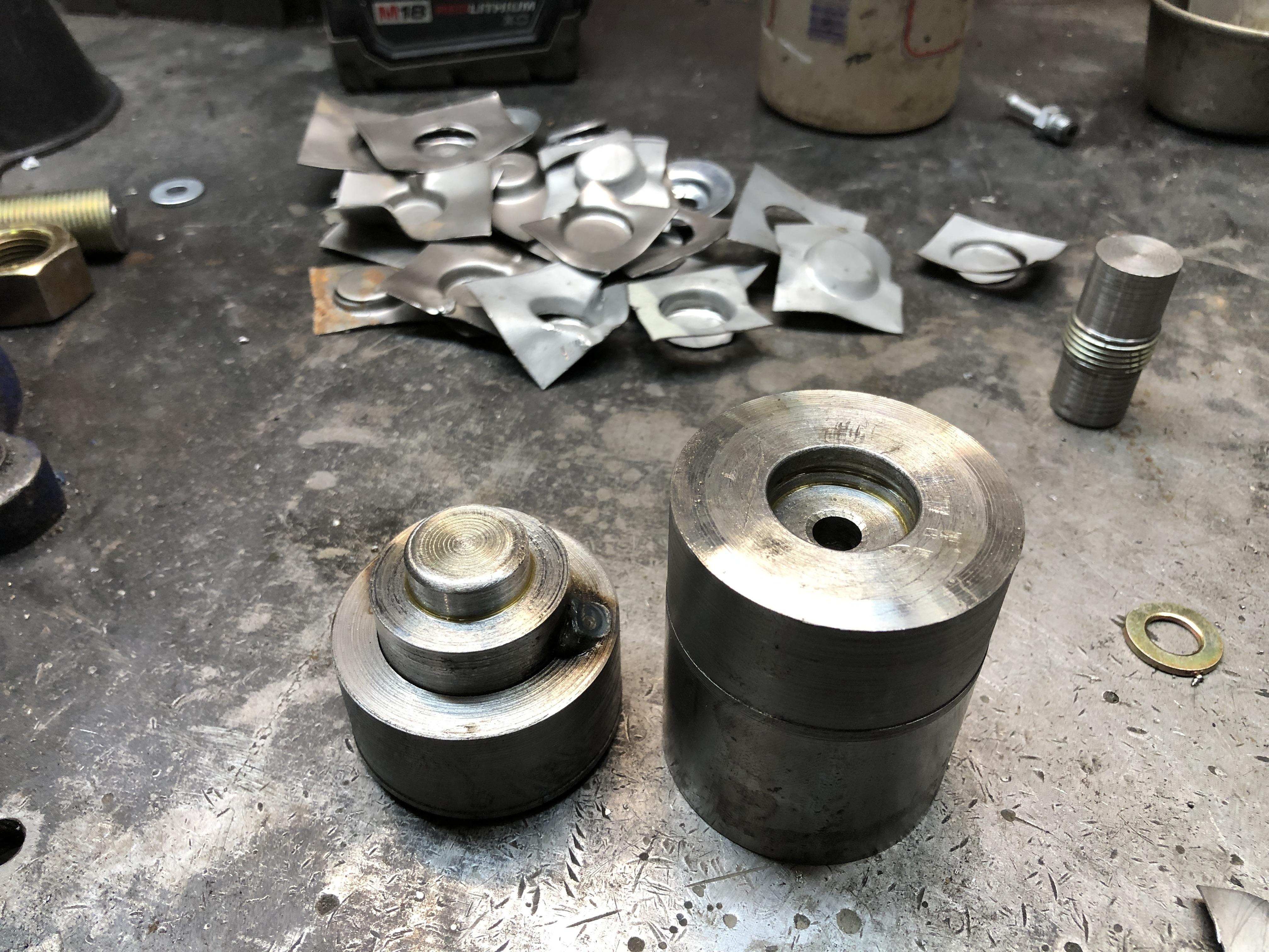
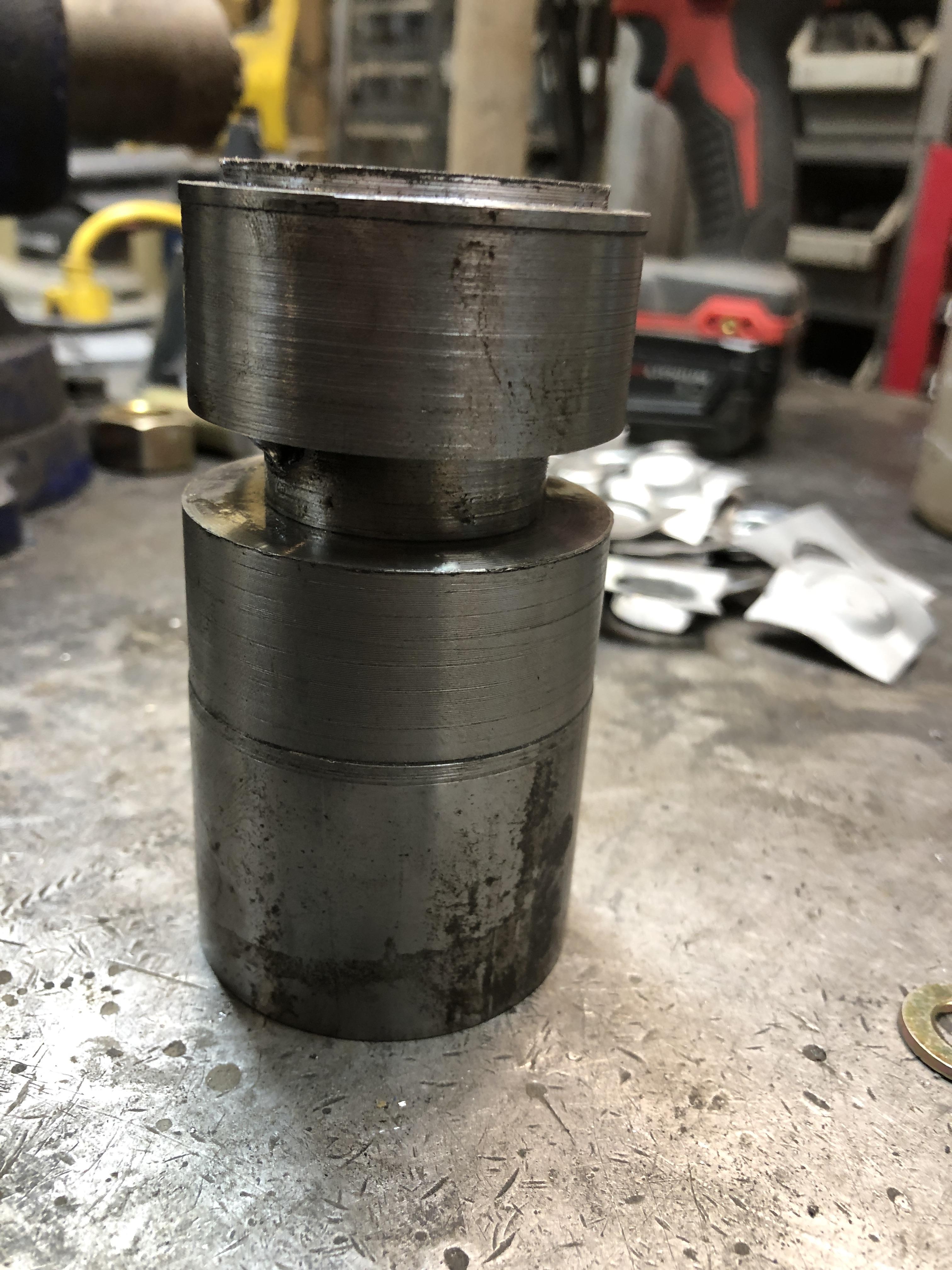
Quick update. Lot going on at home right now. I have a good solution going. Made the first group of 20-ish. Size is great, appearance comparison to original is pretty good. Drilling the hole after the initial forming is the only option. Any hole in the piece to start with is a) too hard to center, and tears out immediately, pretty much like the fender washers. Using a center hole in the FM part of the die makes drilling the hole in the middle very simple. Once I got the dies centered to each other consistently, I can make millions of identical little wrinkled creatures that only take about 175 finalization steps each. Easy peasy. I’ll have pictures to post of the whole process stages later in the week.

-
Nice and simple. As long as the oil streams all aim at the right place, it’s all good. If “I” were advertising such a thing, I would be posting video’s of the spray patterns at 10 psi (Idle) and 60 psi (operating) to give such a critical piece some semblance of trustworthiness.
-
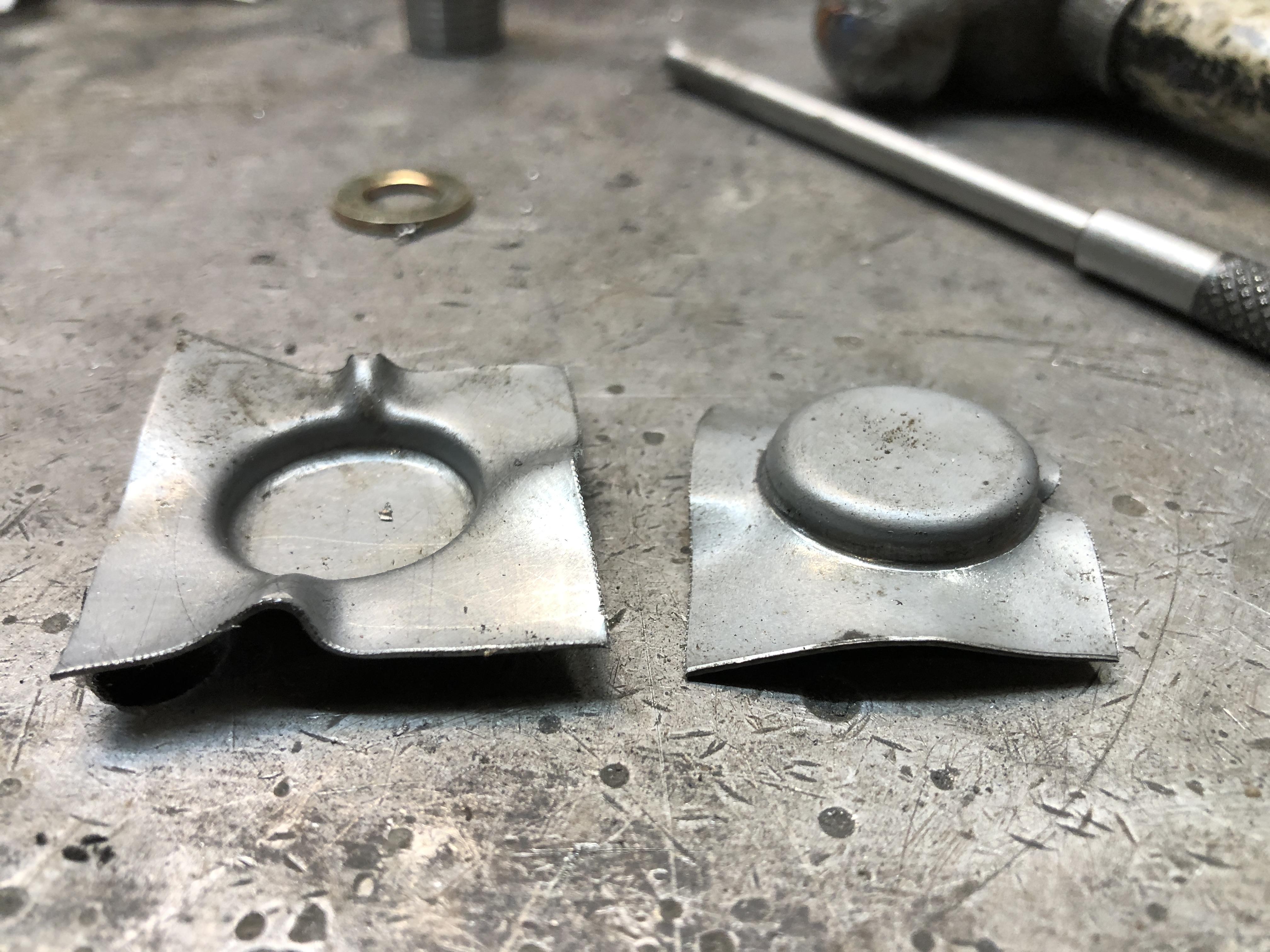
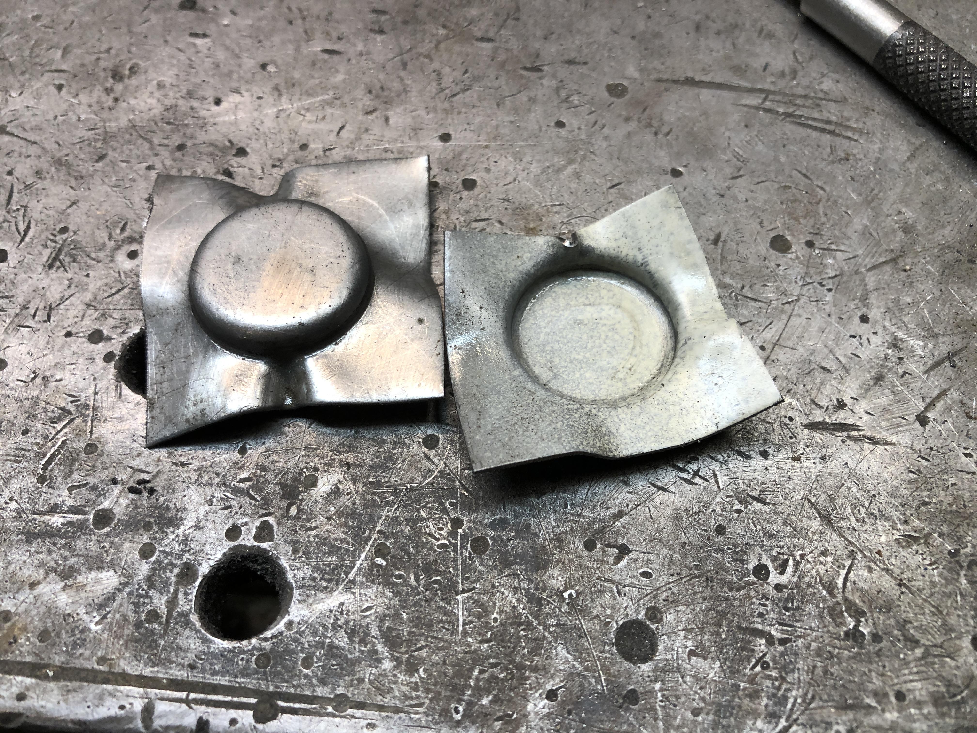
I initially tried using a fender washer that had a 5/16 hole, and die parts that pass through the hole. Seemed like the right thing to do. This didn’t pan out very well, as the distortion that happens caused the material to rip around the hole. I now have a 5/16” hole in the female side of the die, so I’ll use that as a drill guide to put a hole in the part after it’s formed. I measured the original washer base thickness. It is as suspected a bit thicker than the walls, at 0.050. 18 gauge sheet metal is 0.048, guess that will do.
-
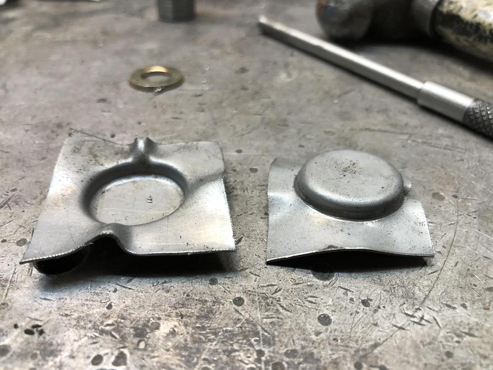
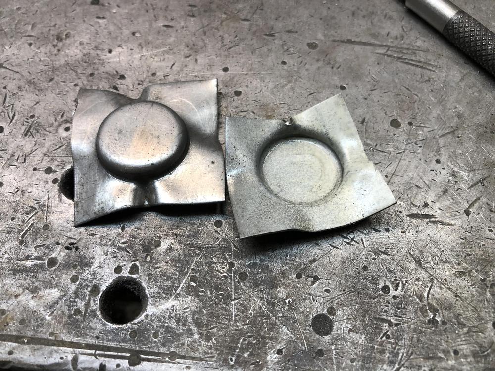
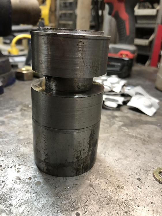
Three guesses what I did today. Dang process is very sensitive to several parameters. Centering of the dies turned out to be the biggest challenge. Lubrication was also a real helper. Corners are radiused. Once I got it right, I can duplicate . Twice anyway. I’d like to get the depth of the female die just right, so it stops and makes a nice flat bottom. It’s a bit deep at the moment Notice the pile of test pieces in the background. Next tricks are drilling the 5/16 hole (starting with 5/16 fender washers did NOT work) and cleaning up the excess. I plan on drilling the hole first, then using a 5/16 bolt and nut to make an arbor to mount it in the lathe, the clean up the flash there. No doubt there will learning moments along the way with that too. I currently only have 0.035 thick tin, the original washers have a .045 thickness at the turned up lip. Will have to go shopping Monday. I will have to reduce the diameter of male part of the die, to make room for the thicker material. I have .035 gap in the dies at the moment to match the material. They feel like they would be too thin and cheap feeling with 0.035 material. So making is possible it seems. More news on Monday.
-
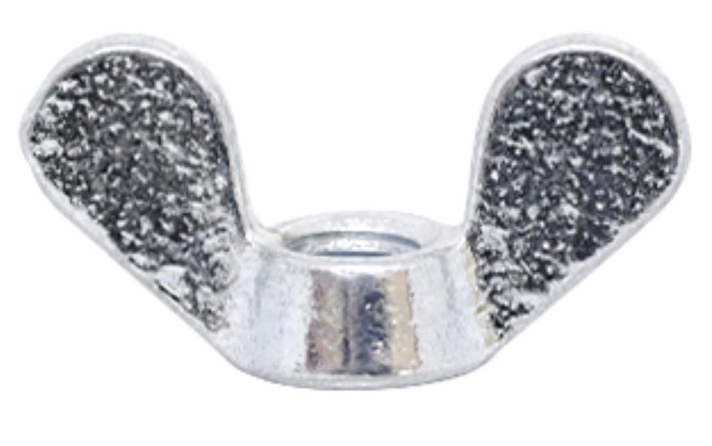
Well that was too easy. A lesson on hardening, a lesson on materials, a lesson on drawing, what more can a guy ask? Thanks! Now I have to go try. I got the project car in the garage easy, parts gathered, getting all gung ho. Gotta slow down and turn a little stuff on the lathe first and take my time. Think I’ll use 5/16 fender washers as the raw materia (assuming they are 1” or more in diameter)l and put a 5/16 nose on the male side of the press and a matching 5/16 hole in the FM side of the pocket to guide the process. Need to make a nice flat bottom 7/8 hole for the FM side to get started. Hope the radius of the corner is nice and tight like the originals. Should be able to press hard enough with my 15 ton press. Fun! Looking for hardware, I even found some nice metric wing nuts with the right kind of “mickey mouse” ears that look like the originals. Apparently they are “German” style... Maybe I can work toward making replacement for the whole bolt assembly.
-
I've contacted Randalla and asked if I can help with supplying my version while his is un-available. I'm awaiting his reply.
-
Sure, but I’d like you to show me how, not so much do it for me. I really need to stop getting distracted with fun little projects like this and get the next 510 in the shop and finish it’s resurrection. Heat treating. Heat until yellow, then plunge in oil right? Then call 911. I’ve been watching those knife maker shows....
-
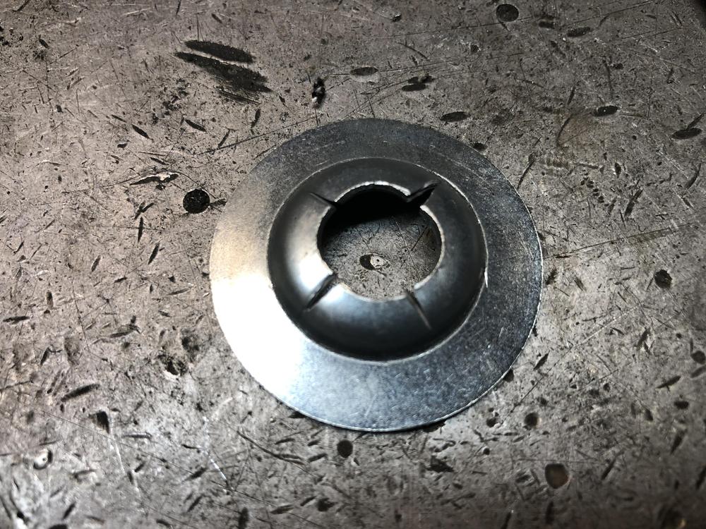
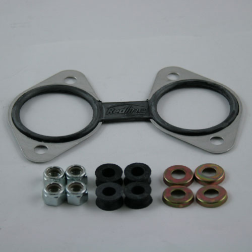
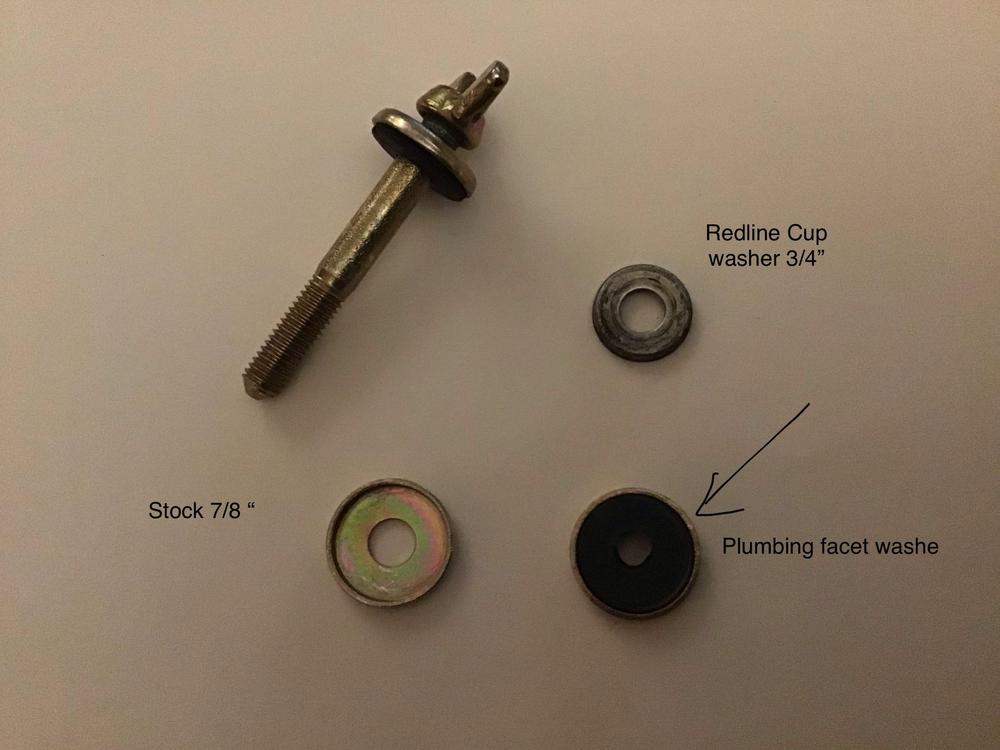
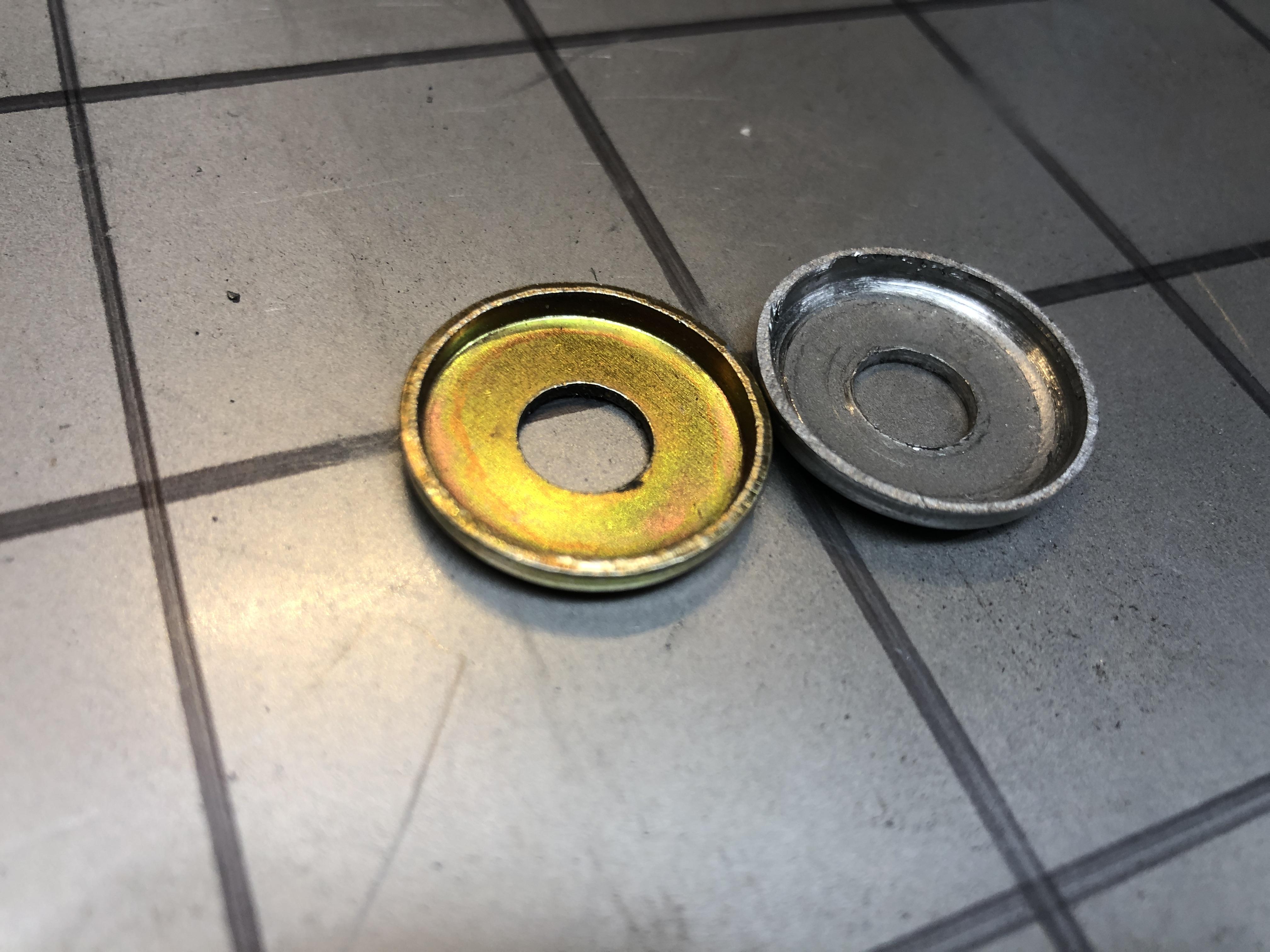
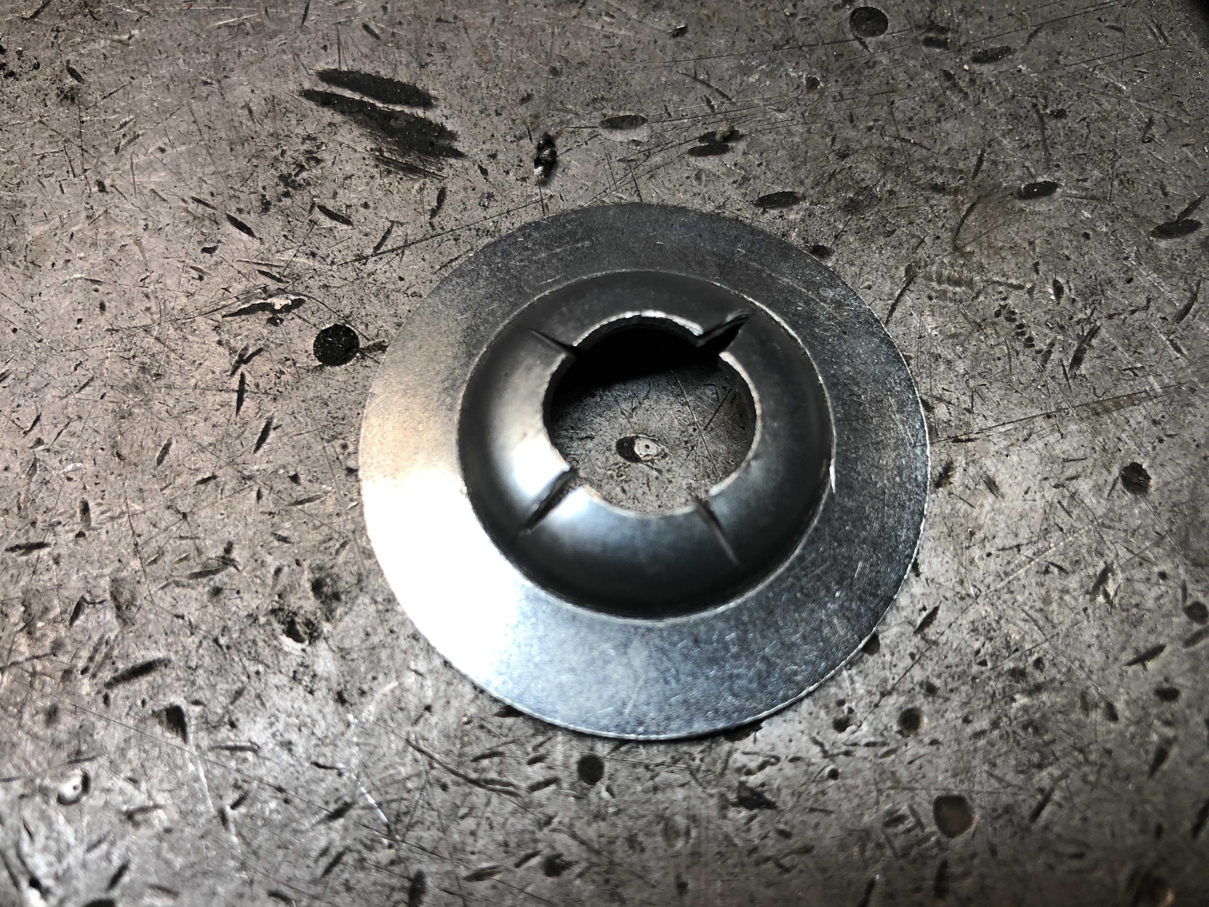
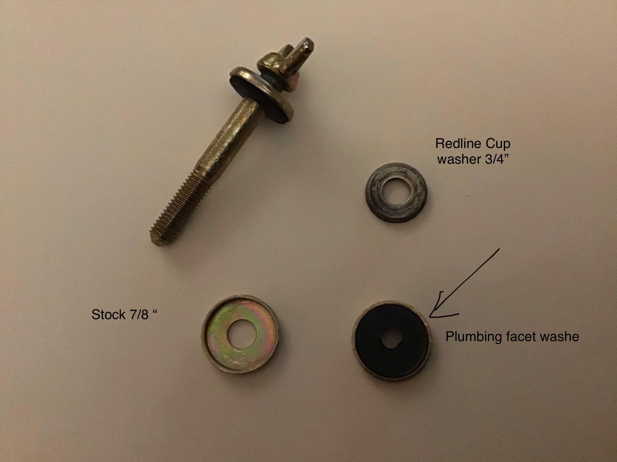
I have a decent little collection of the long wing bolts and the mating long “nuts” they thread into, but the one part of this assembly that I am lacking in is the little cup washer with the rubber grommet underneath. Been hunting for a replacement in the generic hardware world and have come up virtually empty handed. About the only thing close is from RedLine Performance in Auzzie land. Many of you may have touched these over the years if you’ve done side draft carb installations. Redline 52-110K Those cup washers lower right are perfect, well, they are 3/4” diameter while the real ones are 7/8”. There is one in the first picture top right. I contacted Red line and they do sell the cup washers separately, in fact they make them in-house! The Sku is 52-571B $2.58 I even asked them to please make them 7/8” See what they say. I had previously found a plumbing washer that duplicates the rubber washer in the stock cup washer so that part is easy. Now this leads to three things. First, everyone go search the interweb and see if YOU can find a supplier of cup washers. Second, Caption Obvious, machine me up a die to press flat 1” washers into lovely 7/8” cup washers! Simple. Third: You hoarders with a thousand of these already, contact me. I need a dozen.....
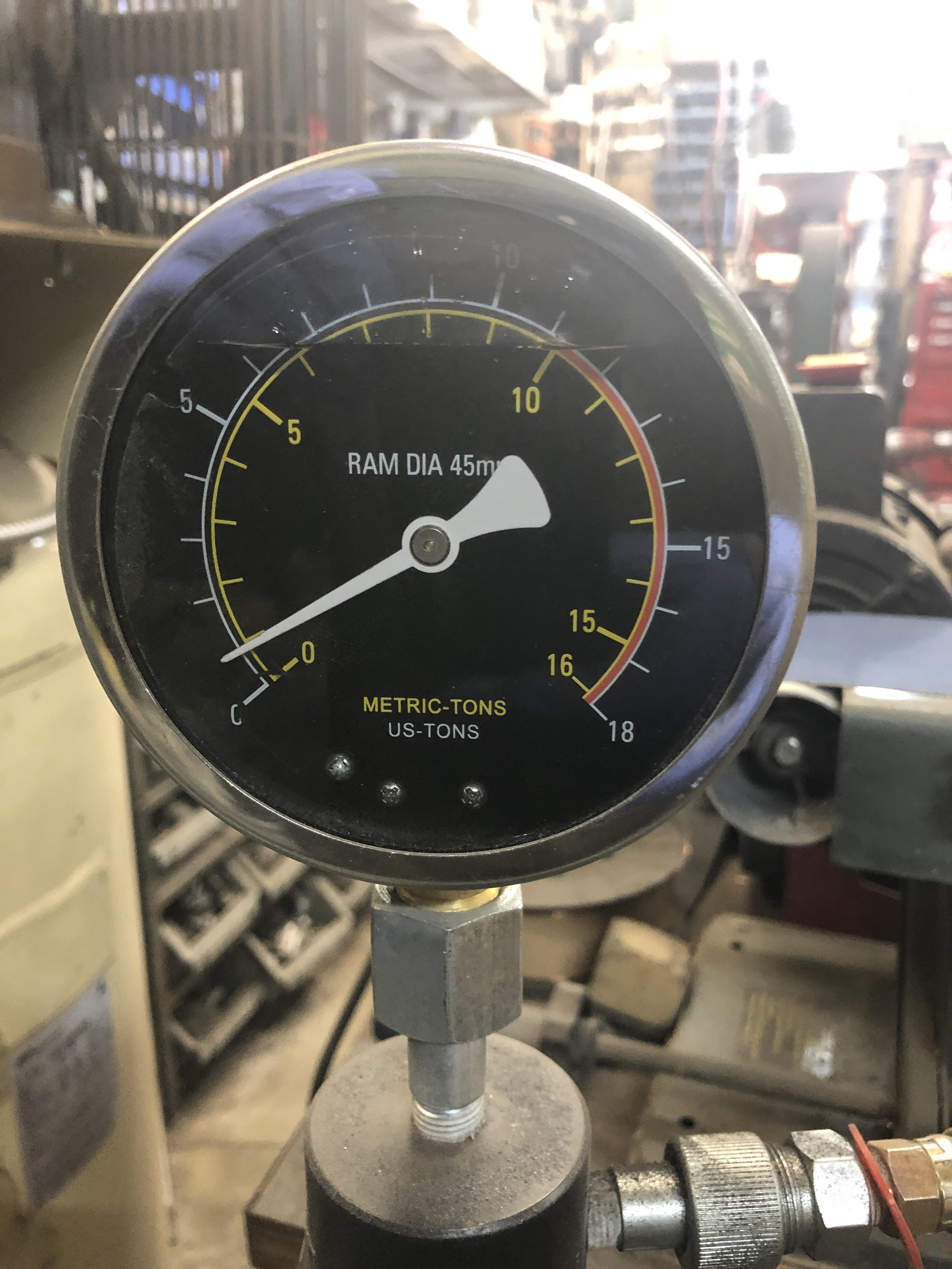
 WELL I finally got a chance to take the “new” (to me) fancy hybrid extra yummy tranny out for a drive tonight. The roads are clear here, temp is +5C, beautiful night for a cruise. I have to get this thing out of the shop tomorrow anyway to get the next project car in there, and we have a good cold snow dump coming this weekend, so now or never. I am happy to report the trans works very well. MUCH quieter over all than the old rattle box (better be with new bearings and such). All gears change easy, new synchros are doing their thing just fine. Up and down all gears. That fancy 62mm front bearing in my gingerly machined out bore seems happy, but only time will tell about how well the counter shaft bearings stand up to the abuse I will be giving it over the next few years. Even the reverse light is happily coming on with my modified shift rod with the 4 speed bell housing. Remember this is the one with mixture of a 720 truck ratio’s stirred with a 4 gear set from a close Ratio ZX 5 sp. The idea was that it gave a 0.65 ish 5th while retaining reasonable 1-4 The lower four gears are essentially identical to what i remember “feel” wise. 1st is maybe a tad taller, the 2-3 gap feels just a tad wider, but that 5th. OMG I love it. 2200 RPM at 100 KPH. The mighty 2.4 LZ has no trouble moving it right along. Going to make an excellent highway cruiser for this years planned trips. Feeling good. Now there’s a chance all my other one’s that are now re-built will also move a car down the road with little drama.When all you have is a three jaw puller, the whole mother of invention thing kicks right in. I'd be proud to have built that.If I had one recurring observation about my experience with working on all these various transmissions, is how little force is required to remove and replace the bearings. There was one day when I was removing one of the bearings from the counter shaft in my press, probably the front one, I took a picture of the pressure gauge on the press. I tried to capture the peak pressure. Pretty wimpy. After the initial "snap" when it starts to move, the guage barely registers for the rest of the motion. You make a good point though, I would be surprised if they were as strong as a "real" nut, it will interesting to see if there is any problem with thread retention when I next use the puller with these new nuts. I'm not expecting much problem.
 Sorry don’t have one.So this thread is titled "tips and tricks" so here is one tip and trick. This is related to using the bearing splitter and puller. I use the puller with long extensions to get the rear main shaft extension housing bearing off, then to pull the very snug bearing sleeve under the 5th gear needle bearing. It requires 16" extensions for one and 18" for the other. Being inherently lazy, and efficiency driven, the ordeal of spinning those 3/8 nuts back and forth on the long rods, or changing from 16 to 18 in rods and having two sets of nuts and washers, I find just too tedious and time consuming. What to do, what to do.... Let's see... Surely there is a nifty "something" out there that allows you release a threaded nut and slide up and down, then quickly re-connect it with the threads. Didn't take much googling to find the concept of a "slip on nut" to be a real thing. Here is the first thing I found. Two interlocked nuts that rotate to expose an opening, then rotate to lock back on the threads. Found it on Fastenal's website, and low and behold, they actually had some at the store near me. I zoom over, and yes, she pulls out four of them in a baggy, goes to the computer and says "That will $60 bucks please"! I let out the loudest laugh i have ever produced. She looked at me with very worried and surprised eyes, wondering what I'd say or do next. She managed to say with a straight face, "well, we do have minimum charges....". I apologized for possibly offensive behavior, thanked her for her time, declined the purchase and left.. Home I went to the internet. Found them on McMasterCarr for $5.75 each. BTW these are 3/8-16 thread. (PN 90125A031) Even better, I also found on McMasterCarr a much slicker sliding nut system, the "Push Button Slide Adjust Nut (PN 98150A360) for a mere $10.83 each. Of course I bought both items to compare. I had other important things to buy from them as well, so I justified it easily. Like a bag of 25 orings that fit the speedo cog body and striker rod for $8 bucks (9262k892)rather than the $8 each that Nissan charges you. Same for snap rings (97633A290), and various individual ball bearings that match the ones you always lose when you take the trans apart)..... They are surprisingly all perfect SAE sizes. 0.25 (shifter rod detents), 3/32, etc. (Yes, it all was more than $60 Canadian, I knew you'd ask....) Anyway, the push button slider nuts are the best thing out there. Push, slide, release, thread to lock. The nut OD is quite large (over an inch for a 3/8 nut), but for this usage its perfect, as the base is flanged and fit the fingers on the puller head without additional washers. The two piece slip on nuts work too, but are finicky. BTW the trick to getting McMaster Carr to sell to Canadians is to register your account with a business name. Don't have to provide proof, just have a name in the box when you fill out their on-line form. I use my zKars handle. Occasionally the courier driver will ask my name on delivery, I will blurt out my actual name and he will say "but the name on the waybill is ZKars". I show him a business card I had made up, he's happy.
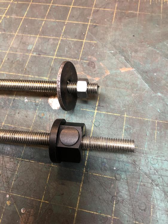
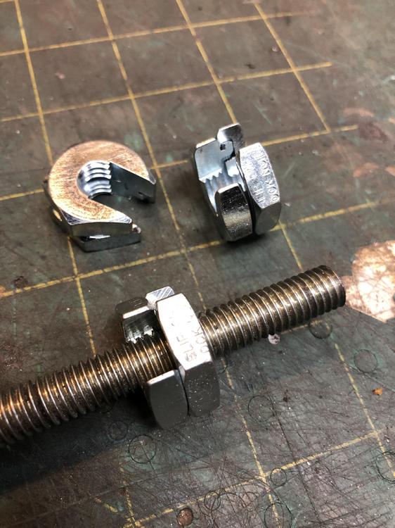
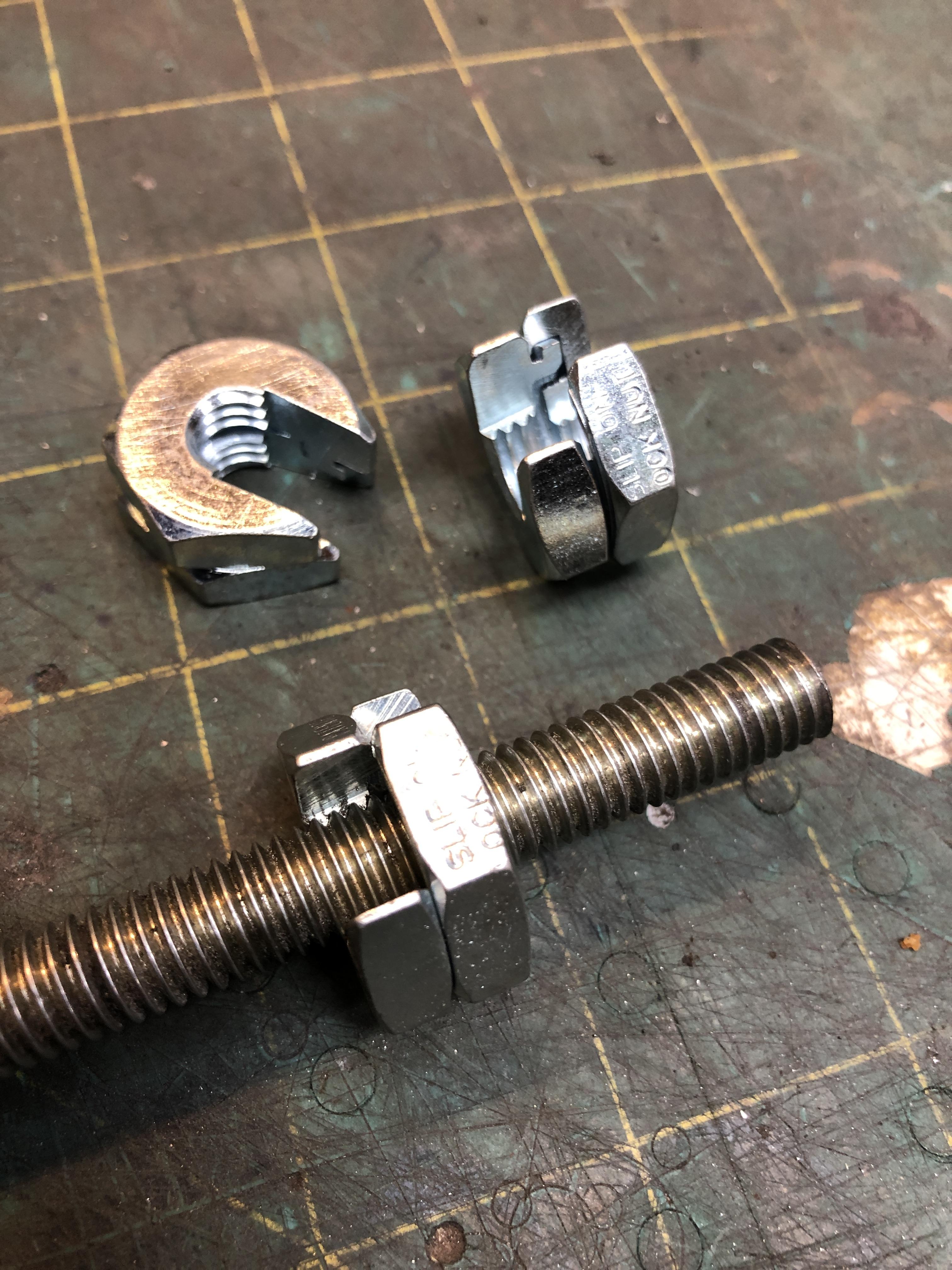
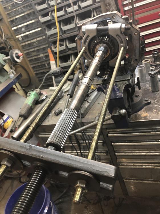
 I can't find Randalla's Floatsync product on ebay. Searched a ton of different ways. AK260's experience with his website being down is telling. I can't decide if it's fair to point people to a commercial source for the right size banjo fittings, I feel like I'd be doing Randalla a disservice, even though he is MIA at the moment. I found them with simple google searches. Once you know the thread dimensions of the float bowl plug, you will find them too. My initial design (not the one above that Site shows BTW) was to drill a hole in the drain plug, insert a brass tube in the hole so it sticks out 1/4", solder that in, then stick a piece of clear tubing on the end of tube and bend it upward. put a piece of stiff wire in the tube to keep it vertical. Then you have to plug the tube when you're not using it. I had spare plugs..... You all have to find the thread size yourself. I will not divulge my sources of the parts. Happy hunting.Does it have an aluminum rad by any chance?Ebay says the winning bid was $1100 Canadian. Excellent price! Did it sell locally or do you have to ship it? Good to have a local bench mark for 5 speed prices. Look forward to seeing more of your project. We have a Facebook group for Alberta Datsun owners. Calgary Classic Datsun Owners Group. Feel free to join up. Let me know if you need anything, we have a great bunch of Datsun nuts in your area.A buddy of mine with pets and a similar love of cars put me onto a great shop convenience and floor maintenance idea. Puppy Pads. Let's face it. If you have a Datsun, you have dribbles under your Datsun. If you take the engine out for example, you forget to cap the heater coolant pipes on the engine, and even though you drained the rad, when you tip the engine as it comes out, antifreeze hits the floor in great quantities. (I myself have never done this... I just imagine it's an issue). Puppy pad absorbent sheets are utterly fantastic. Big (30x23inch), cheap, super absorbent, did I mention cheap? 100 pads are $25 CAD at Costco. I used to use newspapers, but I no longer get a paper newspaper, so I've been scrounging for newsprint in dumpsters or begging from strangers at bus stops "Hey buddy, you done with that paper?" I did learn a few new words for "No!" however. Big enough to put under a transmission you happen to be rebuilding, under the engine when you're changing oil or draining the rad. Under me when I sitting on a dirty floor. Whatever! I even stuffed one under my big 60 gal air compressor when I open the drain valve to release condensed water. One pad holds a couple of quarts of water I swear. There. That's my "Hint's from Heloise" for today. Keep that floor clean!
 CO, yes, I see my jaws don't quite close perfectly, well one of them anyway. Grrrr... . I'm saying the run out is the lathe's fault. Still that one shaft with the pitting is trash or last resort use anyway. I took the trans apart (again) that has the missing 4th gear set and "borrowed" it's shaft while I wait for a donor to show up. Also found one of the sleeves that the needle bearings run on was pretty marked up, under 3rd gear. Switched that out for a better one from the above donor. Now maybe that tranny will make less noise. Got that seal switched around and buttoned up that trans, again..... I can do this with my eyes closed now. Wish I could post pictures.i took some pictures of a real S30 linkage and there are significant differences I think. I can’t seem to add pictures today for some reason, but I have doubts the Suzuki linkage is a bolt in. The most problematic issue is the angle of the wiper pivots at they pass through the triangular mounting plate. Hard to tell from the Dorman images, but their wiper pivots seems to be more or less 90 deg to the mounting plate, where both S30 pivots are definitely not 90, and they are each different. The little crank arm on the end that connects the free mounting plate is straight on the S30, but is clearly a Z bar shape on the Suzuki part. My hopes are sinking the more I look. Maybe there are useable components to use, but as a total bolt in replacement, I’m doubtful. I’m not tossing my selection of stock linkages just yet.Maybe he just spotted it and thought it looked way to similar not to work. He didn’t say anything else, just posted this link. https://shop.advanceautoparts.com/p/dorman-oe-solutions-windshield-wiper-transmission-602-885/10719361-p?product_channel=local&store=5412&adtype=pla&product_channel=local&store_code=5412&gclid=Cj0KCQiAtOjyBRC0ARIsAIpJyGNoSrTfthsi3VtZRBBZHq_Z2n6nFrwLhfcAjRg7g_llcr99PgGV0GwaApYtEALw_wcB&gclsrc=aw.dshttps://www.rockauto.com/en/parts/dorman,602885,wiper+linkage+/+transmission,8856 Harold Burroughs posted on FB yesterday about the availability of new aftermarket S30 wiper linkage from Dorman, PN 602-885. Just thought I’d spread the word. He reported the find from Advance Auto’s website, but Rock Auto has access to it also. Anyone with access to Dorman can get it. The price is impressive, $69 CAD. That’s about a $1.98 in USD, so who can resist? Yes as we know you can rebuild and re-lube the stock stuff, but if your shafts are all rusty (as all us old guys know), no amount of lubrication will make things go smoothly or last that much longer.Could it be any further away.....


Important Information
By using this site, you agree to our Privacy Policy and Guidelines. We have placed cookies on your device to help make this website better. You can adjust your cookie settings, otherwise we'll assume you're okay to continue.