zKars
Supporting Member
-
Joined
-
Last visited
Everything posted by zKars
-
I’m sure none of the 4 speeds reverse gears are interchangeable with the 5 speeds (B) and having looked at the reverse/5th gear setup in the C type 5 speeds (with admiration about how you can make it so complicated), I’m going to say with some certainty that they do not have compatible components either.
-
Options: 1. Get a a plastic 280z liner and use it. It just slips in, but needs some plastic surgery around the opening to fasten and fit it. Let me know if you want to try one. 2. Modify the 240z cardboard liner so it’s easier to remove. Slit the bottom in the center from the front to the rear, and do the same to the top or remove the top entirely. The top does nothing and you can’t see it’s absence when installed. Makes it easier to collapse it to get it in and out of the opening and to get the glove box light hooked up again. I add a new snug fitting bottom floor panel that slips in over the cut bottom to restore the structure and to make a nice looking interior. Get creative and cover it with velour/felt or vinyl to make it look classy. Lesser mortals will use a nice wide piece of dark Gorilla tape to re-join the cut section. Someone should come up with a new 3d printed plastic insert box that replaces the stock cardboard that slips right in and fits without modification. Could add a USB port, LED light, cappuccino maker, BT speaker, cat carrier grooming aid.
-
The remaining section length is 0.7” I believe. Let me go check a couple I have cut already. Better to be a bit short, you can add shims to push the alternator back and forth to position the pulley alignments
-
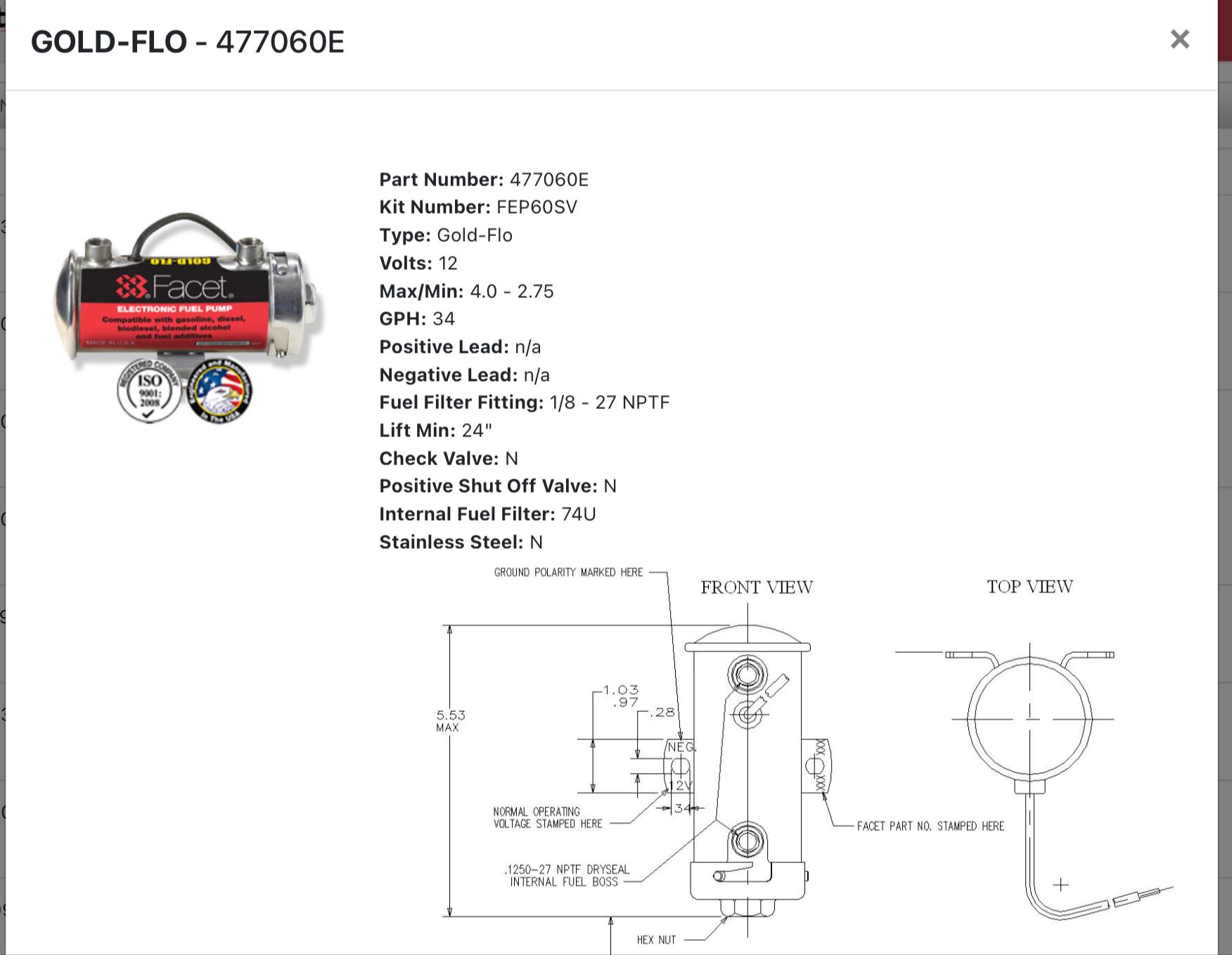
My goto electric pump is this one https://www.facet-purolator.com/gold-flo/

-
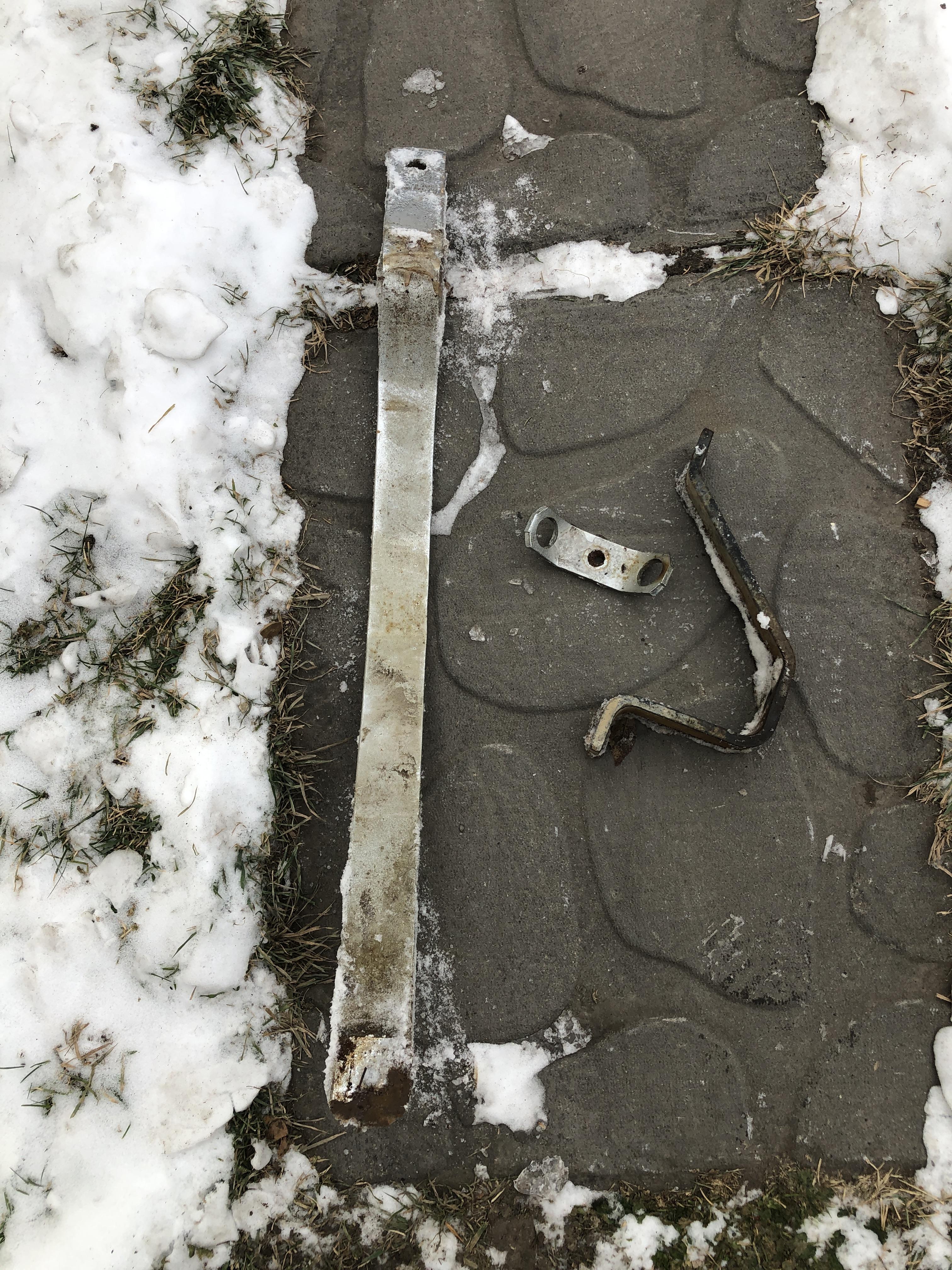
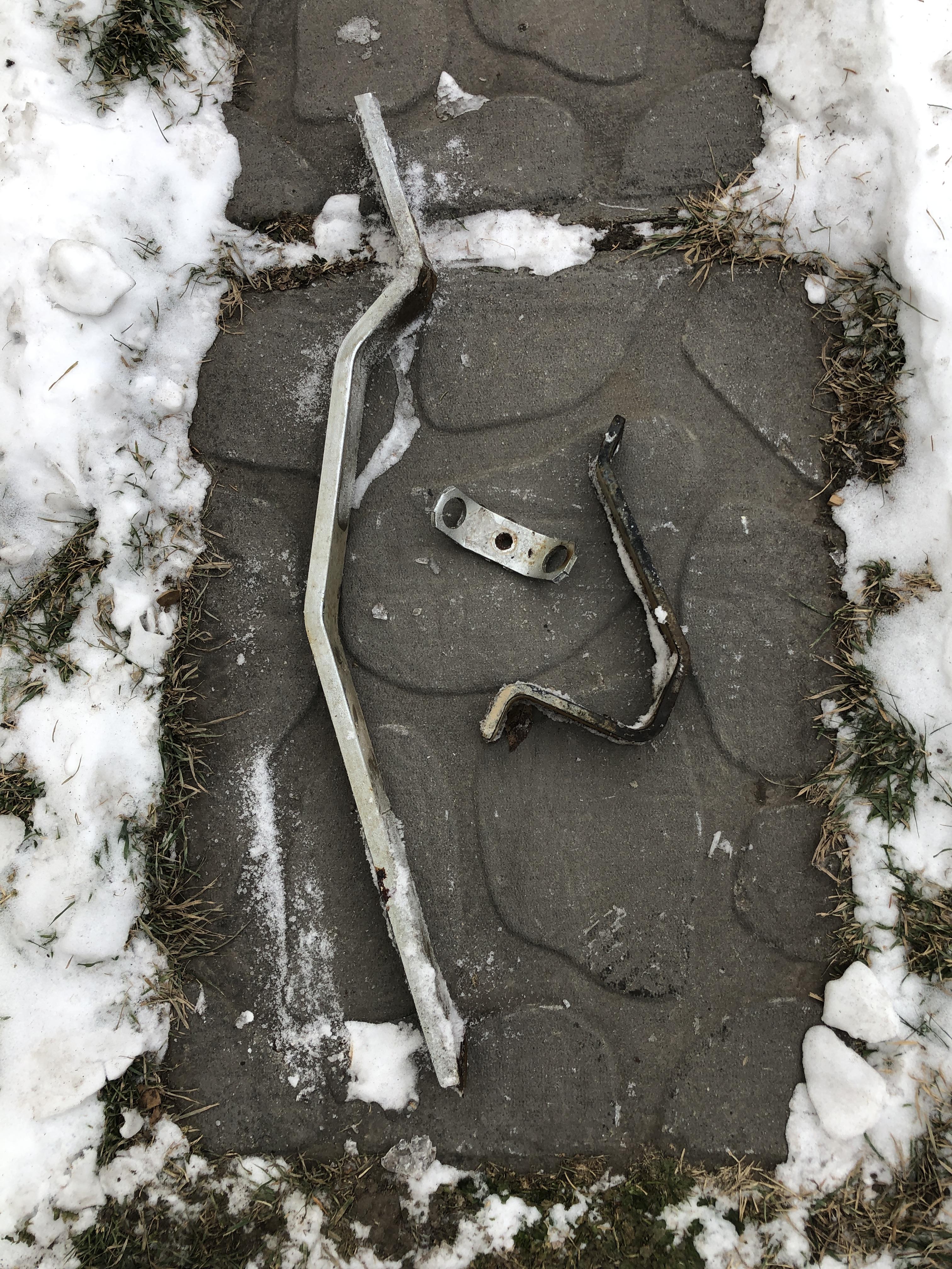
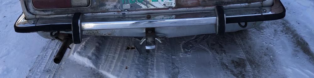
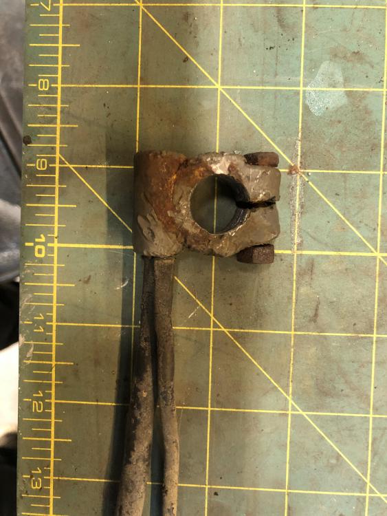
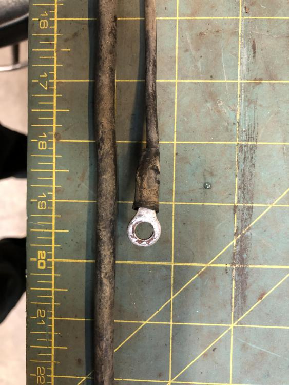
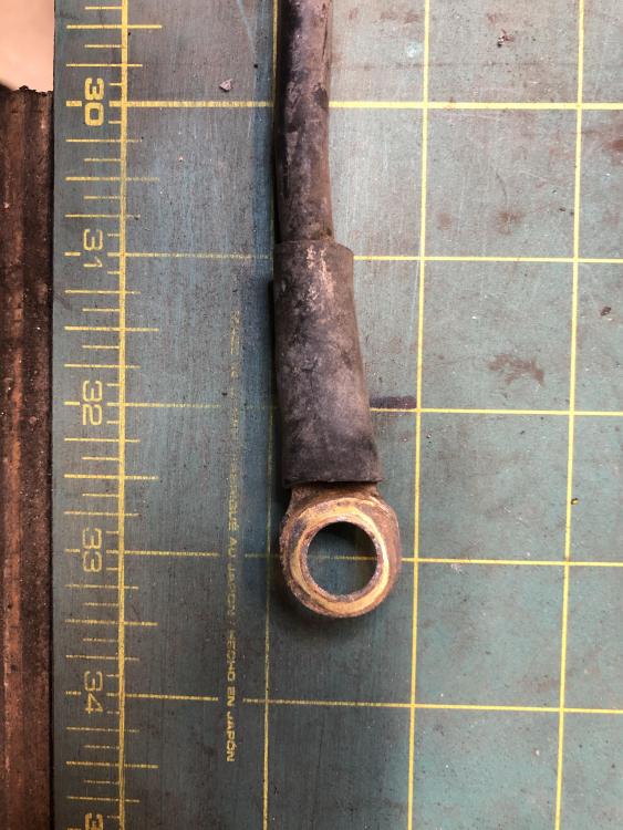
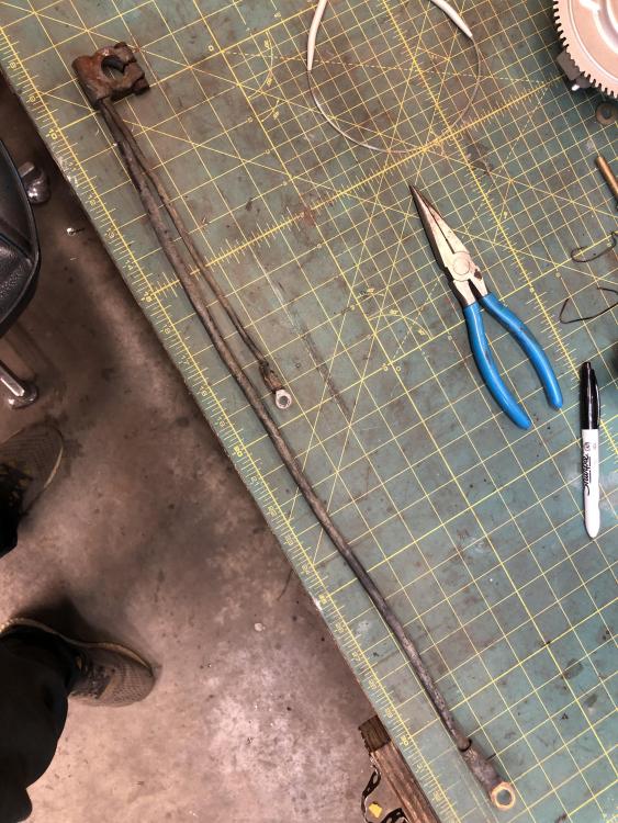
Here is what I have left of the towing bar I removed. If anyone really wants them, just ask. Bit heavy. Price of shipping.


-
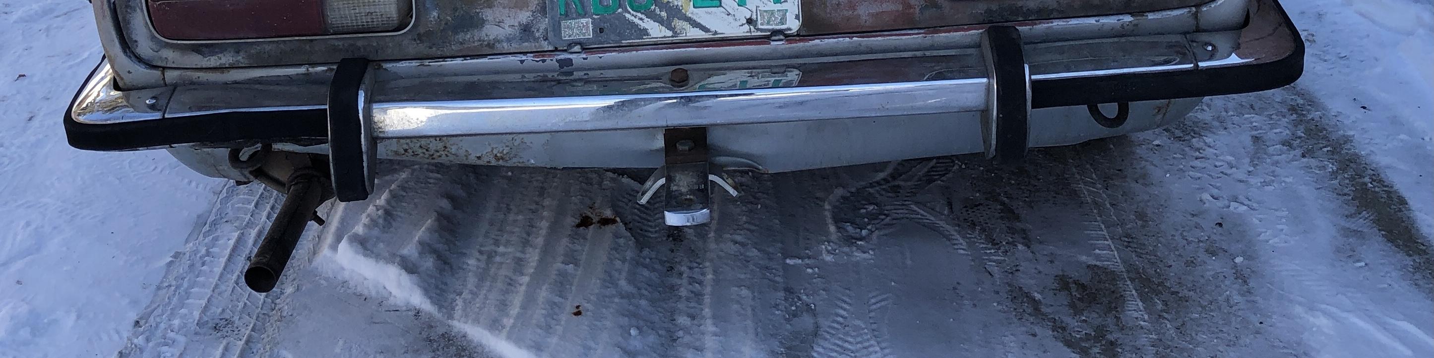
I just brought home a 71 Z that had a tow package attached. it consisted of a 3/4 x 3” thick tow bar that attached at two points. The front was bolted through the spare tire well via a cross bar and two 7/16” stove bolts, and the rear was hung from the rear bumper with a 5/16 bolt. Yup, nice long bolt, straight through. Ouch This is the only picture I have handy. You can’t see the big a$$ bar that runs under the spare tire well. It looks to be made for the car, the bar is bent in very specific places to fit tightly against the bottom. I have removed the bar from the car. It’s in the recycle bin at the moment.
-
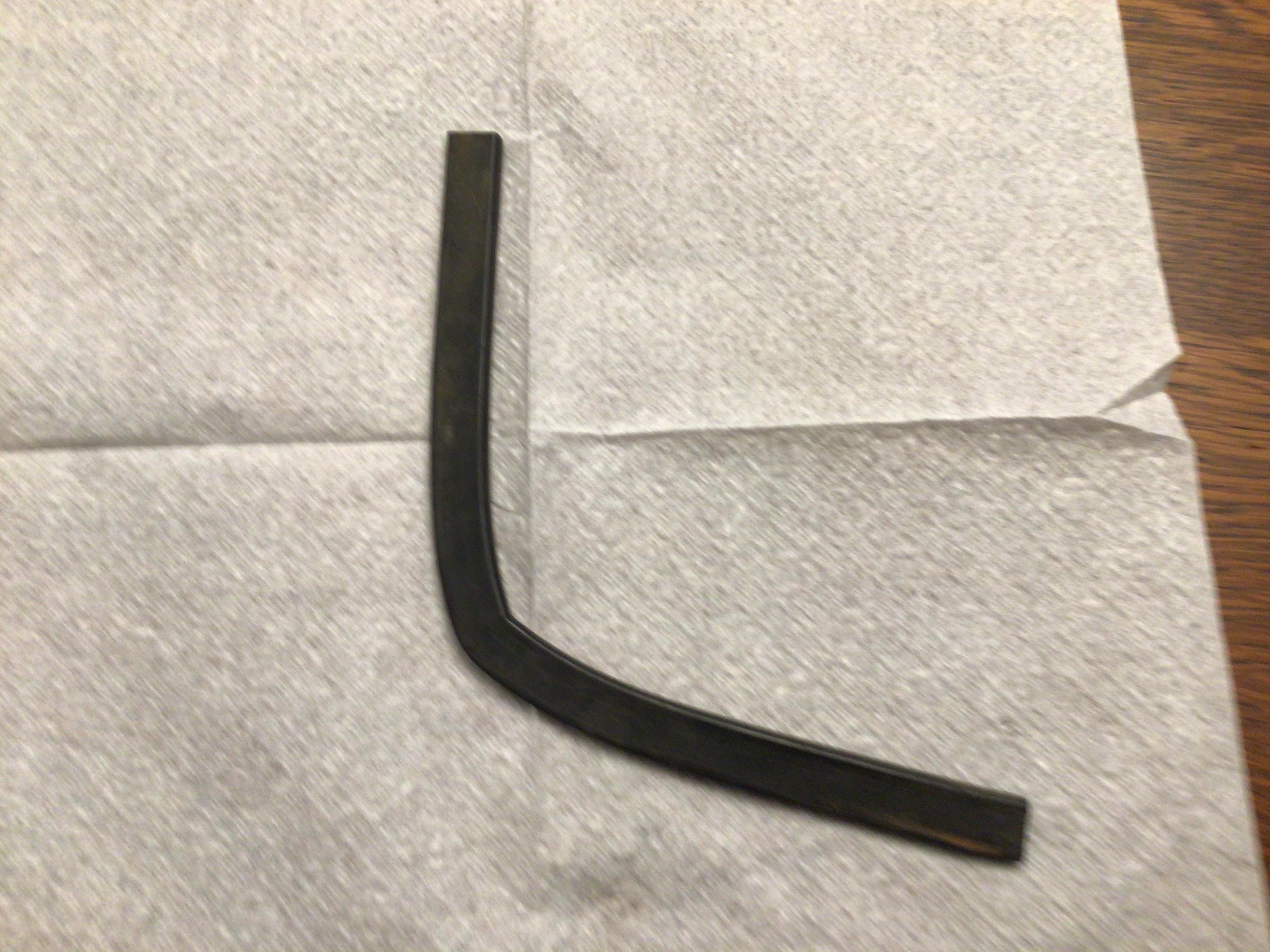
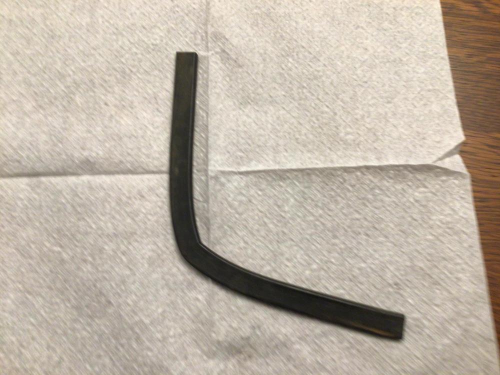
Look under “edge trim” on McMaster Carr’s site https://www.mcmaster.com/catalog/126/4052
-
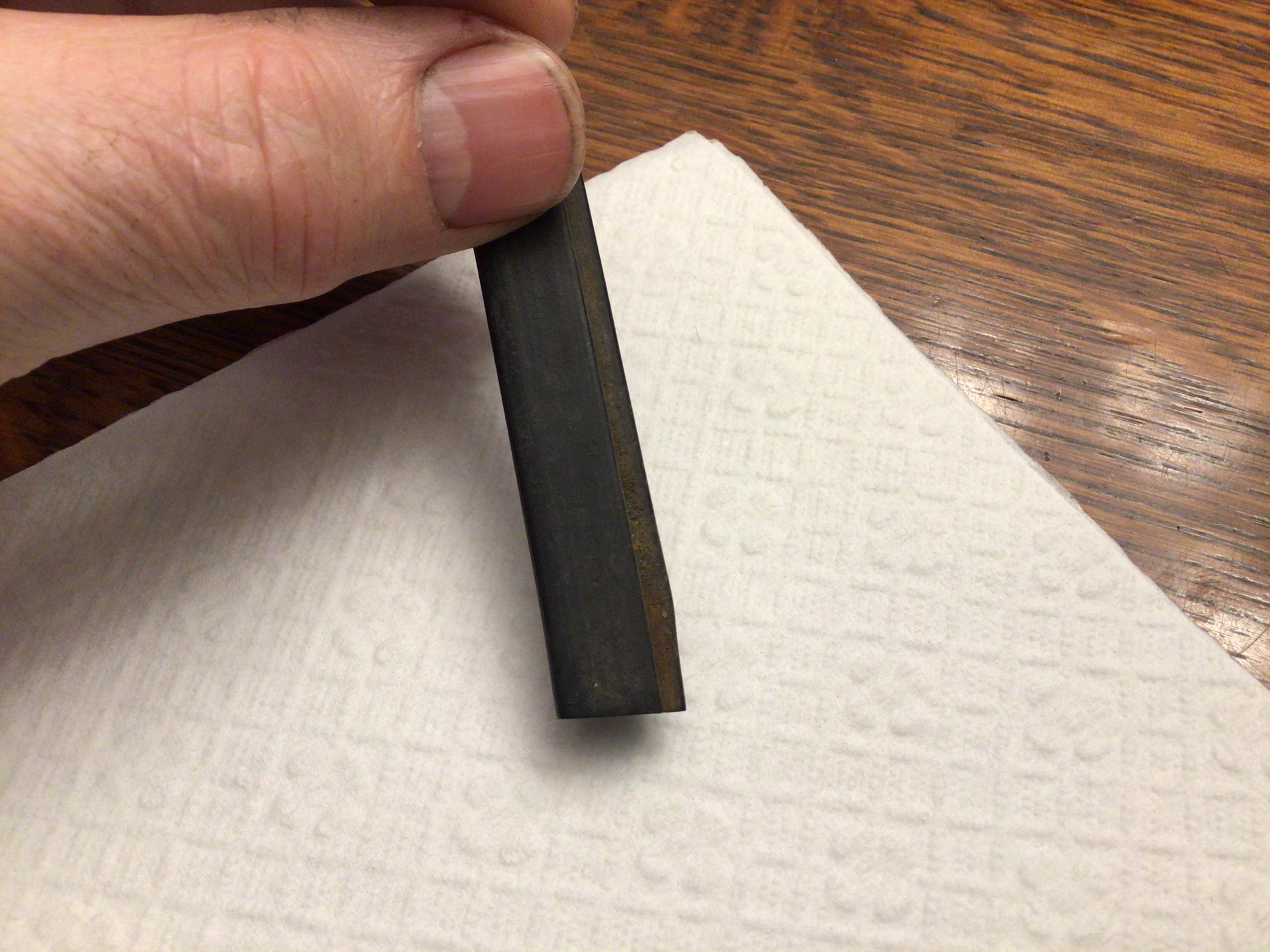
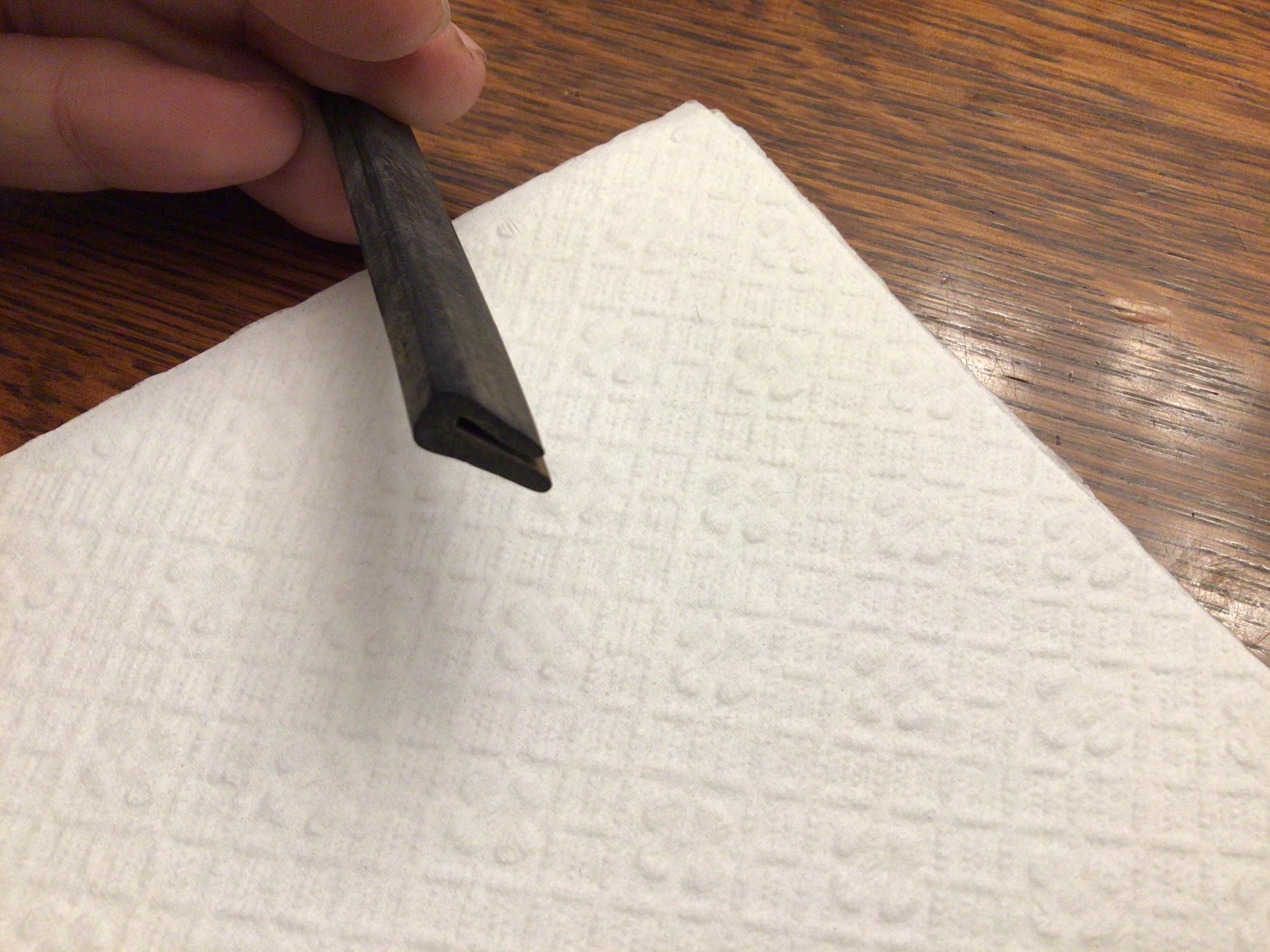
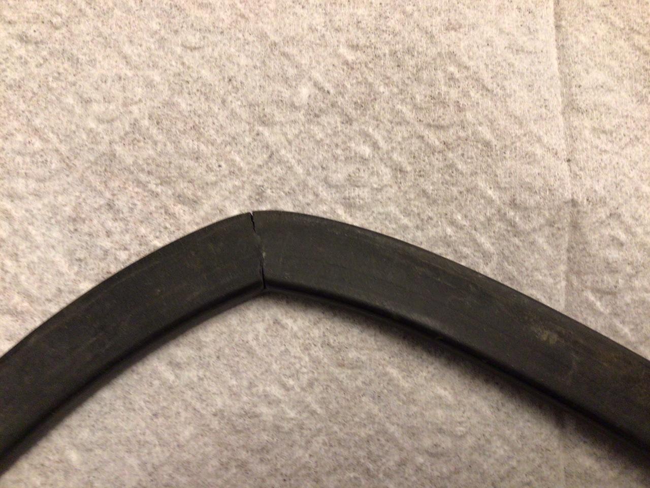
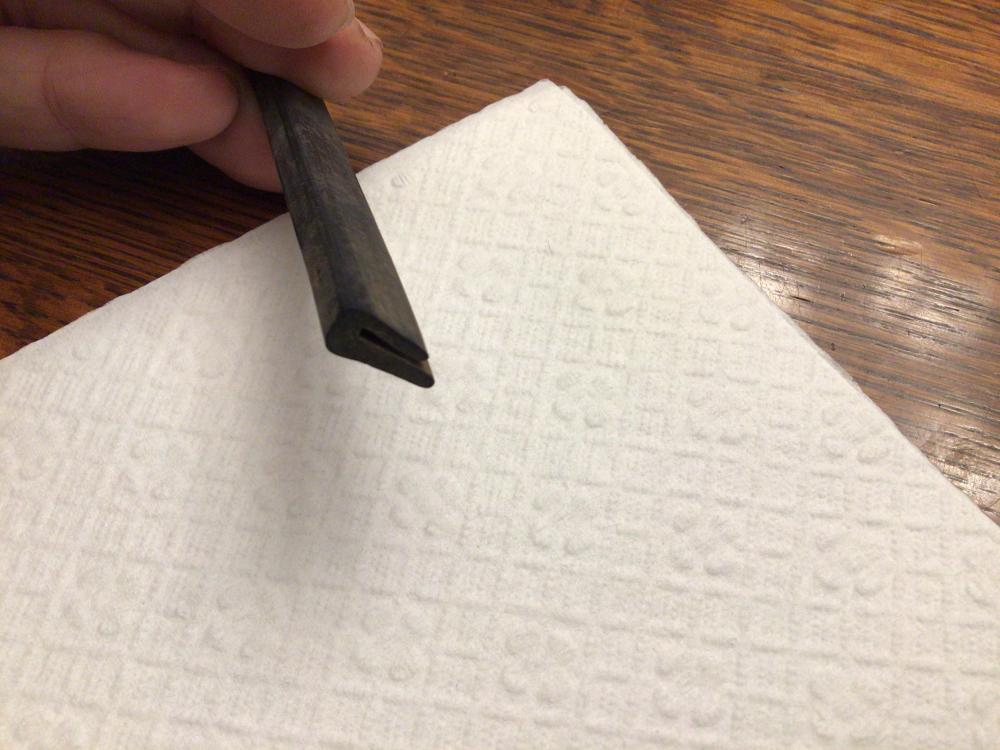
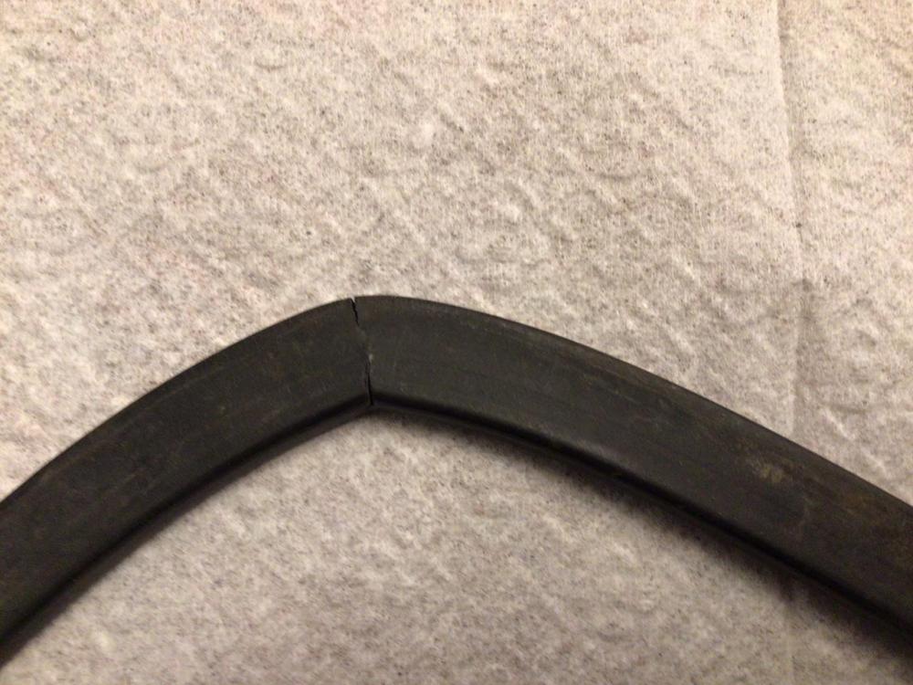
They are about 10 “ long, and 1/2” wide. The underside is a bit thinner than the top face. The slit is well under a 1/32 “ pretty close to a tight fit on the sheet metal. The bend is formed by cutting out a pie wedge and re-gluing or so it seems. There is a distinct cut there.

-
McMasterCarr has tons of stuff like that. Love that place. I wonder if I can find a piece and measure it for you.
-
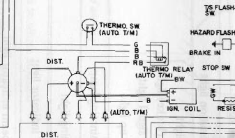
I believe it has to do with turning on the second set of points under certain conditions, for cars that have two sets of points, like auto's. BE-5 in the 72 FSM shows the relay doing this job, but not its location.
-
Heat it up, put it between two 3/4" sheets of plywood, then park your Z on it for a week. 😉 Time and temp will flatten it as well!
-
I also made my own. It’s called $1.00’s worth of rubber hose. There is nothing wrong with the OEM design except the strap is too loose or gets stretched with time and allows the diff to lift too far tearing the rubber in the isolator. Just add a rubber spacer to remove the slop. Yes I should zip tie the hose in place so it doesn’t work it’s way out. So $1.50

-
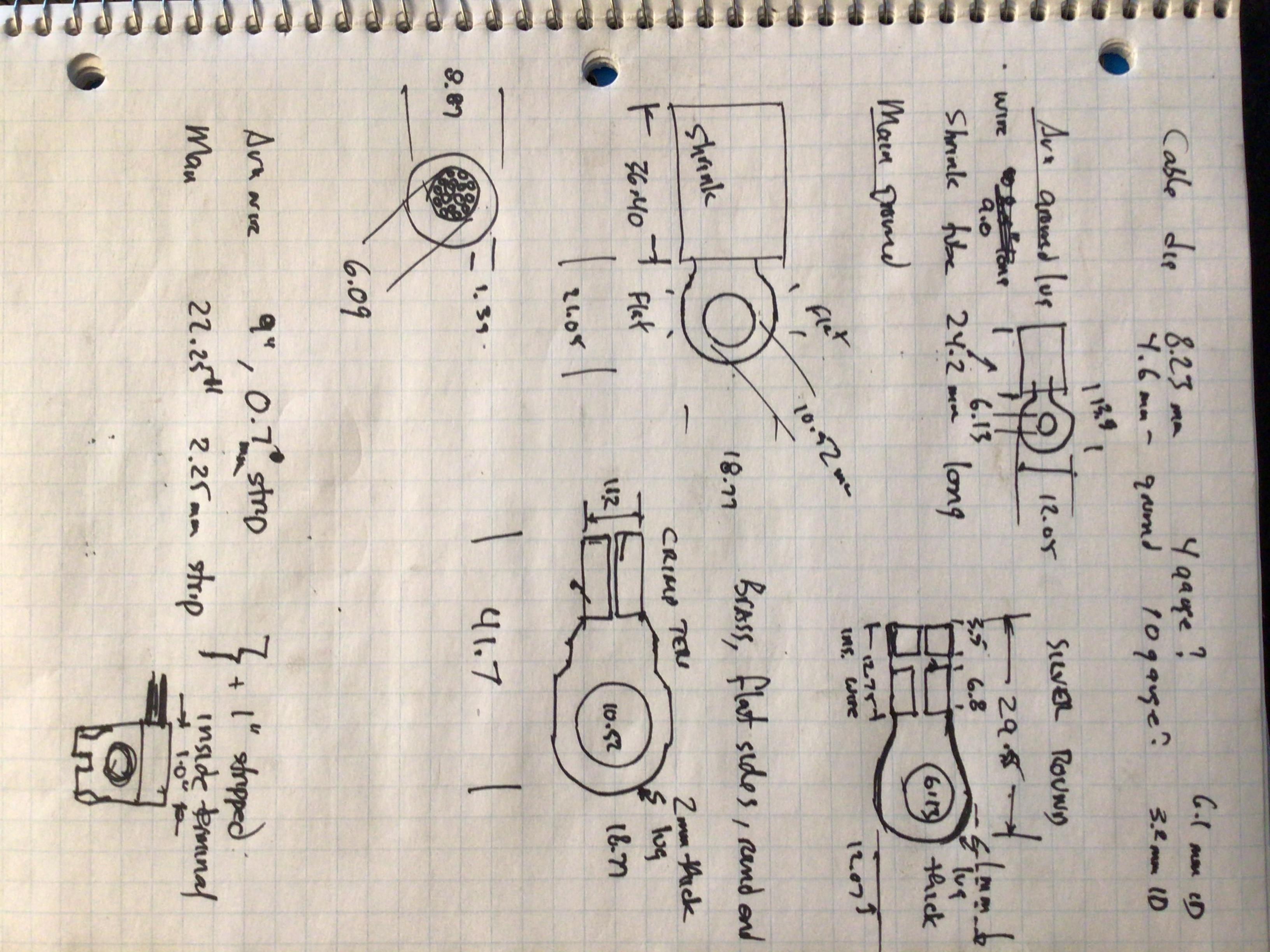
I really don’t want to get in the reproduction parts business, at least not yet. I do want to produce “reasonable” items that come close to the originals at first glance at a reasonable price for my own projects. I will include my rough notes and doodles of the detail measurements of my negative cable. Sorry for the not-perfectly readable scribbles. No I’m not a doctor.

-
Given the price, I’m kinda thinking they may be OEM cables. The Fiche does show different cables starting 72-07. Going to have to call them to get details if you want to see the difference I can imagine nothing location or lug size, or grounding difference. Might be a “better” battery terminal end upgrade or style or something
-
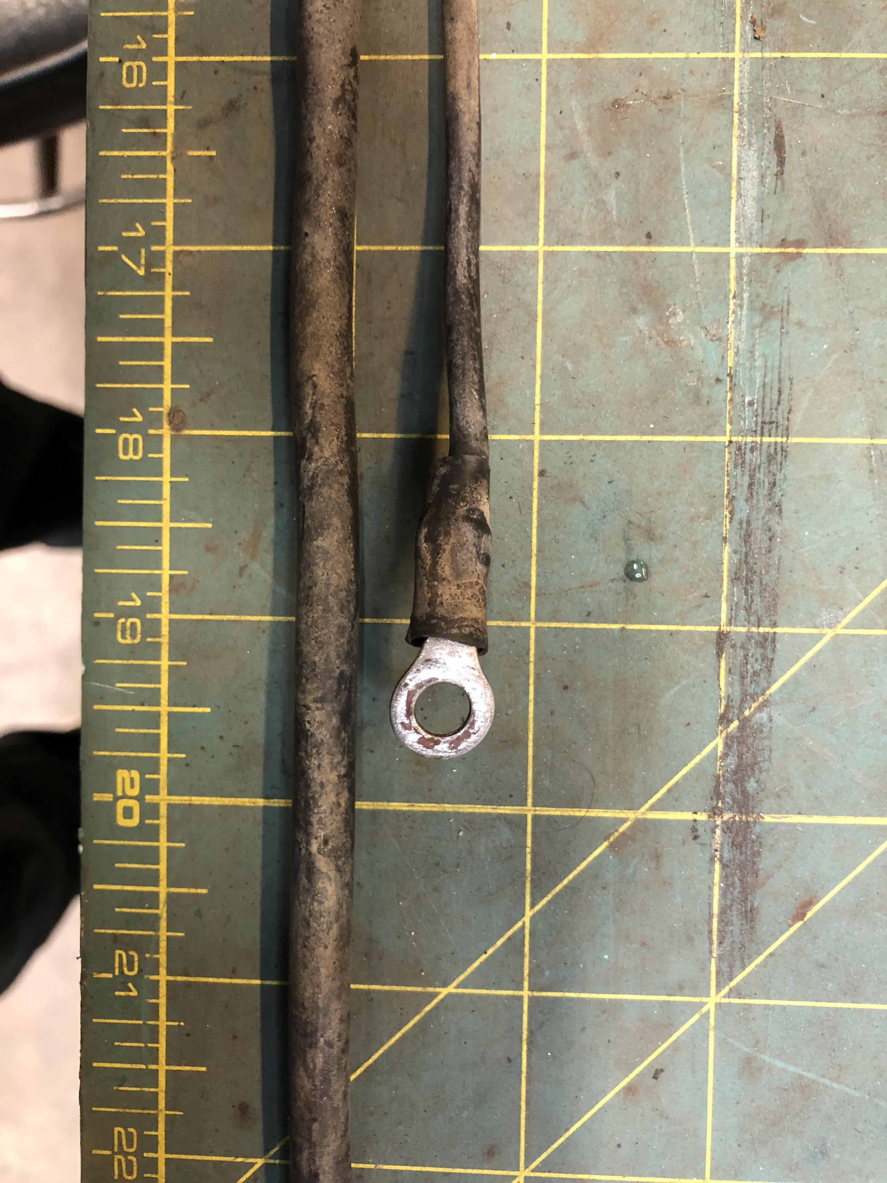
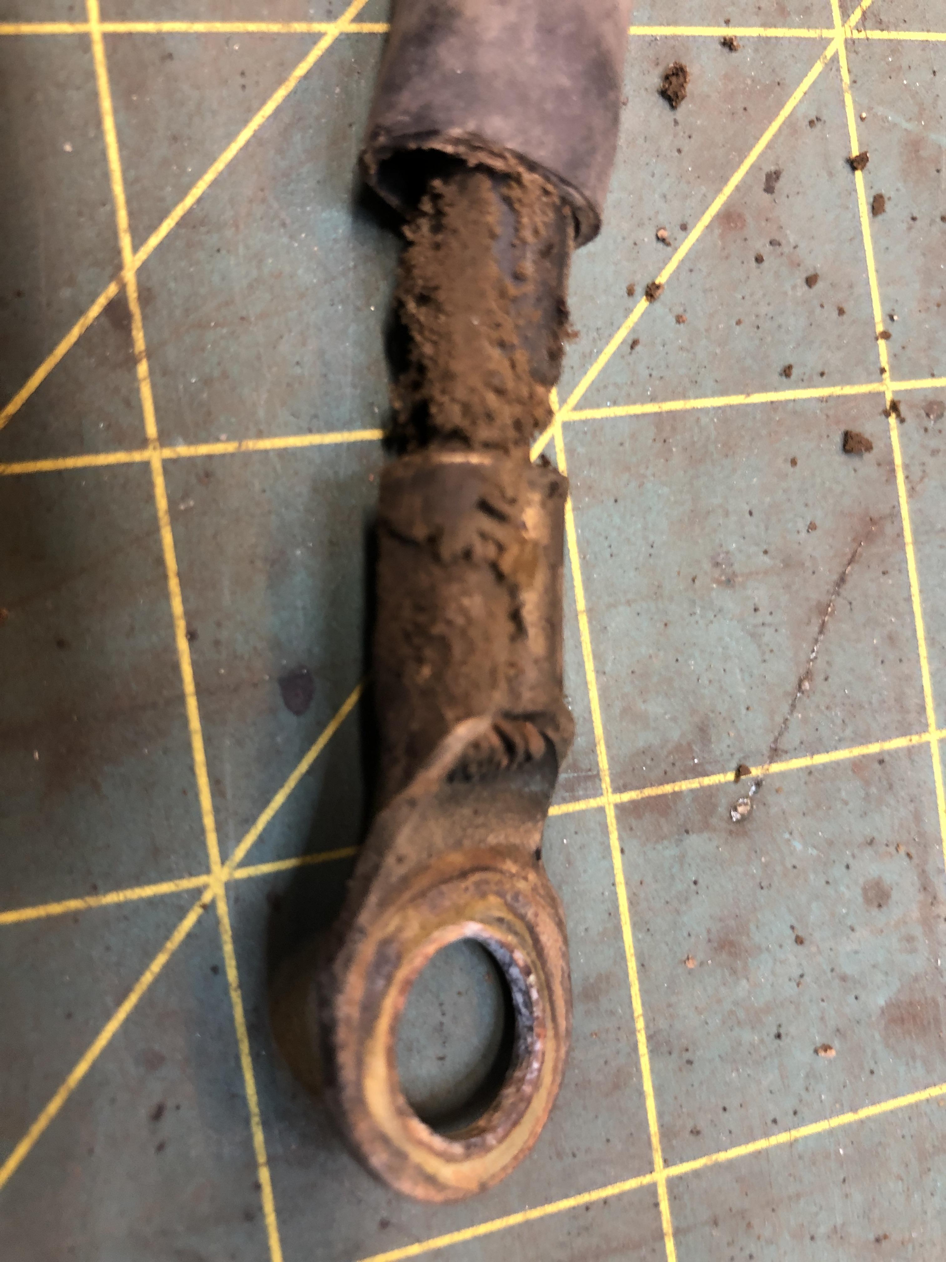
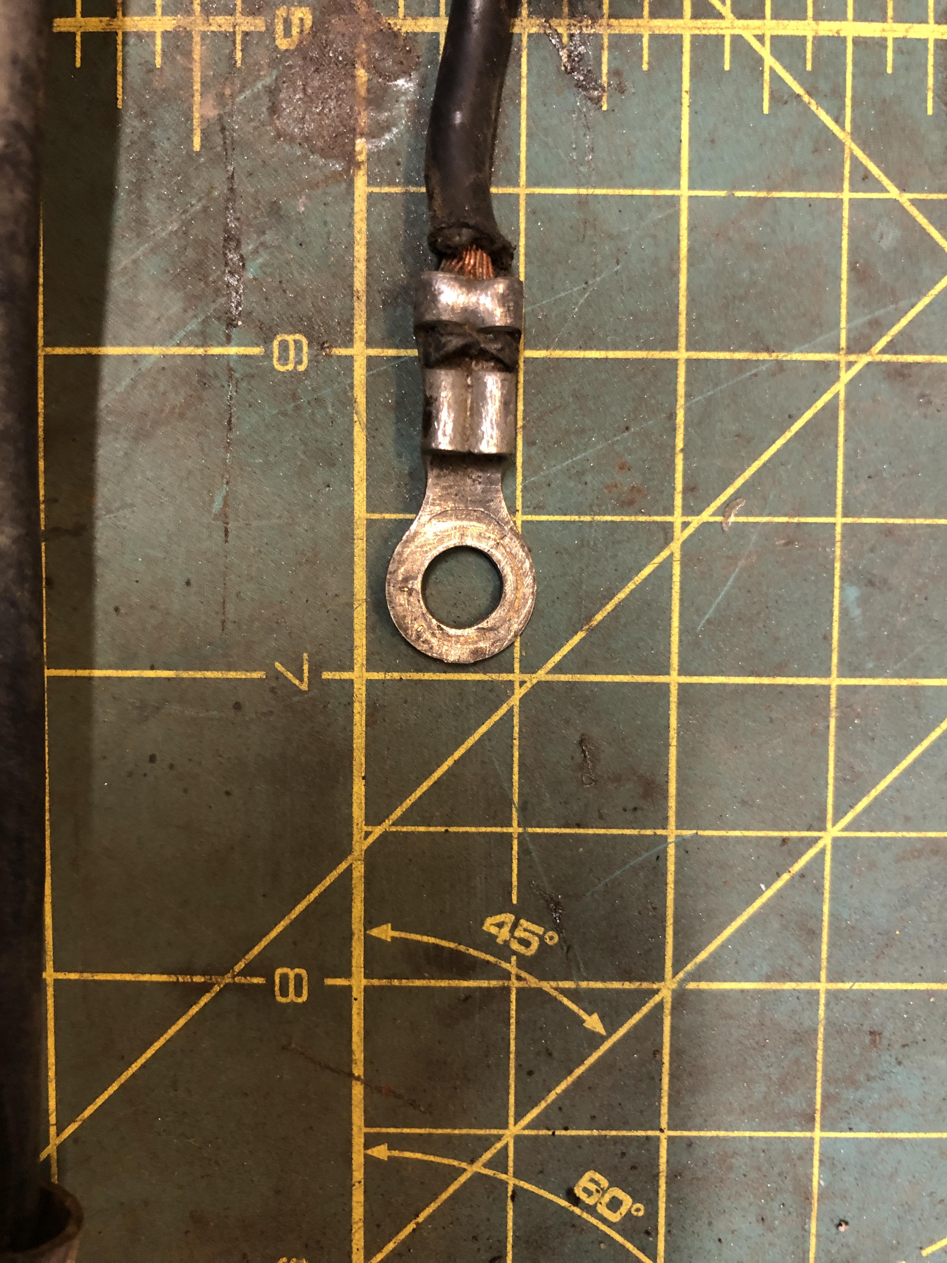
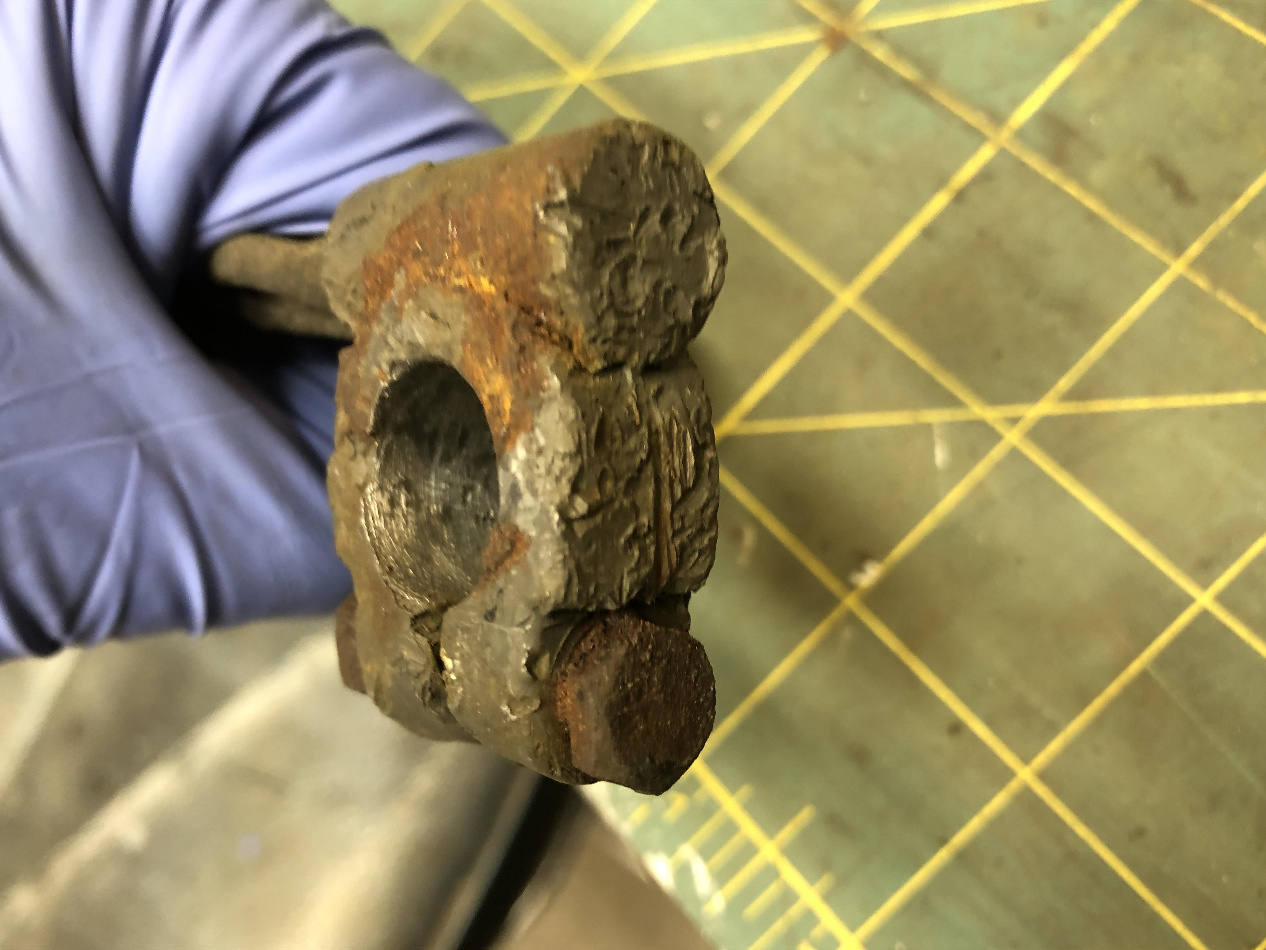
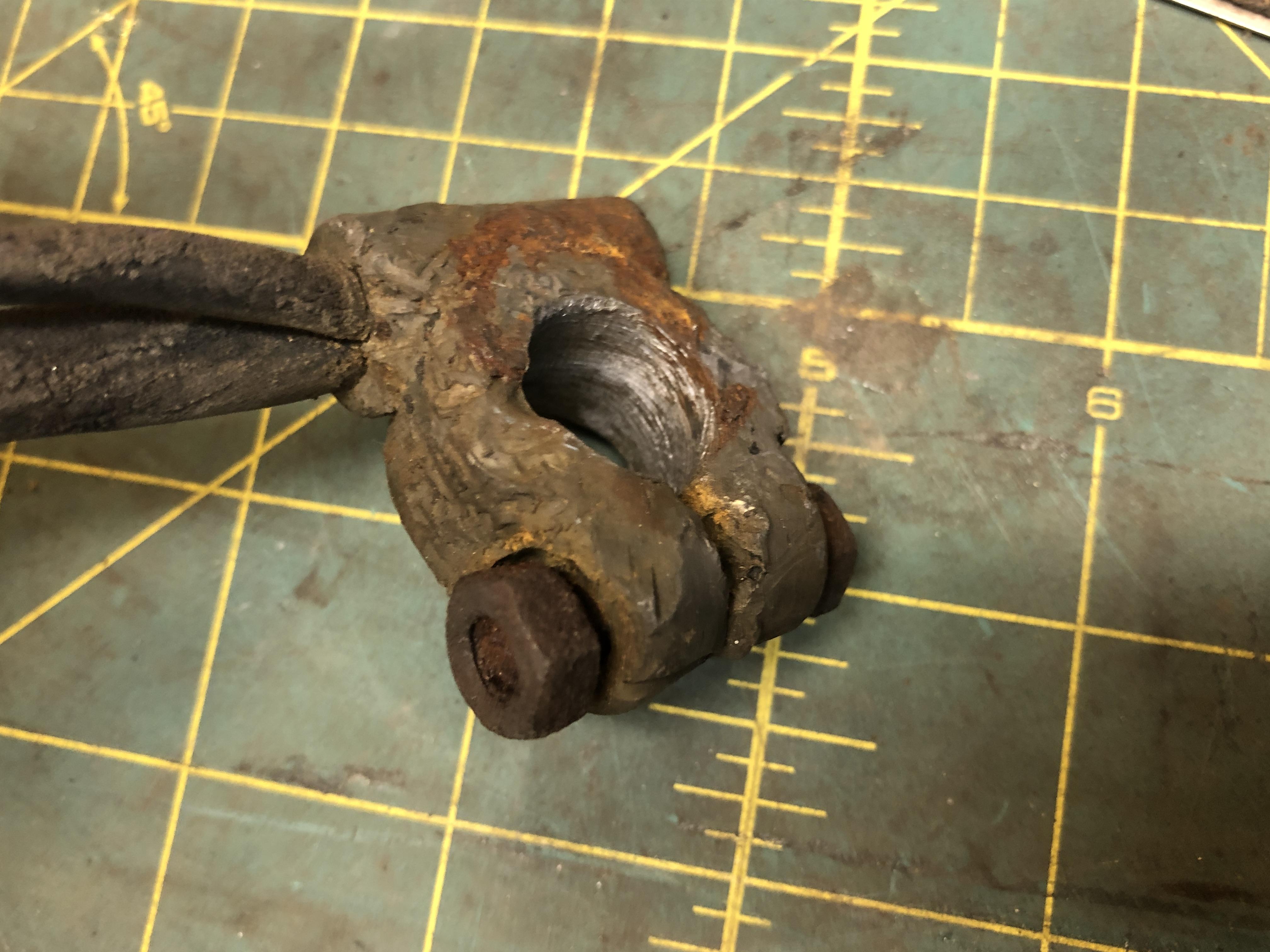
I realized I have one good original negative cable on the new to me 71 I just picked up. Now “we” need one of those original blobs to use to make reproduction blobs.... I’ve taken detailed measurements of the cable, lugs, wires etc. Finding the very heavy lugs that Nissan used is going to be a challenge in todays cheap crap marketplace. The big cable lug is a brass or copper monster made with 2mm thick metal and has a lovely crimped connection done with a serious tool.


-
Great ingenuity. Many of the Datsun family hood latches are very similar. There are hood latches, out there, you didn’t look in the right place. I have a few 240/260/280 hood latches that are replated real purdy that I’d part with, but it seems you have your solution right there. Nice work
-
Nothing like more options. https://www.aircraftspruce.ca/catalog/pnpages/15-04818.php?gclid=CjwKCAiA17P9BRB2EiwAMvwNyGDVuhht0dypa-XwCNqz7pVIJ_WSV9hDGVqKnMOl-WcpRjx2K9uCiRoCFJUQAvD_BwE Gotta trust an air craft supplier would sell hose that is fuel worthy. Been studying fuel tubing. Seems Viton tubing is getting the nod. One description. https://www.new-line.com/hose/tubing/viton-tubing/viton-rubber-tubing

-
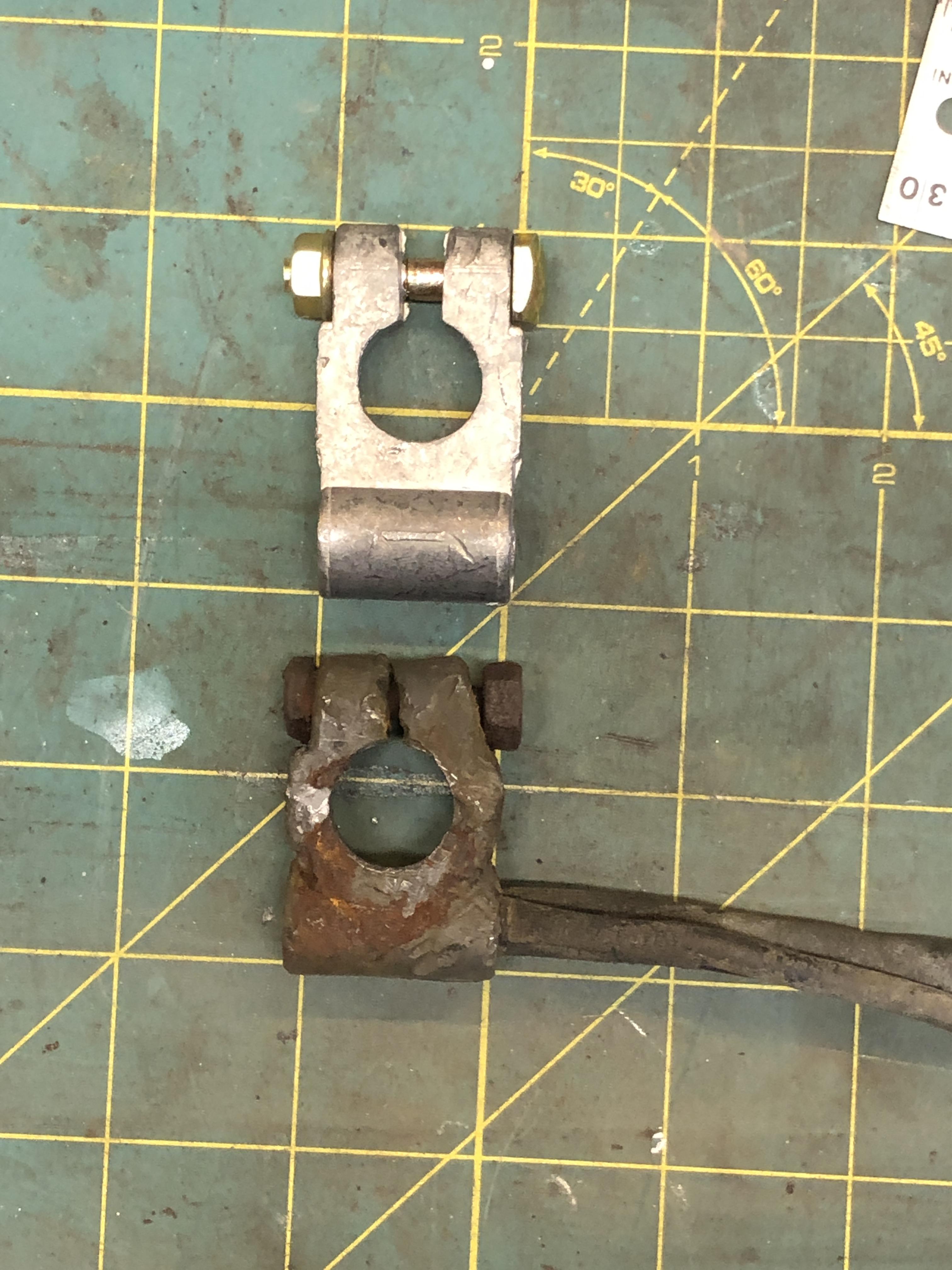
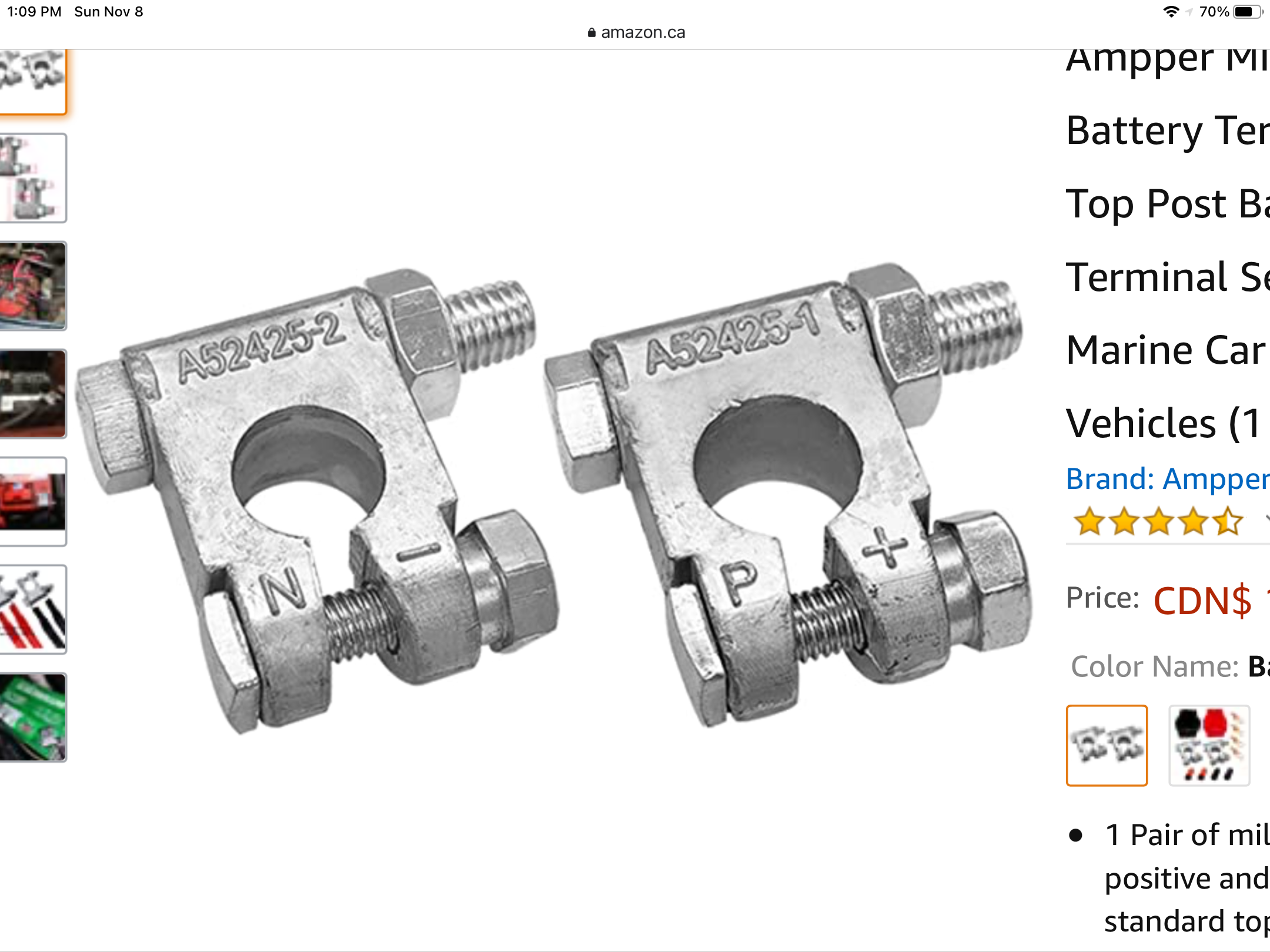
Finally dawned on me what that black blob is on the positive cable. It a rubber cover for the terminal. Now I have find some that fit the terminals I bought to do this right(er).
-
That site has the positive one as well.
-
Some info and pictures here.
-
I’ve seen kinks and I’ve seen hoses that are so stiff they impede choke motion. OEM stuff is amazing, the 40 year since last started last Z I’ve been playing with, still had soft hoses I’ve been using the silicon tubing that RC hobby stores sell for the nitrous fuel they use in RC car and airplane engines. Comes in different colors too! Pink is nice. No doubt Z Therapy has some input on this Wait I’m Canadian, COLOURS.
-
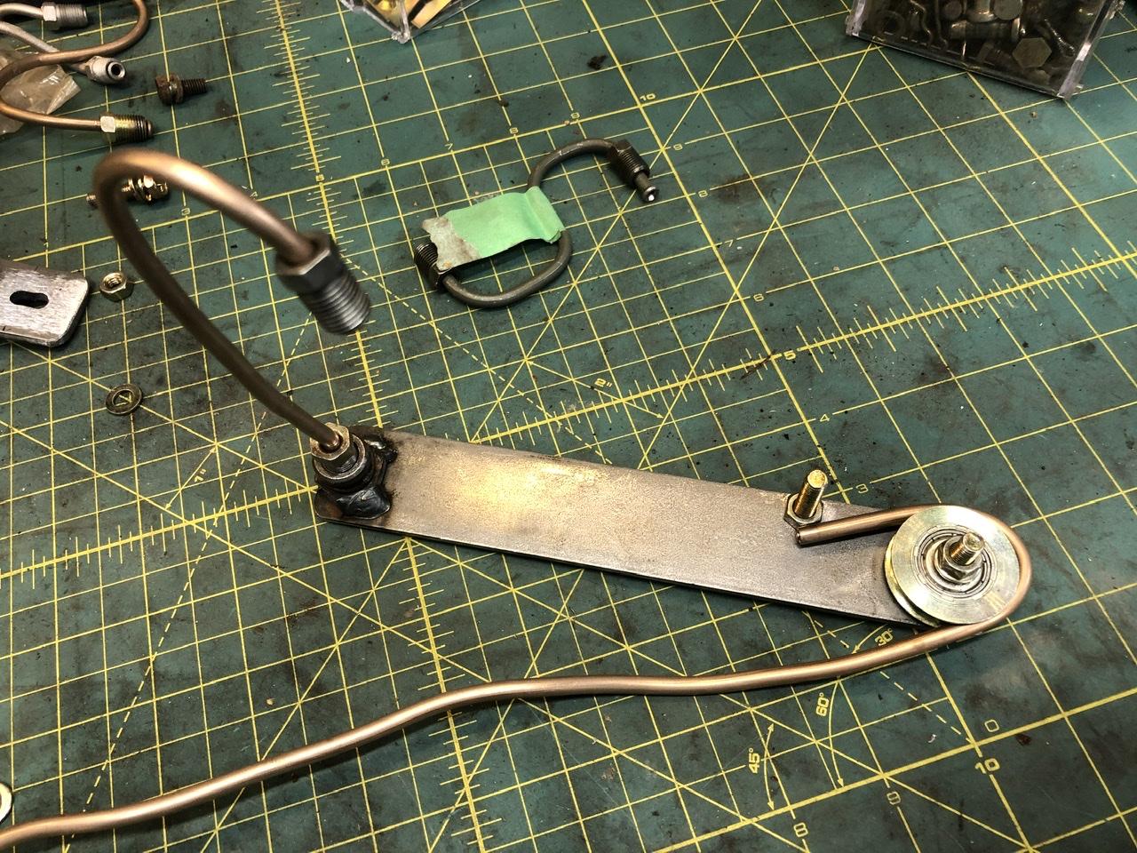
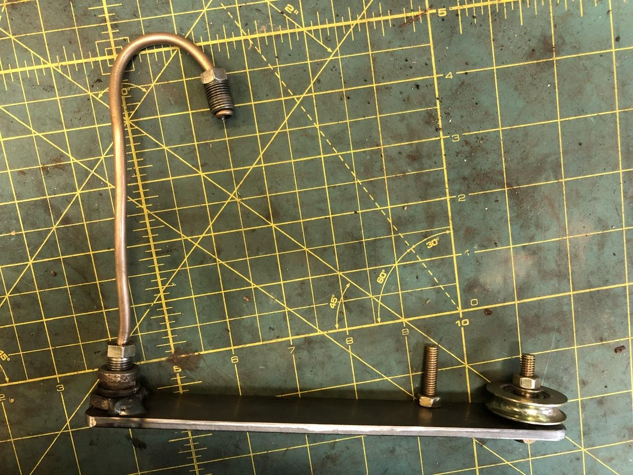
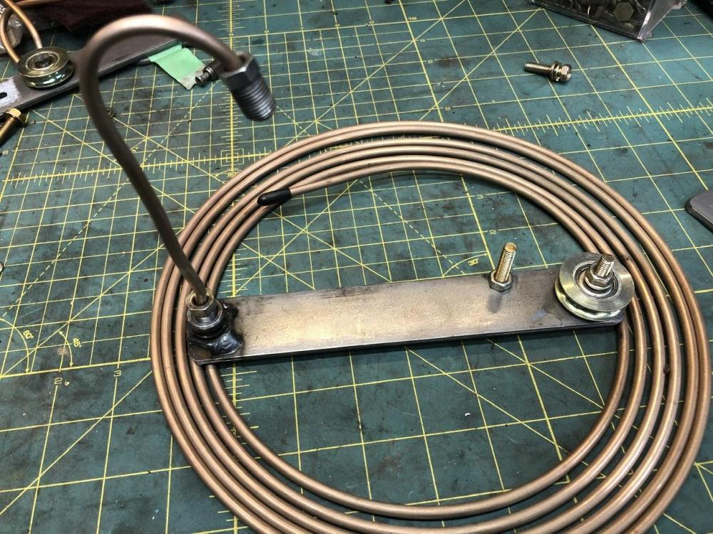
Yes there is a 1.25 diameter roller thing at the other end to help you form tubing as well if and when that comes in handy. That wheel is a screen door bottom guide roller. It has a 1/4” groove, bit bigger than the 3/16 tubing, but works just fine.

-
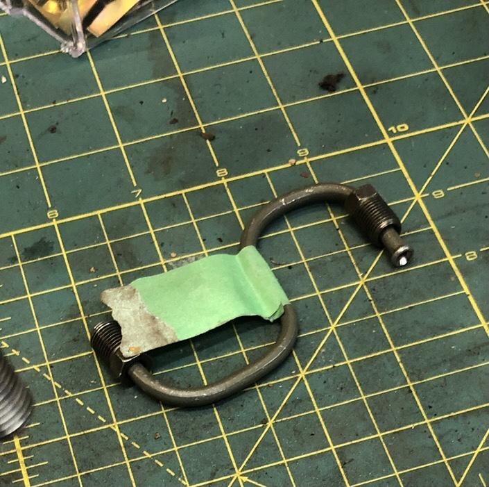
Just stare at that little beauty for a minute. The brake line threaded into that little remnant of an old brake line welded to the bar is the secret weapon. I already use the CuNi tubing and have for years. It is very soft and forms nicely in my powerful hands. However, there is one bend type that is always challenging and of course occurs frequently. A tight curve near the end of the tube. Bending the end of the tube requires more force as the leverage is reduced with shorter length. Don’t believe me, make a 180 in the middle of a 12 long piece, then make it again at the end. My finger tips cringe at the thought of it. Dang, if only there was a way to safely, easily grab the end of the tube in a vise grip or something without screwing up the threads or crushing the tubing and giving me an extension handle to increase leverage. BINGO! Thread the tube nut into an old female brake fitting welded to the end of a scrap. Consider that little devil tight S curve on the stock front caliper. TWO tight 180 bends near BOTH ends! Impossible to make it nice and pretty and kink free! Not any more. I made a bunch. Need any? All of these were created on the car on real stock calipers and strut tube mounted hose ends, so they fit perfectly. They are R and L sided. They took literally 5 minutes each to bend and fit. Yes, they are not the exact same shape as the stock ones, sorry. Those bends are ridiculous.

-
Cool tool of the day for November 8th. Been making brake lines again on the latest project, and finally made that little tool that makes some of the tighter bends really easy.

-
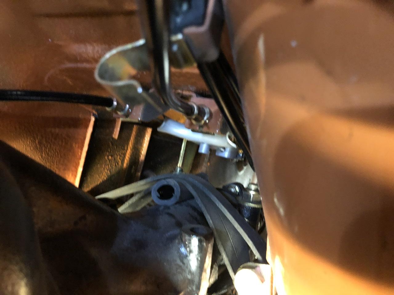
I’m digging that engine bay. Share with us your source of battery terminal/cables please. Quite tough to find that style already made up, or are you putting your own cables into empty lead terminals. Closest I found were these. I suppose one could solder cable ends into the hole where that boilt passes through?