


Leaderboard
-
Captain Obvious
Community Member1Points10,150Posts -

Zed Head
Community Member1Points19,555Posts


Popular Content
Showing content with the highest reputation on 08/02/2025 in all areas
-
1 pointIt might be fun to run with the ECU cover off. When you kick the case all of the components feel it. With the cover off you can pick the one you want to test. Hit it with a hammer, wiggle it, whatever. It is odd though that two ECU's would have identical failure characteristics. Might be worth the tme to do a pin drag test on the active pins in the connector that CO shows in his diagram. Maybe you have a loose one.1 point
-
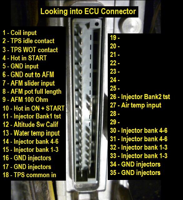
1 pointThe input filters could certainly become intermittent if vibration has taken it's toll. You could put meter across the visible wire coming off one side of the input choke coil and it's corresponding ECU connector pin. Should be pretty easy to figure out which pins they are filtering. Many of them are dead shorted, but the few (three?) that have the coil installed should be easy to determine. Looking at the approximate positions of the filters on the board and the pin functions of the ECU I/O connector, I'd guess that the filters are on pins 7, 27, and 13. Those would be inputs to the ECU that would be susceptible to noise. Those pins are 7) the AFM slider, 27) the air temp input, and 13) the water temp input signals respectively. But of course, that's a guess from across the interwebs. Here's a crude sketch I whipped up bunch of years ago. I know this info is available in other forms, but this form made sense to my brain: So about the failure mode for the Darlington outputs... No, they would probably not fail in the mode you are seeing. HOWEVER, the solder joints TO those transistors could fail with the symptoms you are describing. Any solder joint on the board could potentially go intermittent over time, but it would be unlikely for most of them. Vibration, stress, and temperature would be the risk factors. So about those risk factors... The reason those output transistors are so big and bolted firm to the chassis is that they get hot. There's your heat risk factor. And the I/O connector gets mechanically stressed every time you move the wiring harness or attach/detach the harness to the ECU. There's your stress factor there. Bottom line... If I were looking for a failing solder joint, I would start at the I/O connector and the output transistors. However, all that said, if I'm placing a bet at window #3, I'm betting the root problem is not inside the ECU case.
 1 point