Leaderboard
 Subscriber


Popular Content
Showing content with the highest reputation on 11/15/2022 in Posts
-
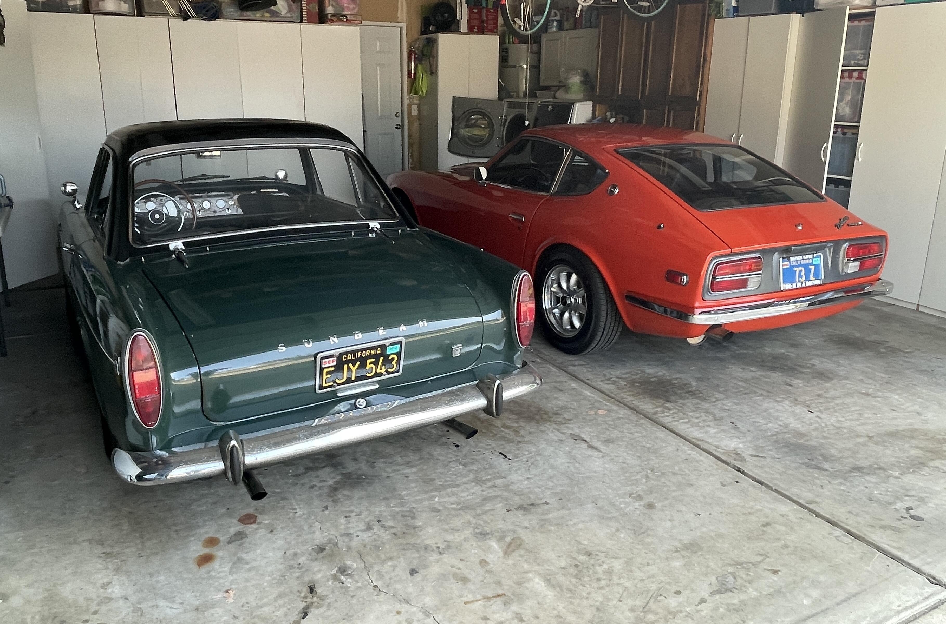
Just posting as a curiosity... Looking to try and find out whatever happened to my old '71 Z. She was sold to a fellow club member (Newt Zane of ZSport of San Antonio) back in 2008: VIN #18684. He used to stop by the house every once in awhile to allow me some "visitation'! I've since lost track of him and was just wondering where she might have ended up at. She and I spent 15 years together, 8 of those years being a very long & slow restoration process. It's like losing contact with one of your kids and you just want to make sure that they're alright.2 points
-
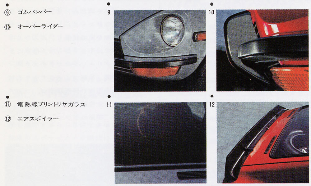
2 pointsSo, the cars without bumperettes are mere base models when compared to the more upscale well optioned models. 🤣2 points
-
2 pointsOverriders were an extra cost showroom option on Japanese market variants. They were listed in the sales brochures and in the factory parts lists.
 2 points
 -
1 pointBack in the day when I restored my Series 1 (I agree with others here, you have a S1 console), I used SEM Black in Satin finish for the respray on my console and other interior bits. The finish was near spot-on. The SEM product line for plastic has an Activator that is sprayed on before the color. It ended up very durable. I've heard good things about the DupliColor line for plastic paint, but I've never used it. I have used the SEM product line on multiple vehicles and multiple colors. Top of the line product in my book.1 point
-
Thank you HS30-H for putting it in the plainest of terms. He worked the Mustang crowd and then Volvo owners. Now he's concentrating his efforts in our direction. However, my spies tell me he has branched out into wooden speed boats! The first time I spoke out about him, after hearing my first 240 Guild horror story directly from one of his "marks" I got a thinly veiled threatening phone message upon arriving at my shop one morning. One can see how effective his threat was. I invite any interested parties to Google Robert Jackson Madill, OK for the full story.1 point
-
1 pointDo you have everything connected as it will be when the car is finished, including all grounds? It is possible that the system is back feeding if parts of it aren’t fully connected and grounded.1 point
-
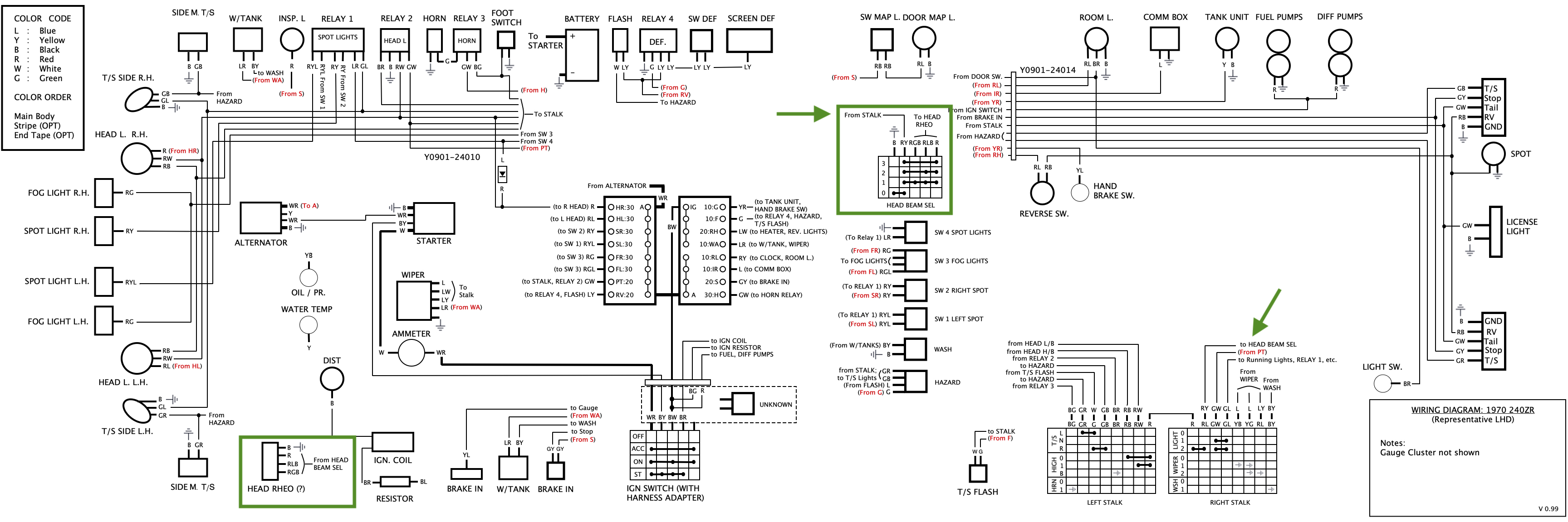
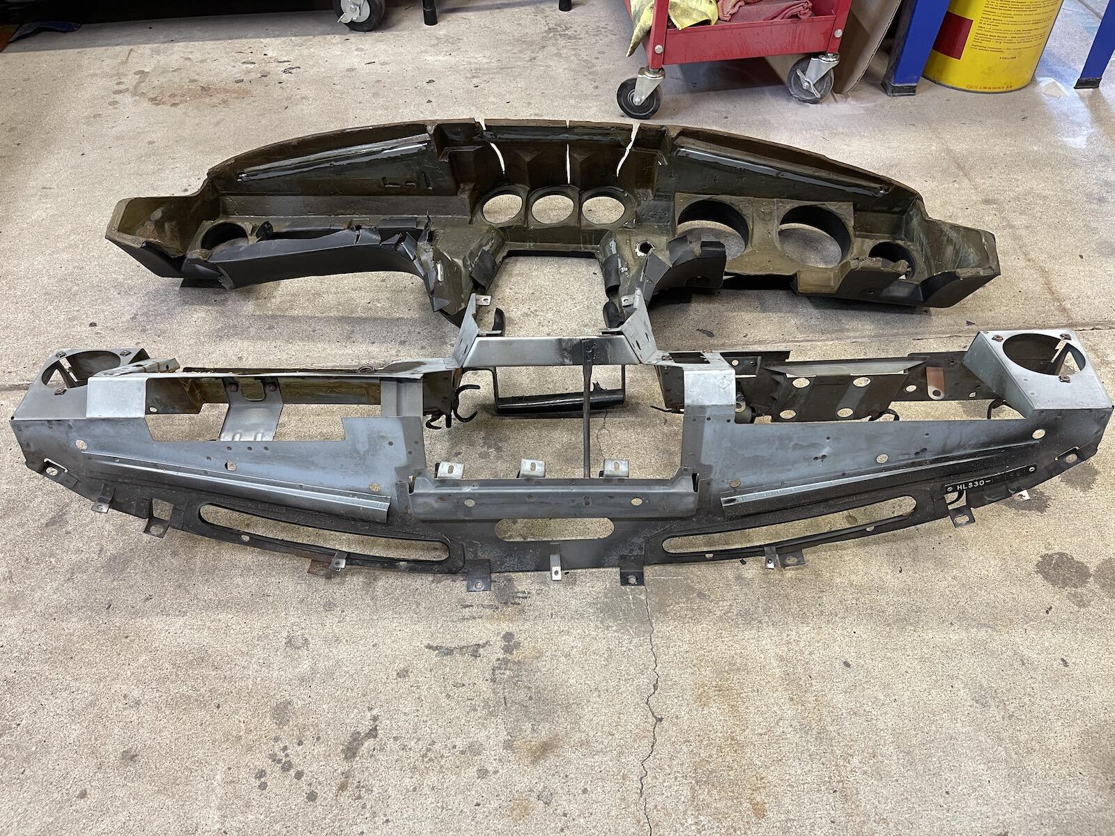
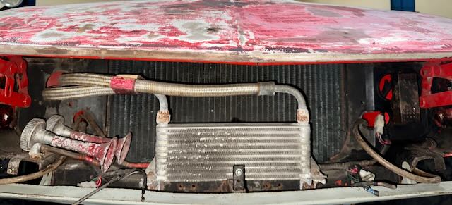
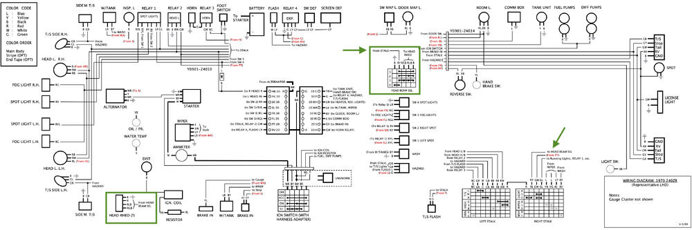
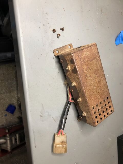
Today's upload shows a view from the front of the car. On the right side of the car is the FIAMM air horn assembly. To my eye, this (plus the accompanying compressor) appears to be a basic unit, most frequently seen on a period Ferrari. Just based on pictures I've seen of other Works cars, there doesn't appear to be a standard compressor unit that Nissan incorporated, and the horn location appeared to vary from car to car. It's actuated via the standard horn pad on the steering wheel, and alternatively through a foot button on the passenger-side floor, akin to how a windscreen washer fluid button would be placed on an old car. Also shown are the oil cooler, fog light electrics, and hot air tubing, which runs from the headlight buckets to the heater box in the cabin. Of particular curiosity is a nondescript 1"x5" vented box located on the left side of the car, which is a part of the main headlight circuit. This box contains what appears to be four resistive wires wound around 4 insulators, and is controlled via a large 4-position dial on the center console, which is labelled "HEAD RHEO" in period photos (which I take to mean "Headlight Rheostat"). [EDIT: On examination, this label is an example of me mis-remembering. The console label actually reads "HEAD SELECT". But I have always assumed the design of the wire in the box resembles the feature-set of a 3-position rheostat, so I have been operating on the assumption the dial was a rheostat control.] This same dial is visible on several of the early Works cars, but appears to be implemented differently (and potentially not-at-all) on some of the later cars. Here's how it's wired: when the console dial is "Off", the headlight circuit is completed via ground: the headlights operate normally using the settings on the stalk, and the dial/box is not part of the circuit. When the dial is placed in one of the three "on" selections, the headlight circuit is routed from the stalk through this box in one of several different settings, introducing what appears to be an "in-line" load of various resistances on the headlight circuit. Just to be clear, the stalk continues it's role as the master headlight setting, but this dial serves as a way to further adjust headlight settings after it's been turned on by the driver, presumably by adding resistance to the headlight circuit. As of now, my box is not working properly, and the lights don't come on when it's in one of the three "on" positions (perhaps due to an open circuit?) so I cant yet determine exactly how it's intended to work. This box is one of several head-scratchers that I have yet to fully understand the true nature and function of. Any ideas? If anyone is curious to see how this box is wired, I've attached the wiring diagram for you to look at, with the relevant sections highlighted.
 1 point
 -
1 point
-
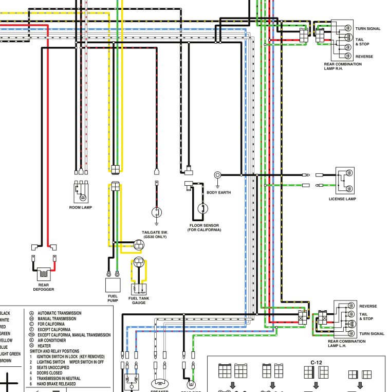
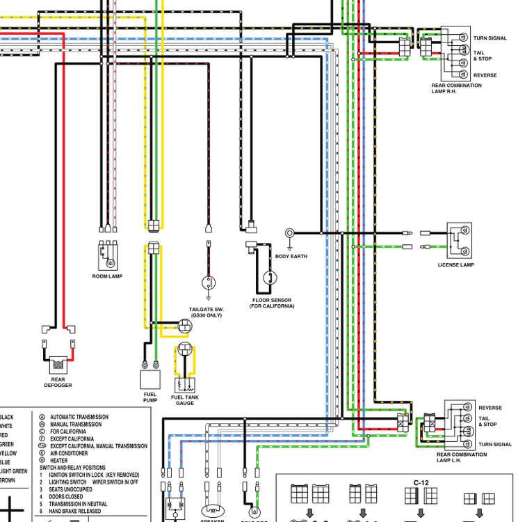
1 pointInteresting question. The 76 wiring diagram shows it as close to the license plate light. Rear of the car somewhere. Many other things branched in to it. I have a vague memory of something behind the plastic panel that covers the rear inside of the car, over the tail lights. I'll bet it's there somewhere. Easy to check, a few Phillips head screws. Nice and dry there, a good place for a ground connection. But if you think you have a bad fuel pump ground you might check the connector by the tank first. If everything else works.
 1 point
 -
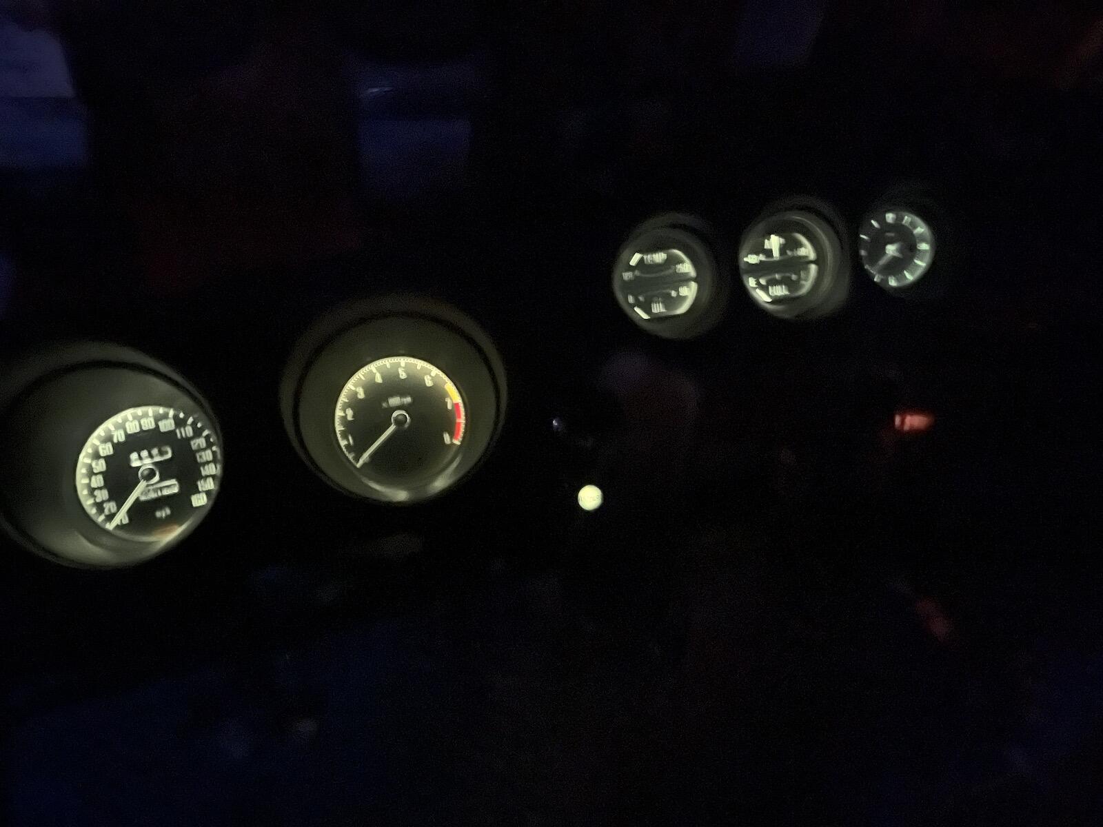
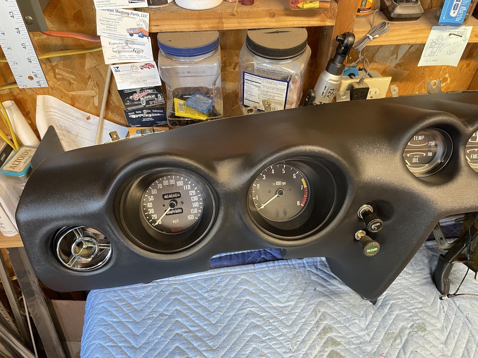
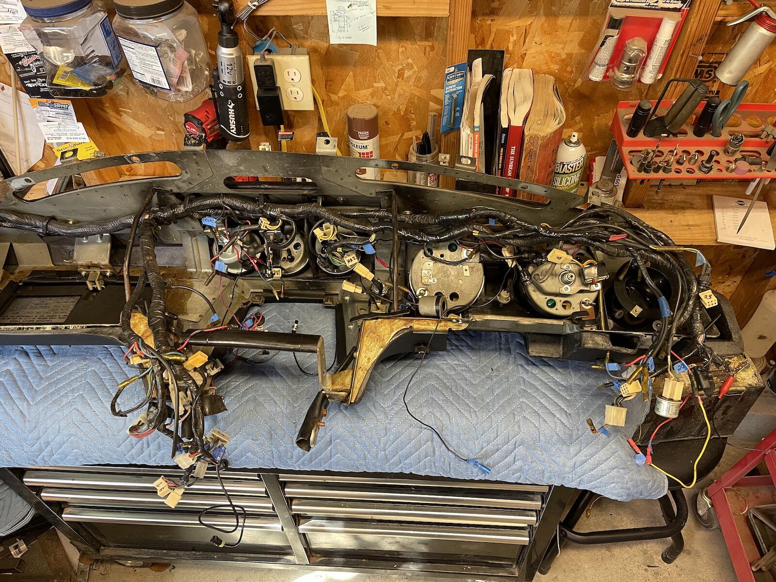
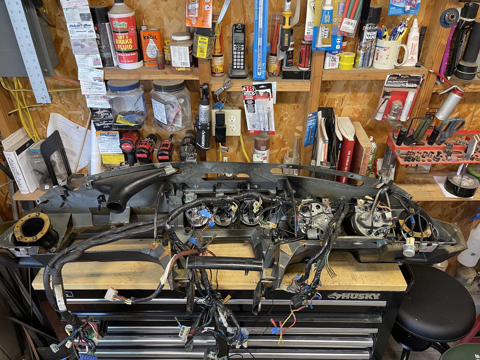
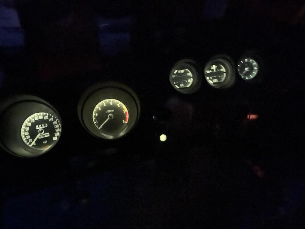
1 pointChanged all the dash bulbs using this kit from Z Car Depot. I prefer a dash that's not so bright, where I don't need to wear sunglasses at night 😎. So, used old school incandescent bulbs. Bench tested all gauge lights to make sure they all work and have good grounds. I'm ready to put this dash back in the car.
 1 point
 -
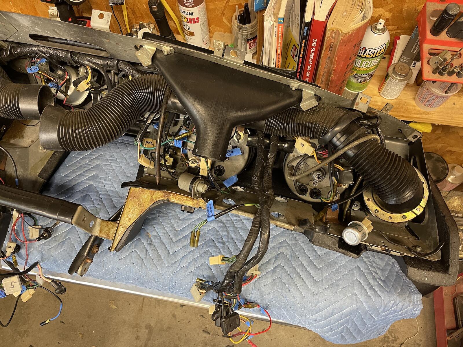
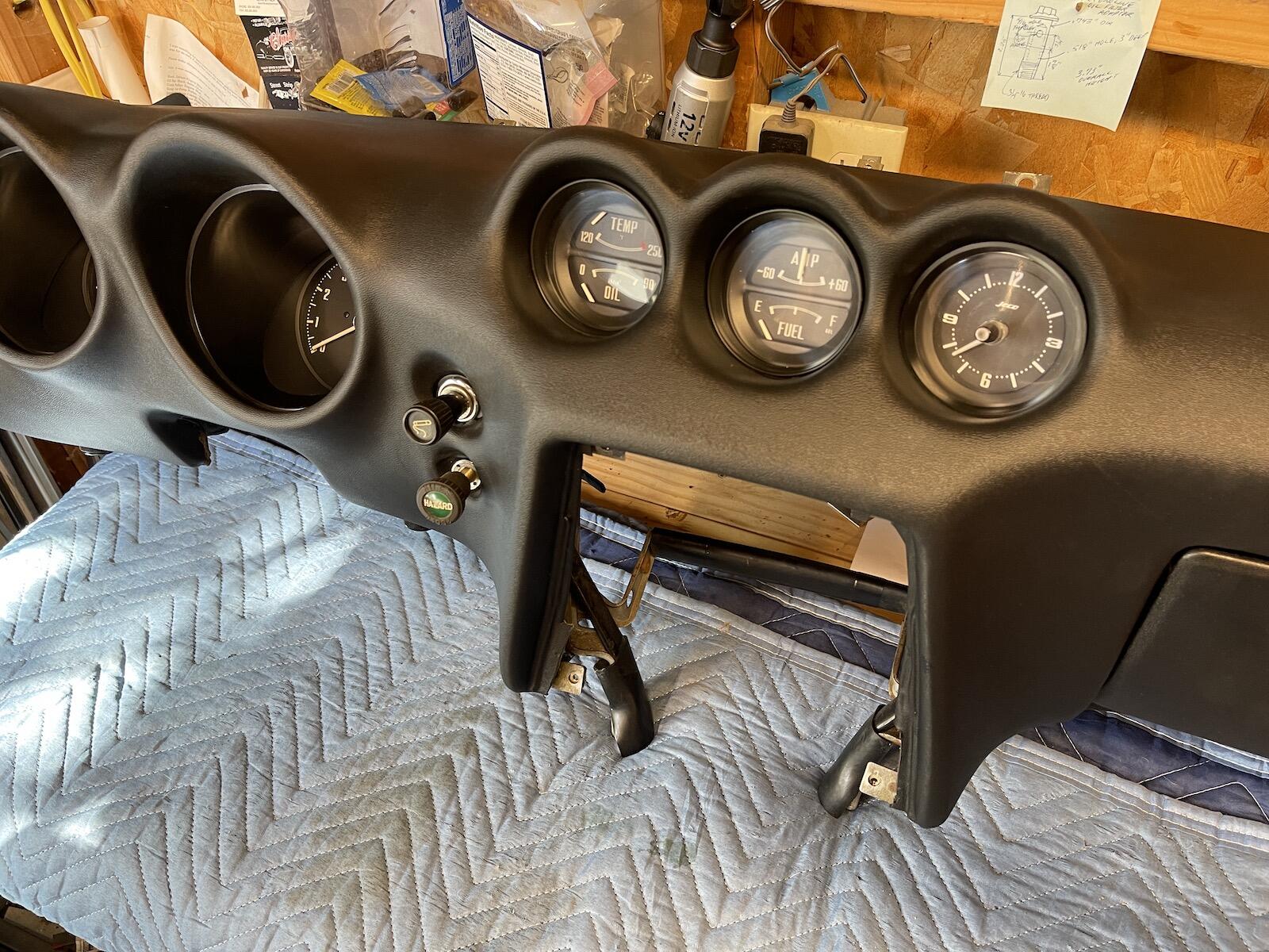
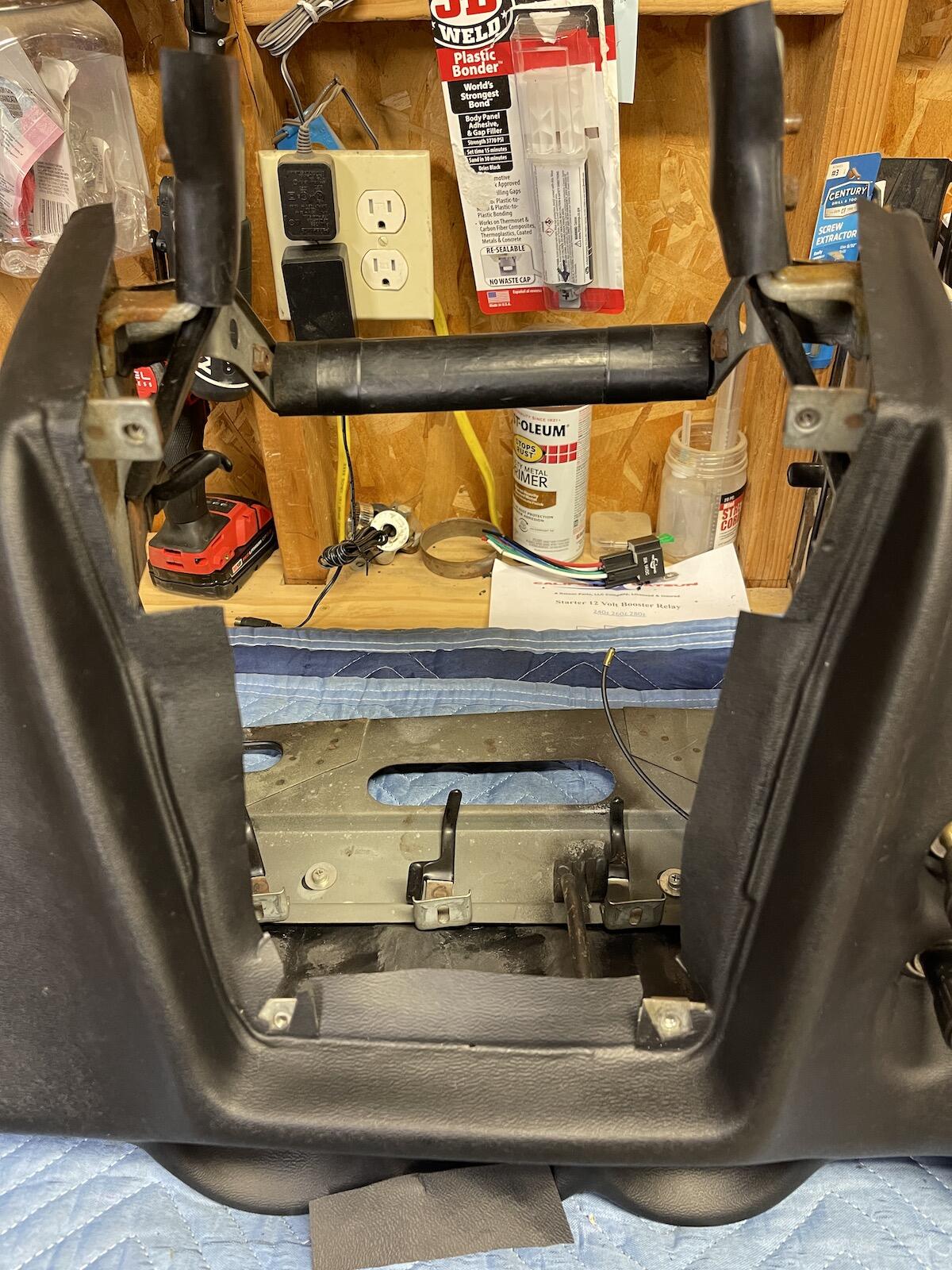
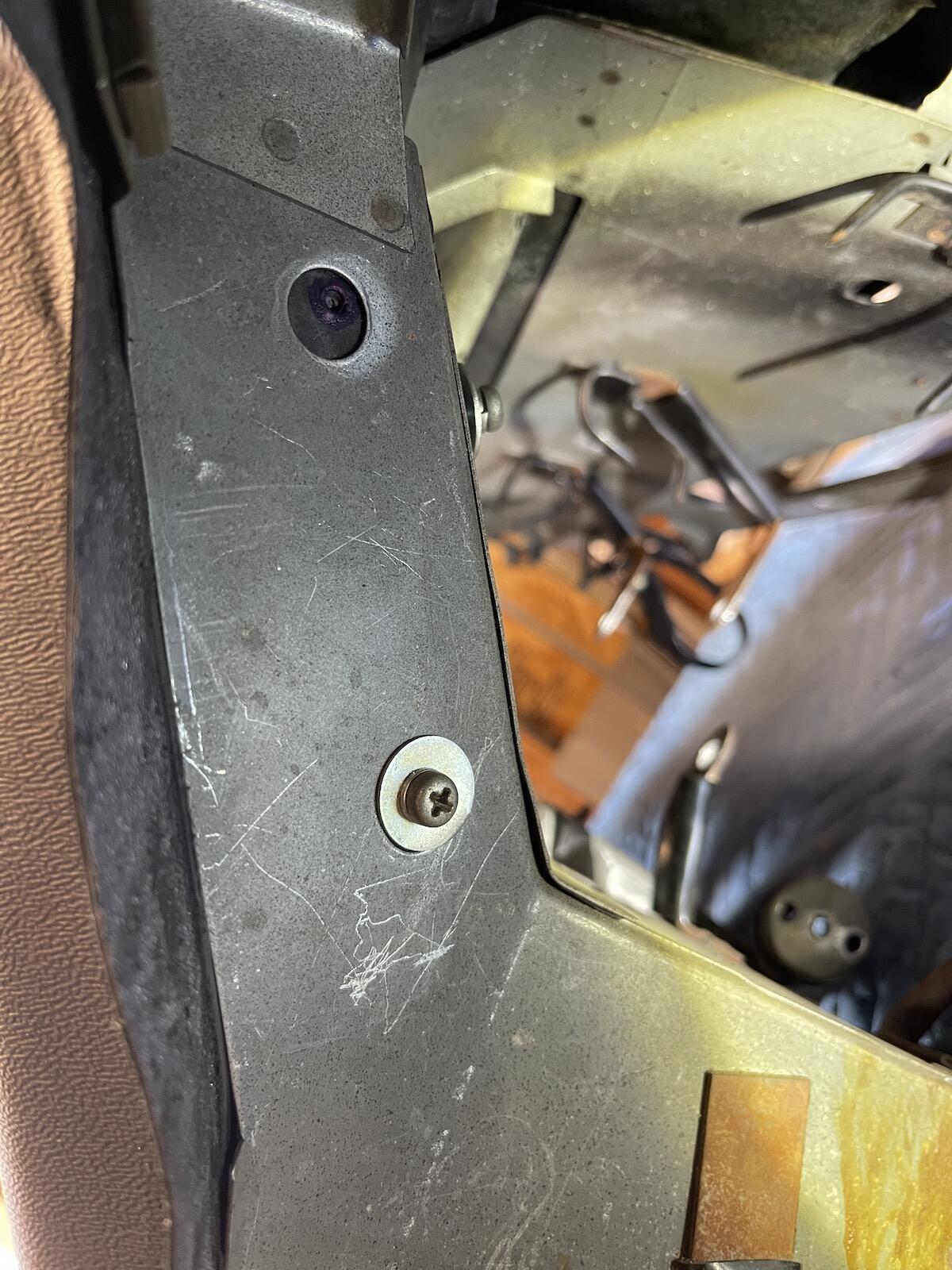
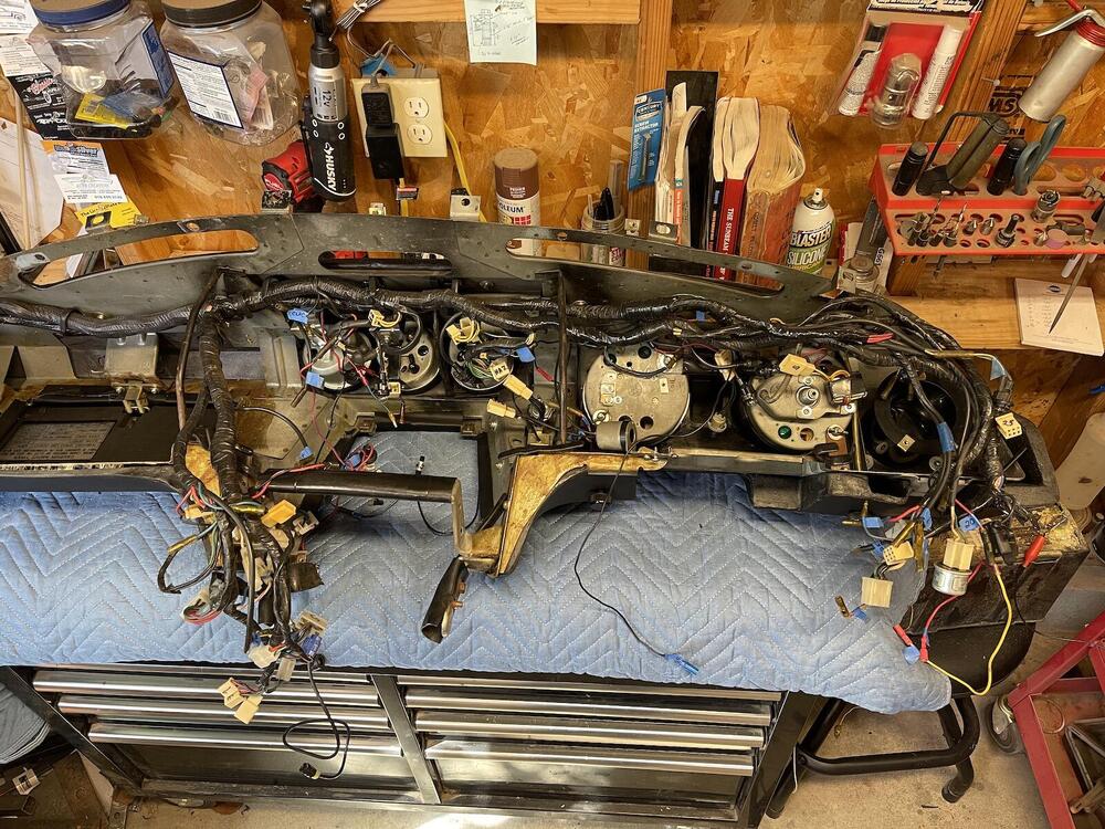
1 pointI'm going to try to reinstall the dash with everything connected behind the new dash, wiring, vents, glovebox, etc. So all I'll need to do is connect the harness at the right side relay area, fuse box, center console, and ignition switch. I'm not sure the new glove box can be folded like origami to fit through the front opening. But it was nice not having a glove box in the way when I removed the dash. I'm going to try installing it this way, but plans may change. I mounted a small push button and bracket (circled in red) to adjust the new clock when needed. I think I need to hunt up another person to help me get it in place, it is fairly heavy.

 1 point
 -
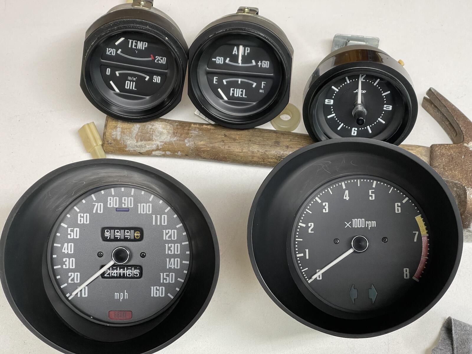
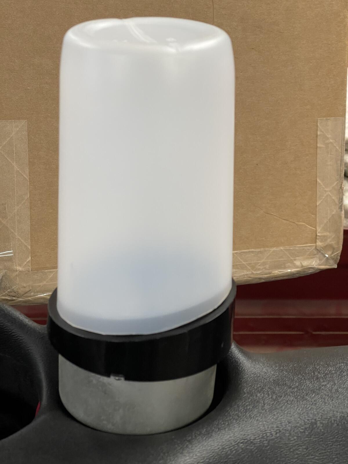
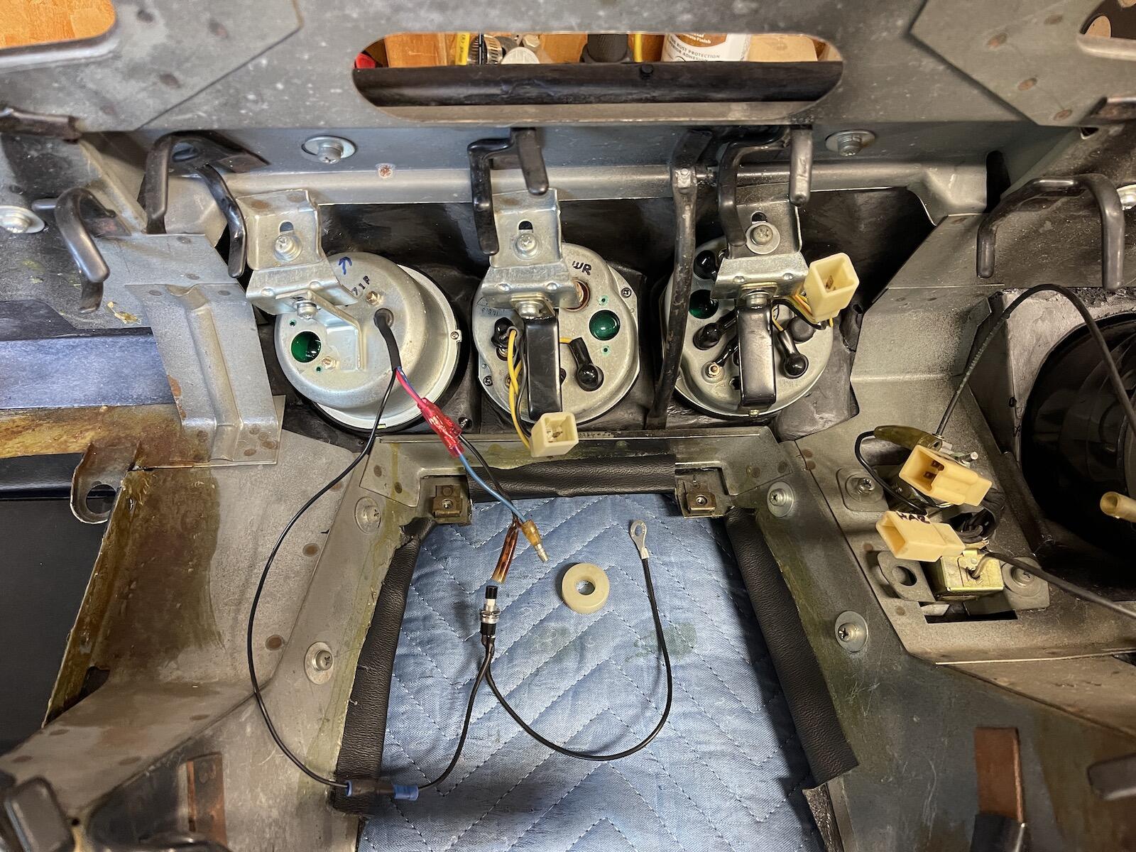
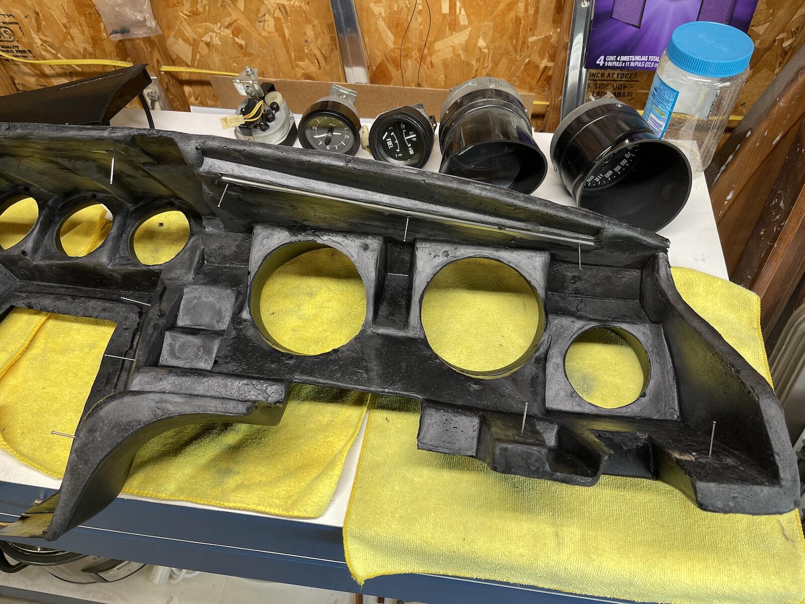
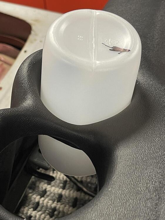
1 pointGot the gauges ready, clock converted, and right dial in the tach, and tested. I had a small paper gasket on the back side of the speedometer dial, around the needle shaft, that came loose, and it dropped down slightly covering part of the odometer, so had to take speedo apart to remove that. Cleaned lenses with Meguiar's PlastX, which worked good. As I was putting the clock back in the new dash, I noticed the dash holes were a bit tight, and had to pry the opening a little while pushing the gauge from the back. I didn't like the idea of prying on a new dash, even if it was a plastic tool. So, I found a plastic bottle, just the right size to fit through the dash hole, and fit around the gauge bezel rim, after cutting at a matching angle. And it was slightly tapered, smaller at the ending I poked through the dash hole first, wider at the gauge end. Once the bottle is shoved halfway through the hole, I put the gauge up inside the open end of the bottle and pushed gauge up against the back of the dash, and pulled bottle off. Worked great, plus no messing around the front of the dash gauge opening. I think it was a Clorox wipe bottle, but I'm keeping it! I'll bet the factory had something similar, but better. Gauges are mounted. Moved the old clock wires over to the new clock wiring, and have an adjustment switch ready to mount somewhere, not sure where yet. I also have this leftover part, that white spacer that fell out while removing the gauges. Can't for the life of me figure out where it goes, or even if it's needed. If anyone recognizes it, please let me know. 🤔 Now the fun part, connecting wires back up.


 1 point
 -
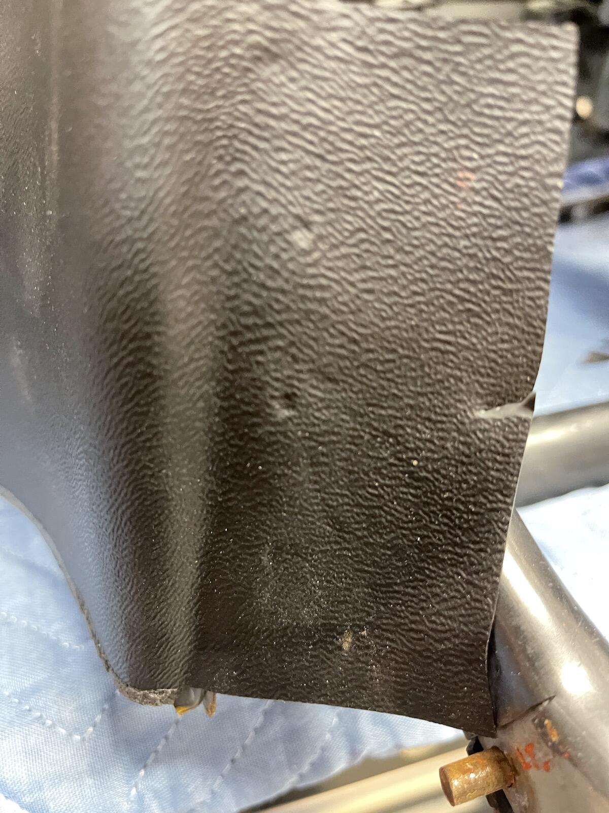
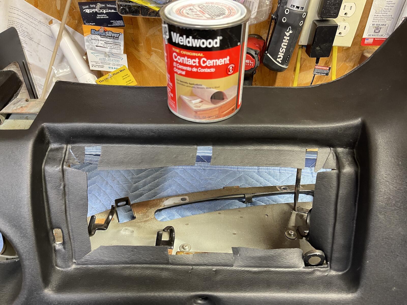
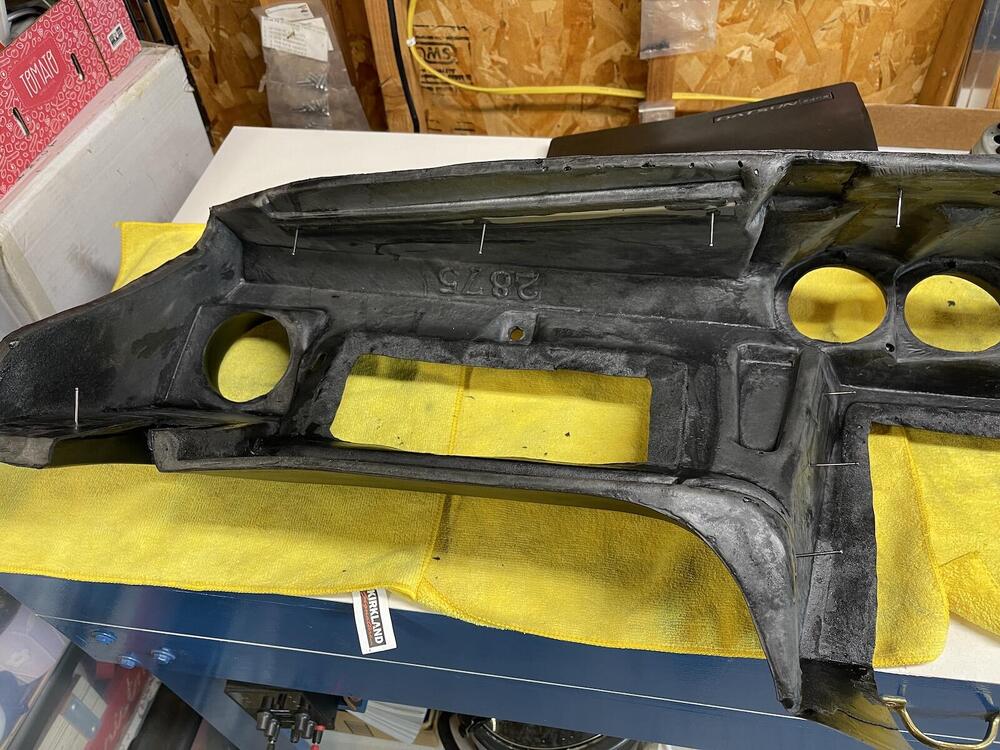
1 pointGot the center and glove box openings trimmed and ready to glue to the frame. I tried to generally match how the original dash was trimmed in the openings. Borrowed a friends solvent based Weldwood contact cement, hopefully it will hold good. I think these small dimples may be suggested cutting lines, I ended up cutting fairly close to them as I was trimming. Using stir sticks and clamps to hold overnight. I've got my 10mm 3/8" socket in the glove box button hole so dash is not getting deformed by the clamp. I ran out of clamps, so I'll finish the center tomorrow.


 1 point
 -
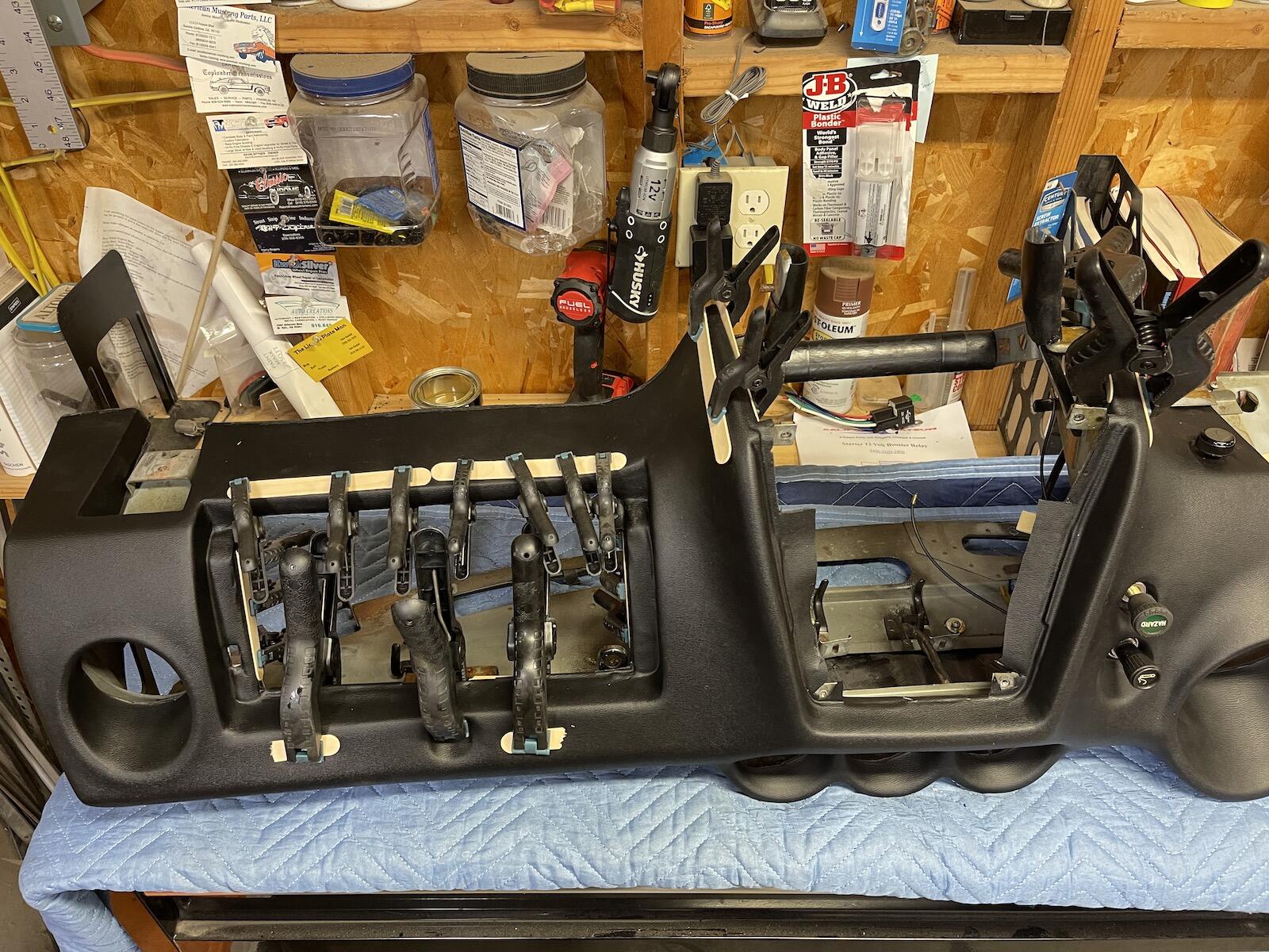
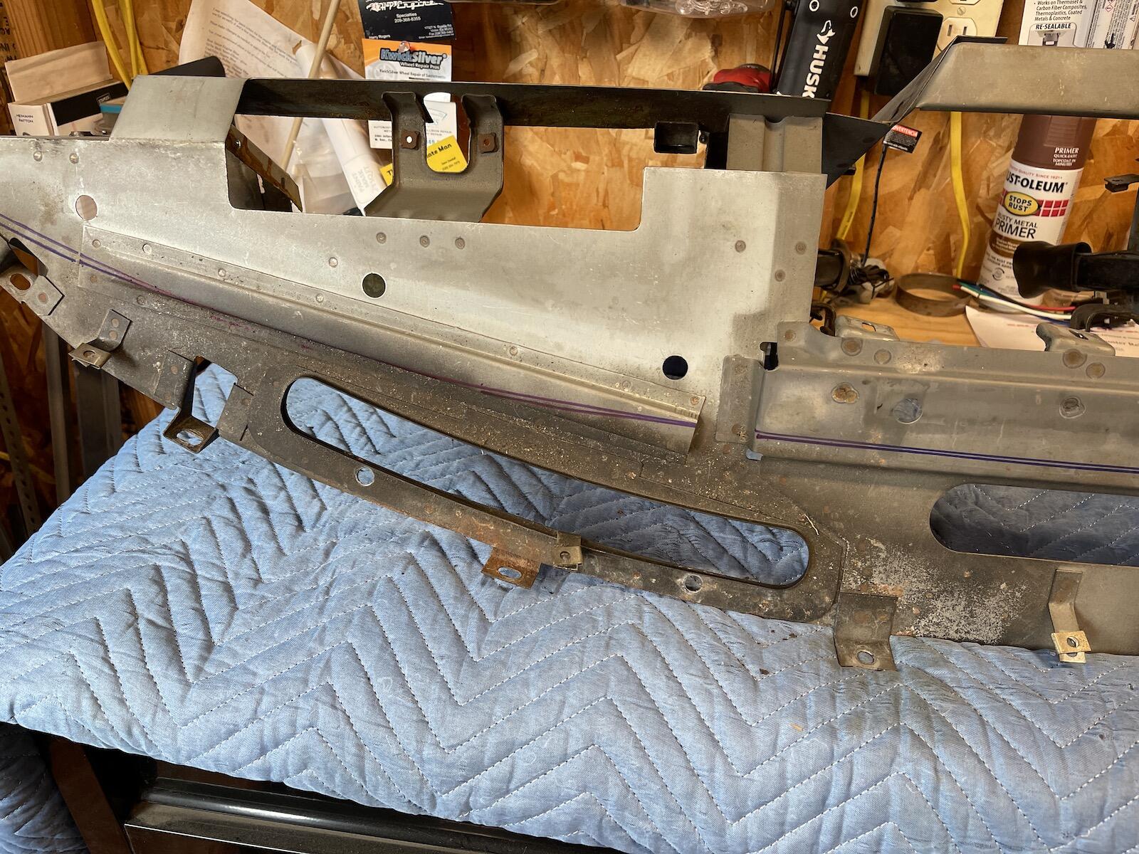
1 pointI screwed the vent panel in place and marked the edge, just so I know the top edge is forward enough to "hook" the top front edge of the dash pad when screwing pad to frame. Nice that the new dash has the same molded in place steel rails to screw into. There's 17 screws, here I've got finish nails sticking out of each hole. I should have ran a screw through each hole just to get a thread formed instead of waiting while trying to mount to frame. I also marked each hole with a marker which helped while positioning the dash over frame. I worked from the center outward.


 1 point
 -
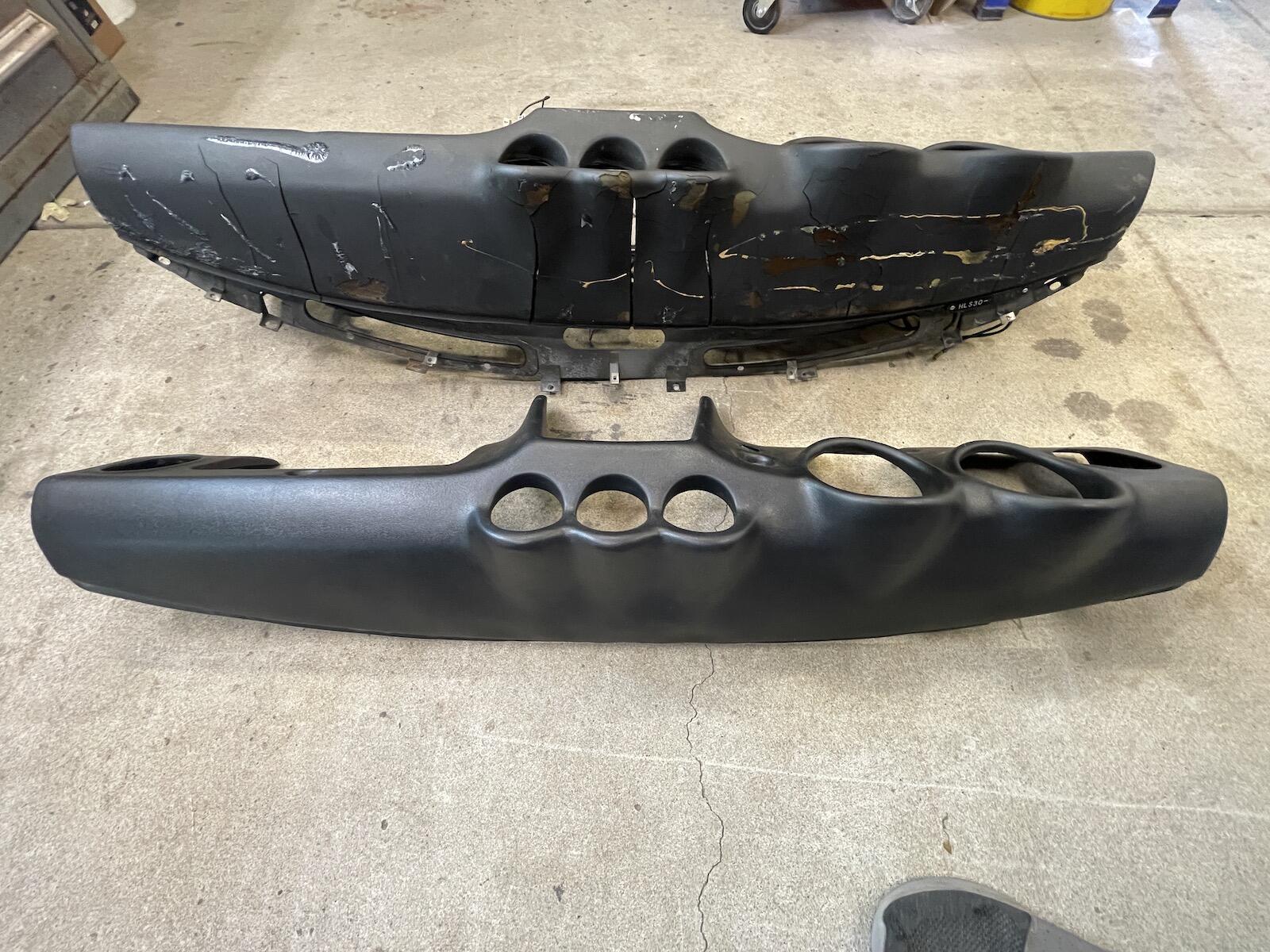
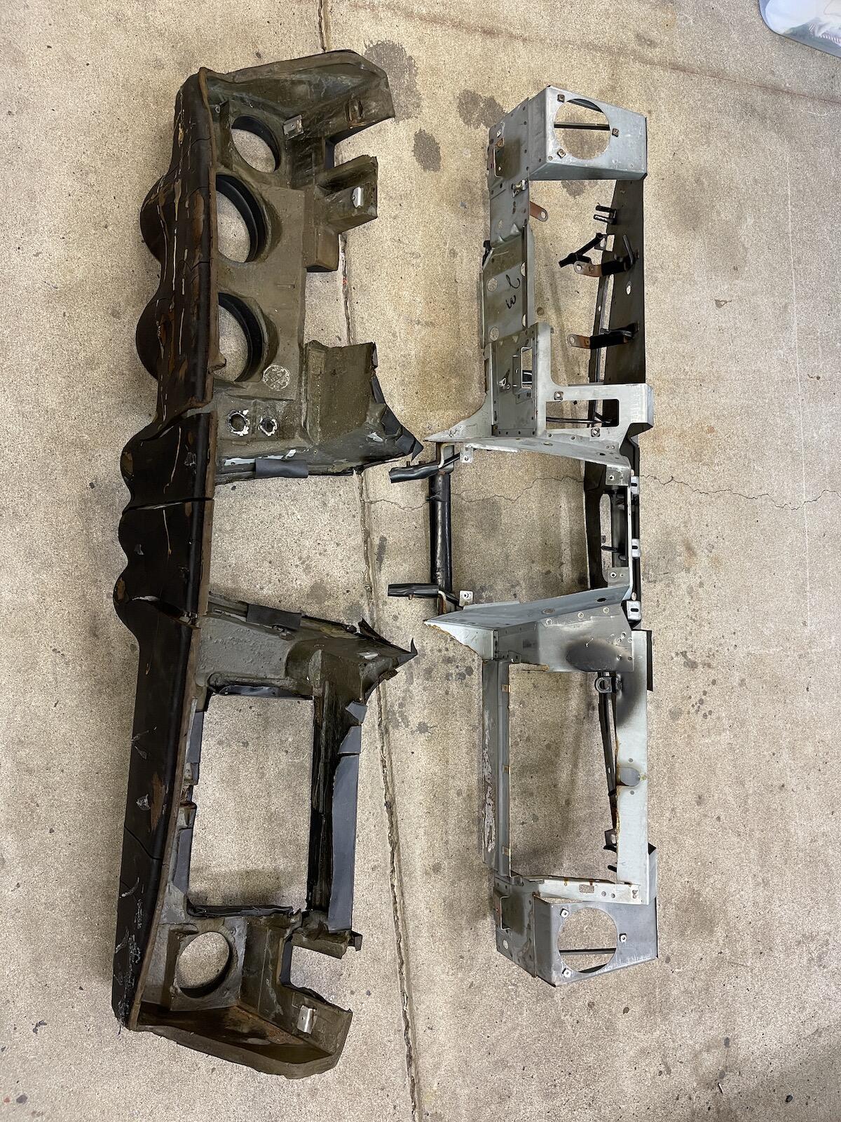
1 pointNow I removed the cap from the original dash. To remove the various knobs: Odometer reset: small set screw at speedo end, and pull knob off, remove cable. Hazard switch: push knob in, twist 1/4 turn counter clockwise. Lighter: 1" socket works to remove nut on back. Panel light knob: pull off, remove 2 screws from back. Luckily there wasn't too much adhesive holding the cap on, and it took about an hour of carefully prying it off the dash without cracking it. I'll probably sell the cap eventually. Once the screws that held the dash to the metal were removed, it slid right off.

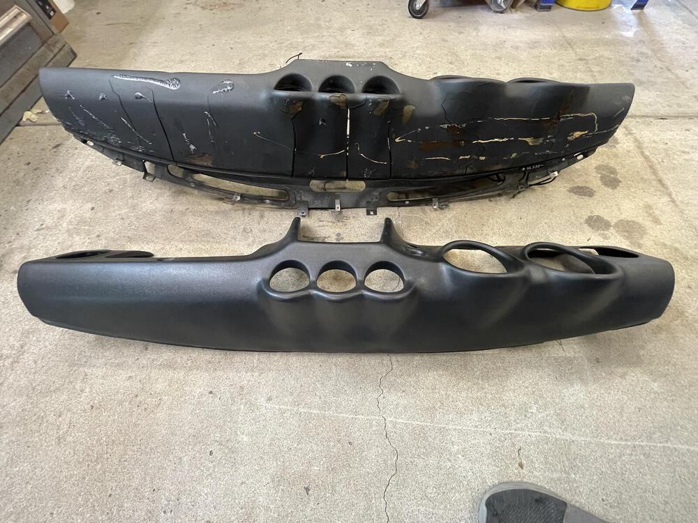

 1 point