.JPG.cfcada9cf1c1b502df3f5f2f2ca3ff36.JPG)

SteveJ
Community Member
-
Joined
-
Last visited
Everything posted by SteveJ
-
I'll have to see if she's up for an overnight. She's working again, so she has been a little tired...okay, a lot tired. She did seem tempted by the chance to be around dogs, though.
-
In looking at the 510 wiring diagram, for a manual transmission wagon, I think this is how the wiring is without the tachometer. BW comes off the ignition switch and goes to the fuse box. While one branch goes to a fuse holder, another branch goes to the ballast resistor via a fusible link. From the ballast resistor, the wire is BL. The BL wire goes to coil positive. When starting, the BL wire is hot from the ignition switch. With the tachometer, I think this might be how the wiring should be BW comes off the ignition switch and goes to the fuse box. While one branch goes to a fuse holder, another branch goes to the ballast resistor via a fusible link. From the ballast resistor, the wire is BG (maybe?). The BG wire should go to the dash for the tach and come out BL. The BL wire goes to coil positive. This may be backwards. The challenge is that I have yet to find a 510 wiring diagram that shows the tachometer and is very clear on the wiring. The one I used to find the BG wire color leaves much to be desired. It was created by a 3rd party. What looked to be a Datsun FSM BE section didn't even show the ballast resistor. It might require that I pay you a visit to work that out, @Patcon. B - Black L - Blue G - Green W - White @Patcon There is a place not too far from me that does car instrument repair. http://www.hampspeedometer.com/ You might want to see if they can test/fix the tachometer. Datsun_510_Wiring_Diagram_1971_Wagon.pdf
-
While I said the wrong thing in the video, off camera I put the meter in 4 cylinder mode and found out that the 510 tach should have registered higher.
-
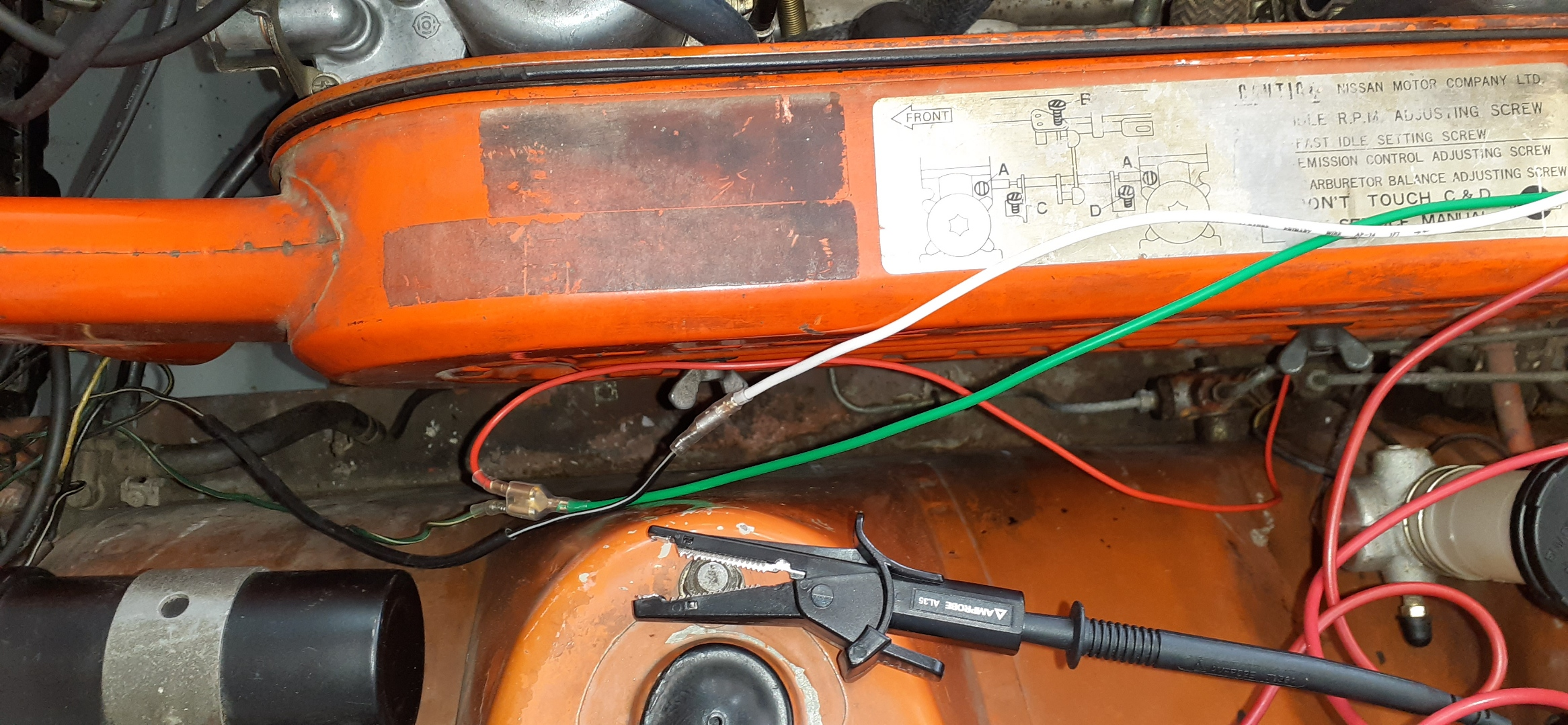
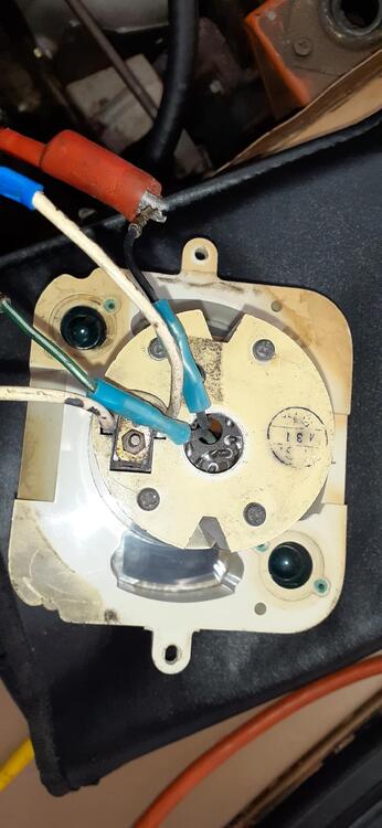
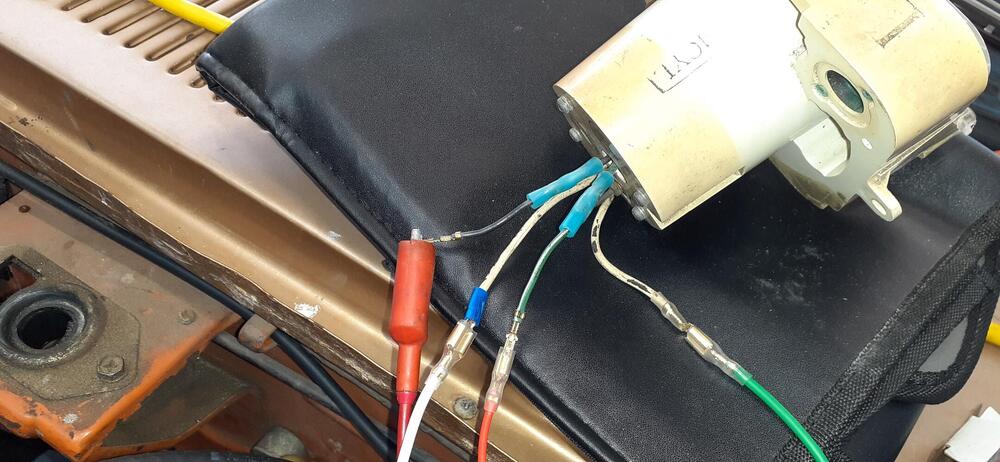
A while back, @Patcon sent me a 510 tachometer to test before he and Cody attempt to install it in the car. It's similar to the 240Z tachometer with the inductive loop and the power. I finally got the testing up to the top of my list, and today was a great day to be in the garage with the summer heat not as strong as usual. I wired the tach into the ignition of the 240Z. I deleted the ballast resistor when I installed the Pertronix last year, so I could unplug the bullet connector joining the black/white wire to the green/white wire. I tapped that circuit for tachometer power, too, grounding the tach on the strut tower with a clip lead. The tachometer does respond to changes in engine speed but not much nor rapidly. I'm not sure if it was an impedance issue for that tachometer since the coil is only 1 ohm. I neglected to look at the tachometer in the car while testing since I had a meter connected to give me a reading. In normal operation, the tachometer in the 240Z works fine. So I can see that the tachometer works, but it doesn't work great. I'm not sure if it was something I did or something with the tachometer that caused the results. What do you think, @Captain Obvious? @Zed Head, do you see anything? Back of tach Connected to the Z Wiring at the ignition And here's the video

-
Yep. That's the kinky part of engine porn.
-
An air pocket would reduce heat transfer, and the reading would go down. The sender works by decreasing resistance in proportion to the increase in temperature. Do what Steve @madkaw said.
-
Now I have to get some kleenex to wipe up the oil that I spilled on the floor. 😉
-
@zclocks Ron, do you have an answer?
-
Who is looking for some wall art? https://www.sportscarart.com/product/datsun-240z/ https://www.sportscarart.com/product/bre-datsun-240z/ For the BRE design, the artist consulted with Ron Carter, Randy Jaffe, Peter Brock, and John Morton, so there was quite an effort to get the details right.
-
I don't mind waiting. The early birds can help find the problems for Nissan before I buy.
-
Pseudo AN fittings (hose clamps) https://www.amazon.com/gp/product/B07KLJSVKK/ AN hose to hard line adapters https://www.jegs.com/i/JEGS/555/110557/10002/-1 You can even replace the SU banjo fittings with AN banjo fittings. https://www.summitracing.com/parts/ear-at807691erl?seid=srese1&gclid=CjwKCAjw0dKXBhBPEiwA2bmObUdWw3ZXoVZg9t8sVxlQMFPw1q4Nr-rL82MjCkkosyN3yLs8j0bBNhoC-ewQAvD_BwE
-
Remove the wire from the oil pressure sender and short the wire to the chassis. The best way to do this is have a wire with an alligator clip on one end and a normal male bullet connector on the other end. Clip the wire to the shock tower or negative terminal of the battery and connect the bullet to the wire for the oil pressure sender. Go in your car. Put the key in ON (don't start the car) and watch the oil pressure gauge. If it shoots up, you probably have a bad sender. Definitive diagnosis would be to confirm with a mechanical gauge. See this thread for info on installing a mechanical gauge:
-
https://www.nissanusa.com/shopping-tools/build-price?models=nissan-z&modelYear=current-year&fbclid=IwAR3VhDgFxlqXCyDxa7czP5UL5ZPug_uOvxB9UUFeursKsFuBawUUdfZ67Bw I'll wait until they have the color I want. Two sources in Nissan said it is coming.
-
And the link I provided is also for Hung Vu for the people who do not use Facebook.
-
I'm not surprised. It was probably to simplify the dies for stamping the bumpers..
-
Here's a way not to worry about that fuse: https://www.amazon.com/NOCO-GC017-Adapter-Socket-Battery/dp/B00G8WLX78/
-
Not sure, but I would worry about metal shavings getting into the head/engine.
-
According to ZCarSource, this is a P90 head. You can see that the window for the fuel pump hasn't been opened up. On the N47 Maxima head in my 260Z, I put a cover plate over that area that I bought from MSA.
-
This may not answer your question, but I thought the info on this page was interesting with regard to Datsun keys: http://datsun1200.com/modules/mediawiki/index.php?title=Keys
-
If you haven't already done so, download the FSM. It is available for free from this site. In the ET section, it shows you what you are looking for on page ET-11.
-
If you're referring to Vintage Dashes, they have a contact link on their website: https://vintagedashes.com/pages/contact
-
The hazard switch has a bulb. It should come on with the parking lights/gauge lights. Here is some fun I had with that bulb socket 4 and a half years ago.
-
I think larger units tend to intrude into the passenger footwell. I think AC Autosolutions sells a kit that only partially intrudes into the footwell. A friend said he has talked with the guy who runs AC Autosolutions, and the guy is easy to work with. I noticed that on his website, there is some carpeting hanging down from under the dash to hide the evaporator. https://autoacsolutions.com/products/ac-kits/add-on-air-conditioning-heat-and-defrost-air-kit-with-integrated-controls-for-75-76-77-78-280z/
-
To your point, @HS30-H, I asked my wife to do a light sanding and stain the steering wheel in my car. She used a regular wood stain and sealed it. The wheel took the stain great. I doubt "plastic" would have faired so well, and my wife, who has stained a lot of wood over the years, confirmed my doubts.
-
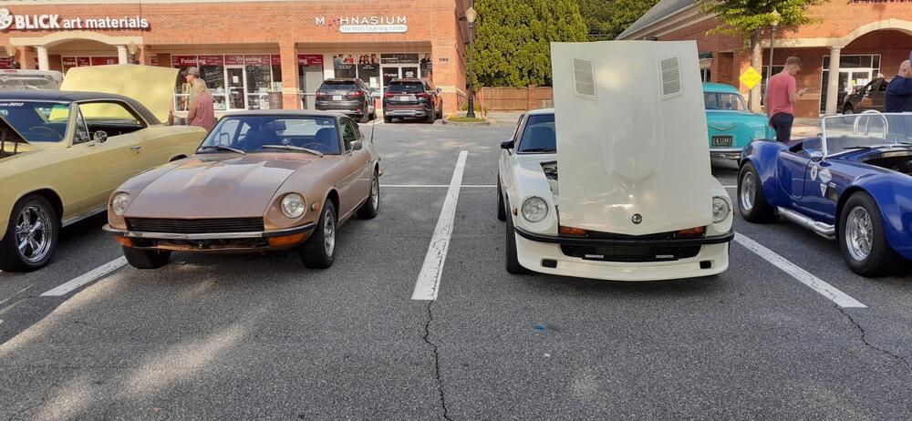
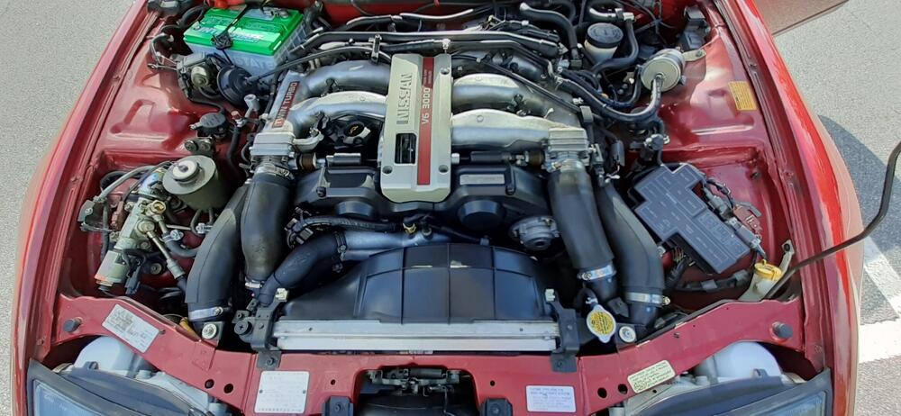
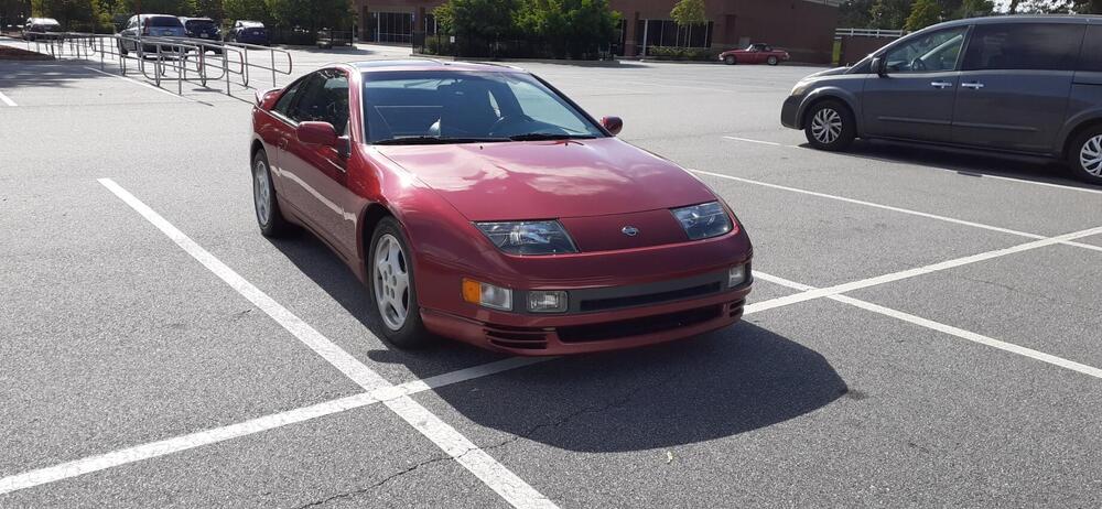
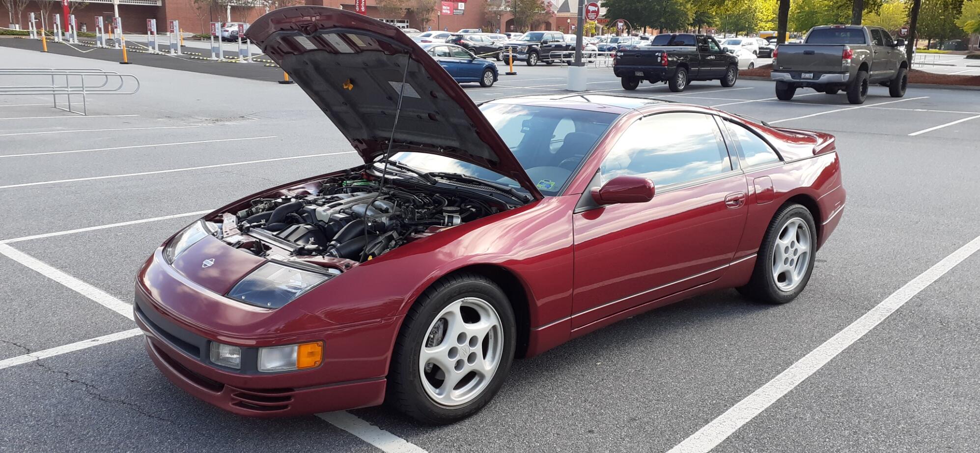
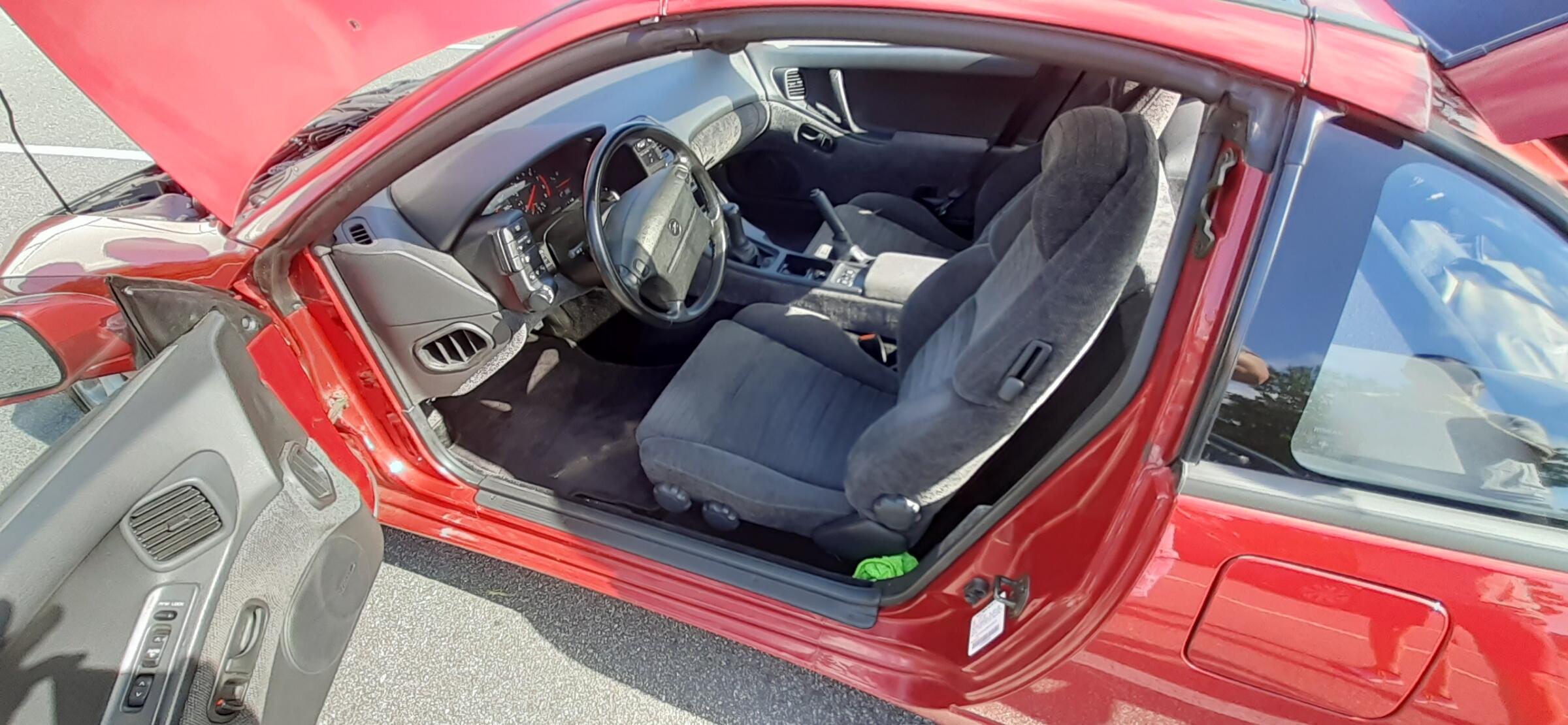
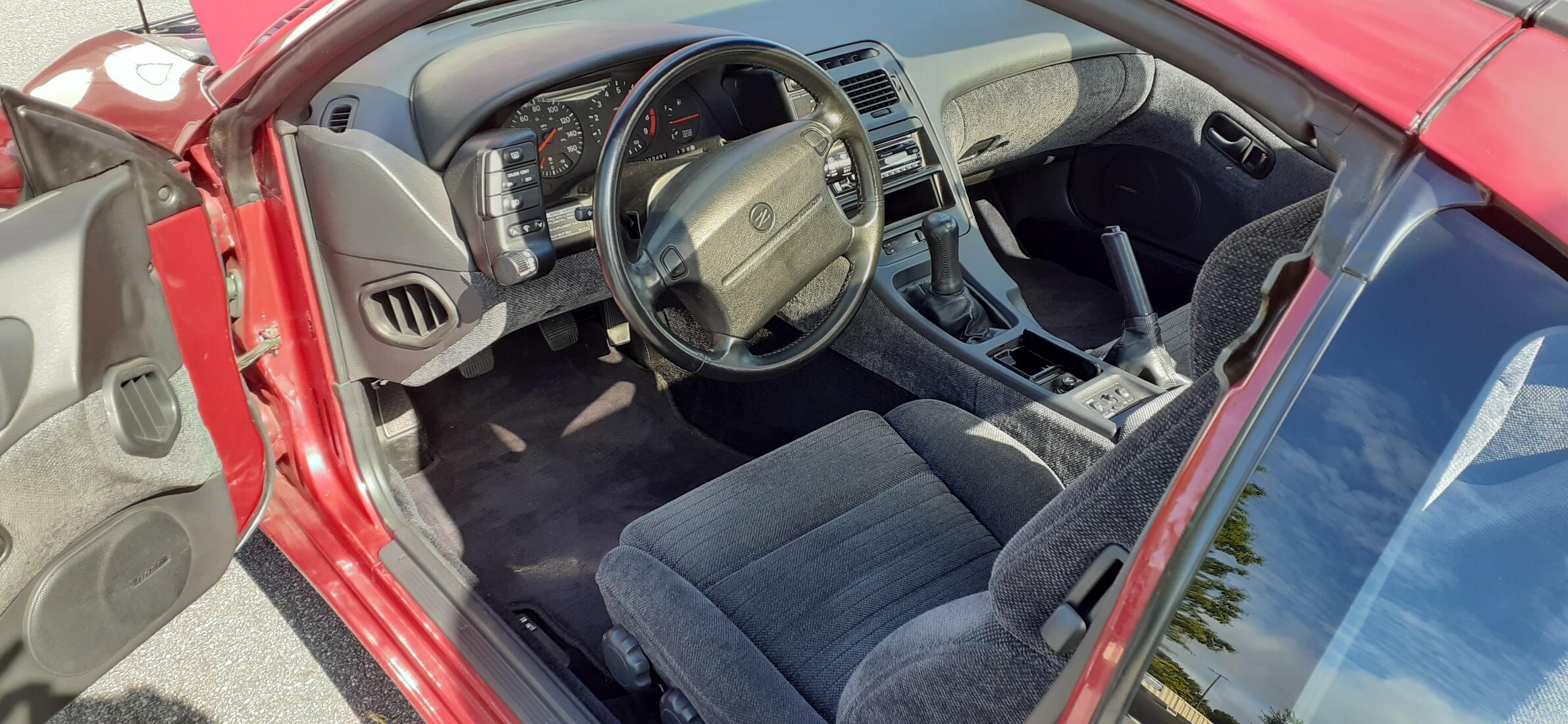
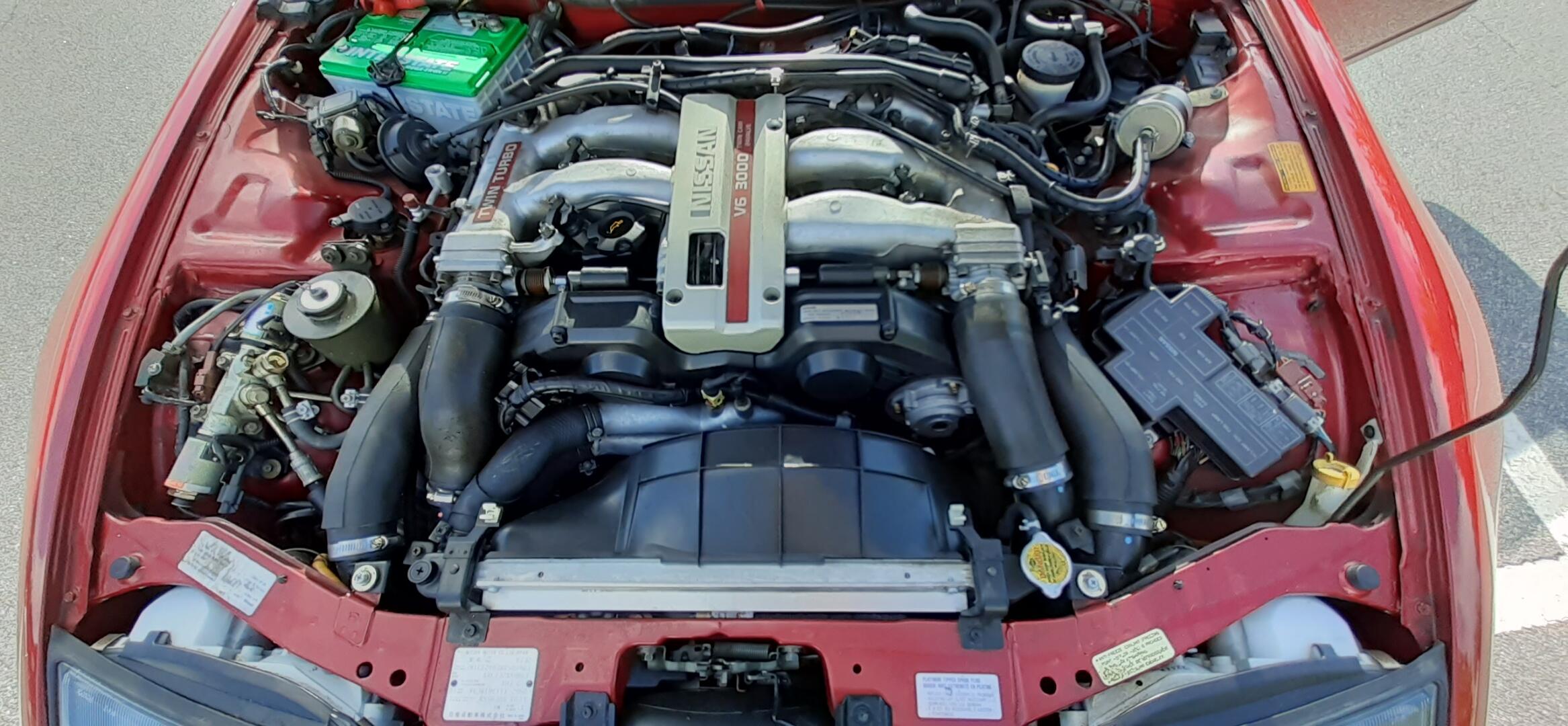
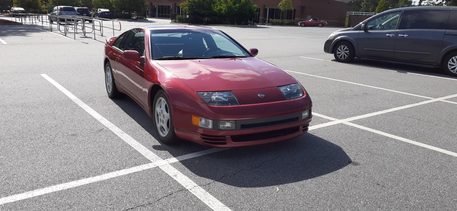
Today was a great day to go to the Worship car meet. The weather wasn't too hot, and I found a good parking spot that afforded me some shade for most of the time I was there. There were 2 280Zs, 2 Z31s that showed up, and then there was the time capsule. Sandesh introduced himself to me and said he brought his 1991 Twin Turbo but parked it on the other side of the sea containers in the parking lot. David and I walked over with Sandesh to see his car. It was well worth the effort. Sandesh said he purchased his Z32 with 3K miles in 93. It now has a little over 23K miles. The interior is immaculate, and it wouldn't take too much to get the engine bay ready to win a ZCON Gold Medallion. He still has the original Goodyear Gatorbacks on the rears. I might have to see if I can convince him to buy a Nissan battery. He has been an incredible curator of this museum piece, and I'm so glad he brought it out for us to see. Here is my car with a nice 280Z owned by a friend. And here is the time capsule...