inline6
 Subscriber
-
Joined
-
Last visited
Everything posted by inline6
-
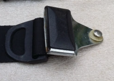
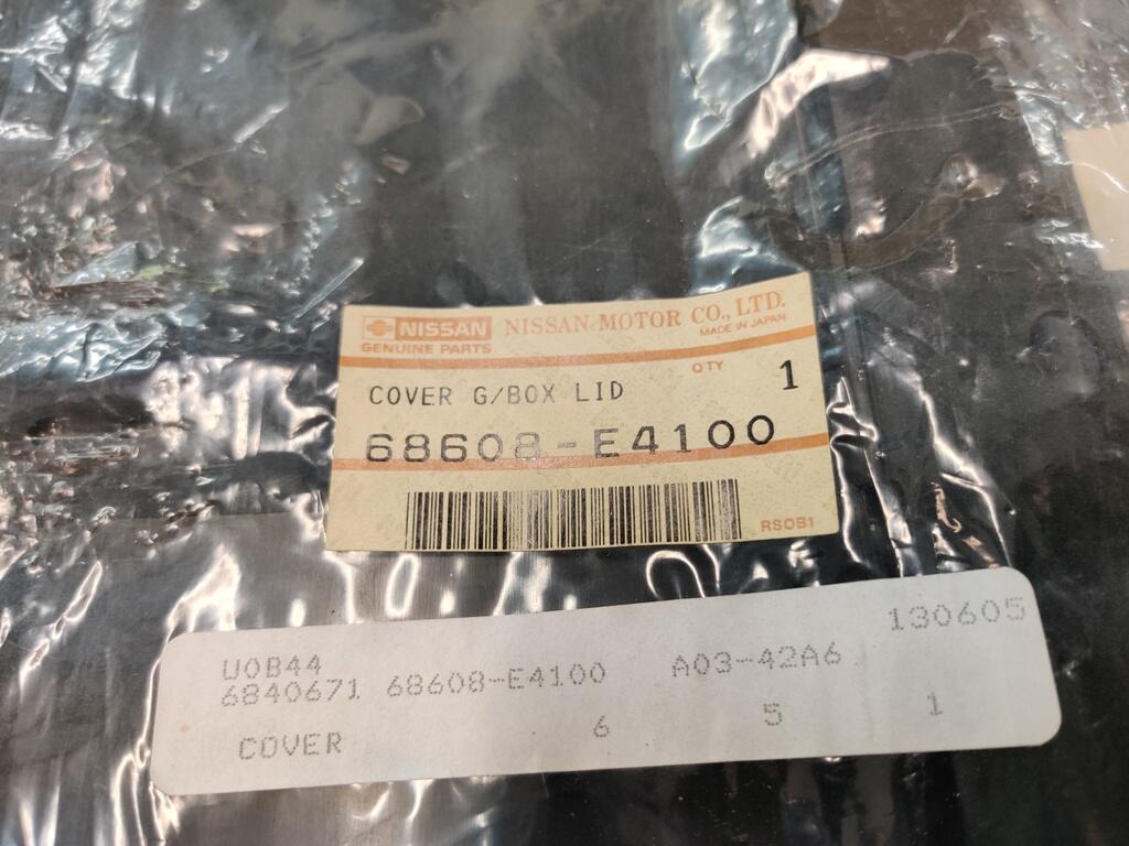
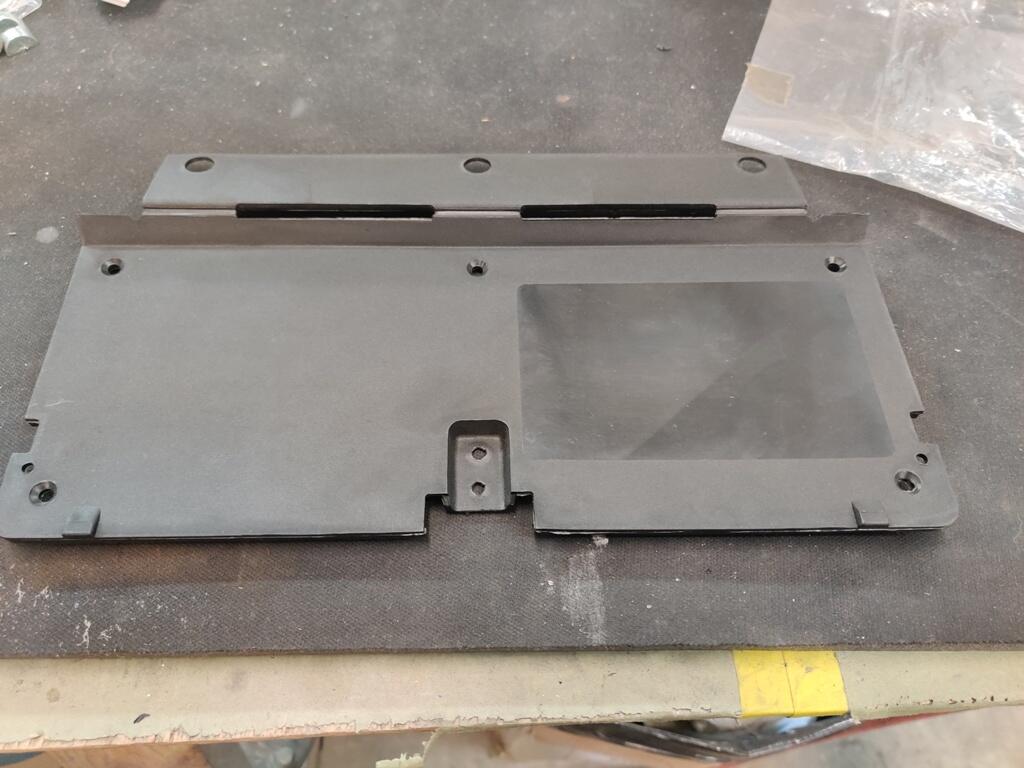
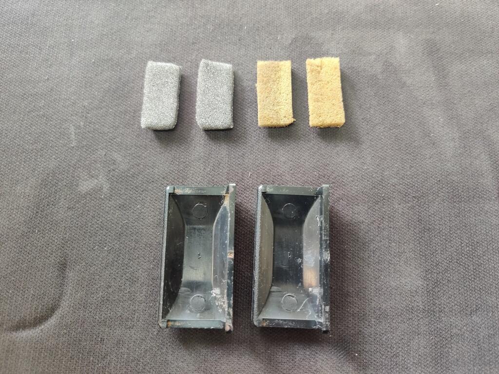
 While I have turned much of my attention to my other 240Z recently, there are still quite a few things on the to do list for this car. One of them was replacing the glove box hinge/panel. My old one had broken at one of the three hinge areas. I was lucky enough to find a NOS one. Having recently replaced the decal on the original one with a new decal, I had to procure another new decal, and put in on this new panel. I still have some alignment issues to work out before the glove box will shut properly. The Vintage dash that is the car requires a bit of trimming of foam and vinyl on the lower edge of the glove box opening to allow the hinge to operate properly. Another small item on my list was to install these plastic seat belt buckle trim plates (old foam on the right, new on the left, which I glued to the center backside of the trim: These go here on the 1971 belts: I used a heat gun to warm them up quite a bit before snapping them into place, which went without issue thankfully. I still have a bunch of details like this that need to be completed. I would like to swap out the headlights bulbs for some other Koito H1 type ones that I found which look more like the originals. There are various other markings I'd like put in place to replicate factory ones (paint markings). I also would like to get the original wheels refinished and get some stock sized tires mounted on them. The original hub caps that I have are very nice, but if I can get better results with the paint color experimentation, matching the original much better than my efforts thus far, I will refinish them. I still haven't done anything to address the lean condition that I am experiencing. So, that is still on my list. After about 4 rounds of pulling the valve cover off to adjust the valves (the valve noise was much more than I can recall with my other L series engines), I figured out part of my problem. I have generally been adjusting valves with the engine cold, but sometimes when it was kind of warm as well. I was sure it would tighten up as the engine got warm. What I have found instead is the the lash clearance actually grows a bit when the engine warms up. The specification for my camshaft is .006" on the intake and .008" on the exhaust. I started off with setting the clearance at that spec with the engine completely cold. I then found that the lash was a bit larger with the engine lukewarm and a bit larger still with the engine hot. Seeing this, and after resetting lash a couple of times prior with no improvement, I decided to use .005" and .007" while the engine is cold instead. With that I achieve notable improvement.


-
https://www.pontevedrarecorder.com/stories/73-nissan-z-race-car-to-be-exhibited-at-ponte-vedra-auto-show,150339
-
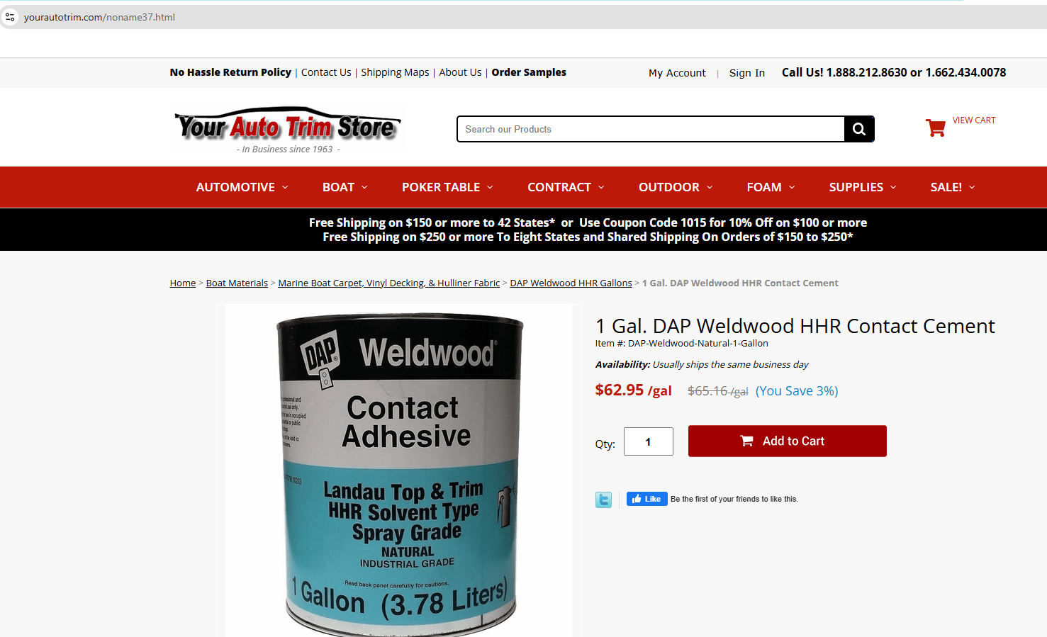
I really like this stuff for all adhesive needs: 1 Gal. DAP Weldwood HHR Contact Cement You may have to clean some weatherstrip of its "mold release" before trying to glue it in. A little lacquer thinner on a rag and a few wipes on the surface to be glued is all that is needed. For door weather strips, I use an acid brush, start in the sharp corner at the top, back of the door. You can do it in sections about 18 inches long. Just apply adhesive to both surfaces, wait about 3 minutes, and then press and stick. It is going nowhere after that.
-
It is buy it now for $40k. I told him to emphasize that the original mileage is 51k and to add some pics of his documentation... pics of the various VIN plates and VIN on the firewall, and pics of the engine number on the block and the E31 on the head. I see he has added the documentation and the engine compartment tag already. I know the market is a lot softer now for these than it was, but I think it will sell for the $40k.
-
I have been watching this one for a few weeks. Couldn't get it out of my head, as it has an extremely clean and mostly original interior. Miles claimed at ~51k. Since it is only an hour a way, I went to look at it. The current owner is a son - this was his father's car. He has some documentation going back to 1972 which does have mileage on it. He has two or three documents - enough to support that the mileage is accurate. Also not clear in the listing is that it is a matching numbers car - original engine and head, as well as the original 4 speed. The original spot welds are present even in the rear fender wells at the bottom (rocker). The car has never had any rust through. He also said he has the original hardware (replaced with stainless) and the original front, lower panels (left, center, right). The paint is daily driver grade. In my opinion, to take this car to the next level, it would need a full exterior and "door jamb" repaint. Floors and hatch area and engine compartment still have the original silver paint. eBay1971 Datsun Z-Series | eBayFind many great new & used options and get the best deals for 1971 Datsun Z-Series at the best online prices at eBay! Free shipping for many products!
-
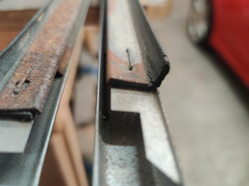
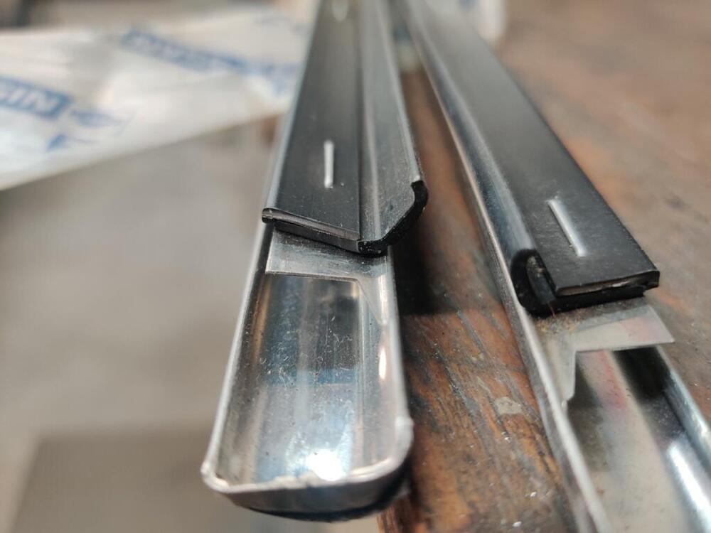
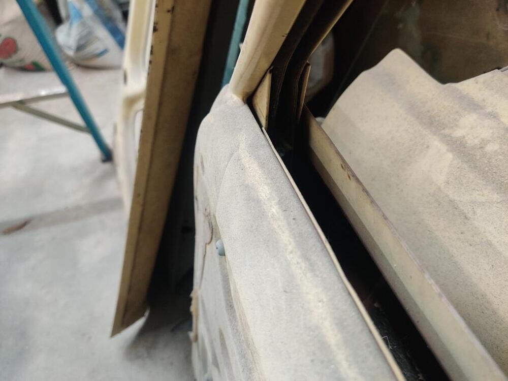
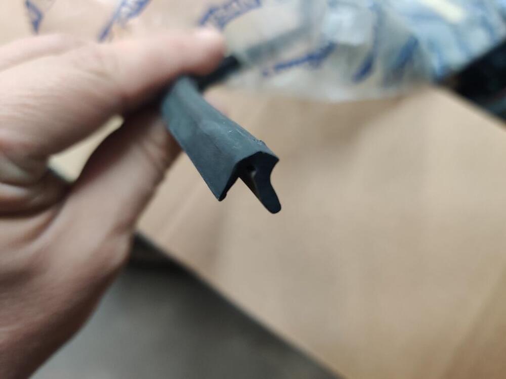
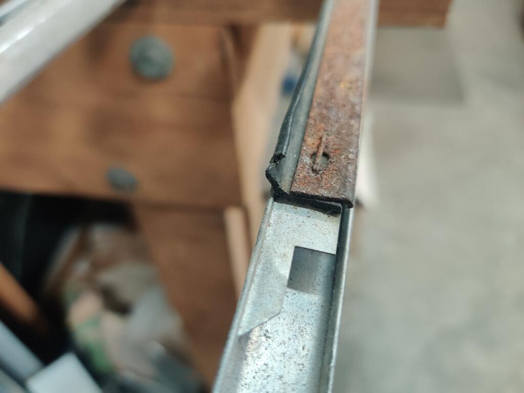
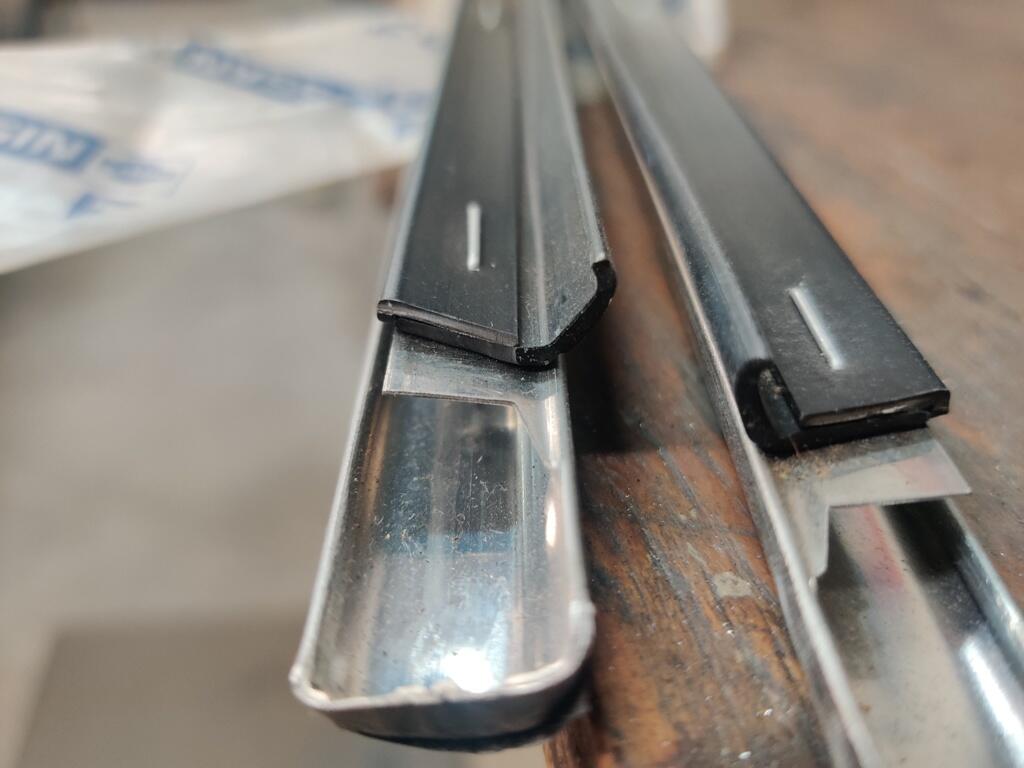
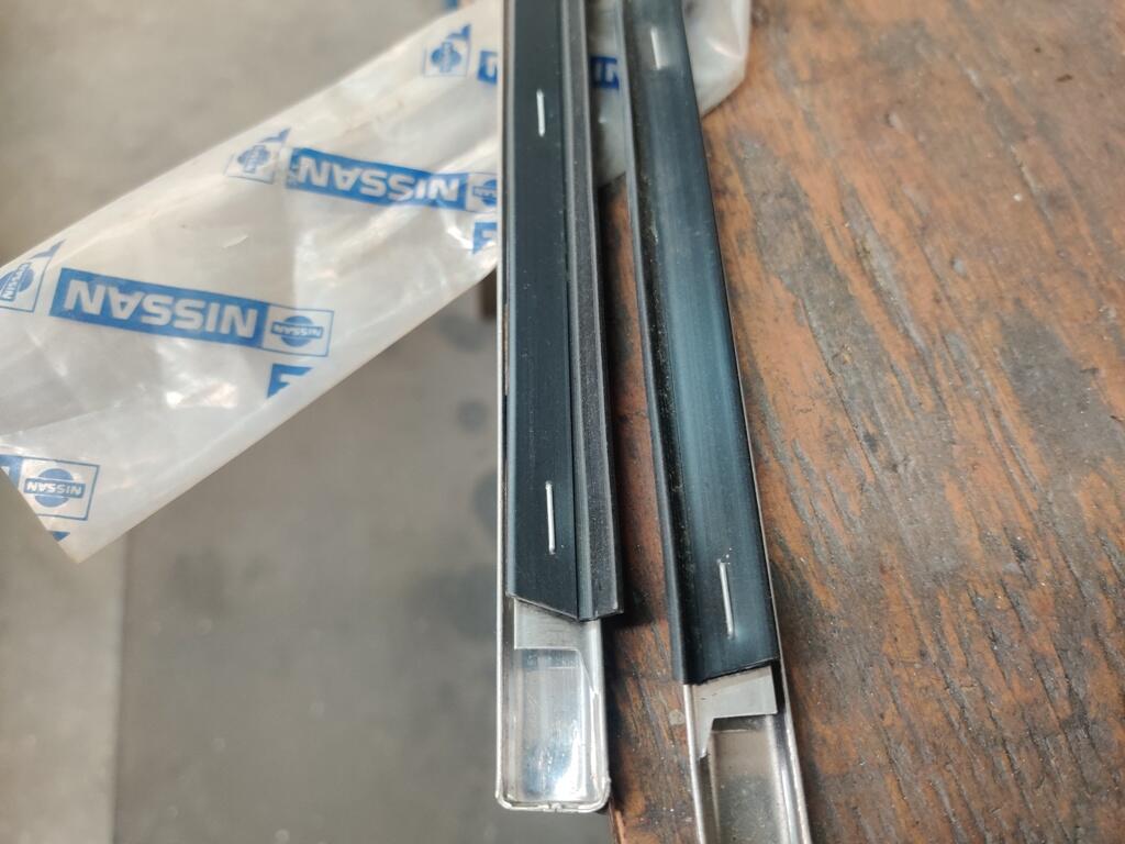
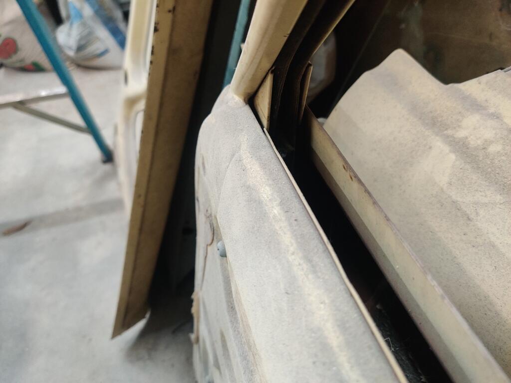
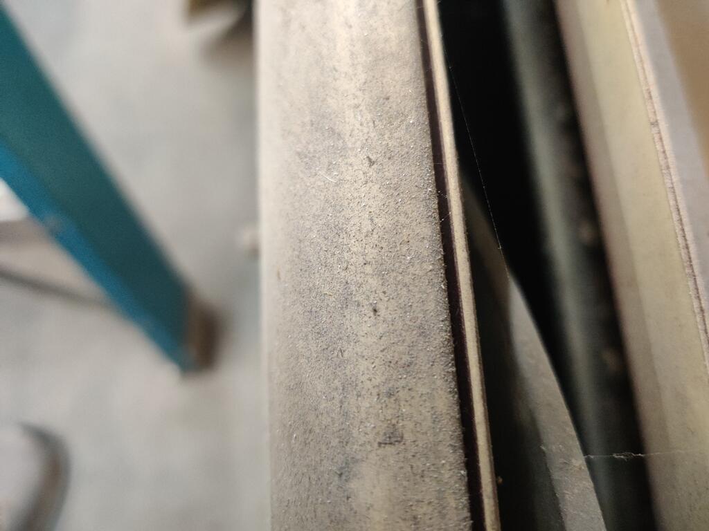
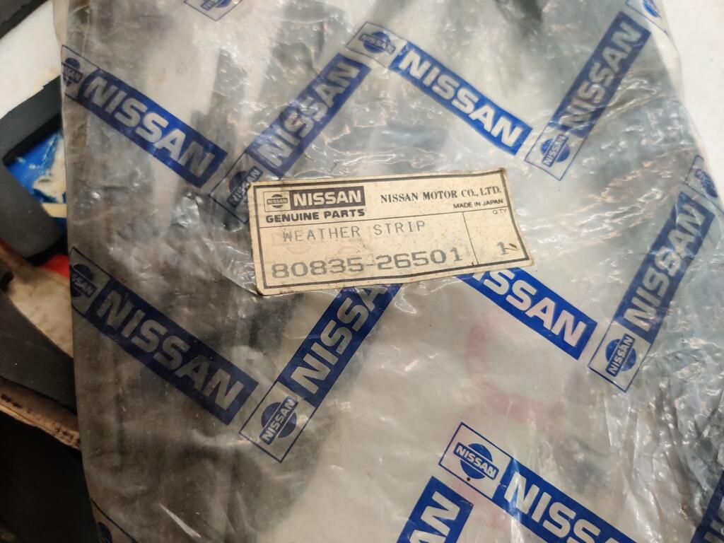
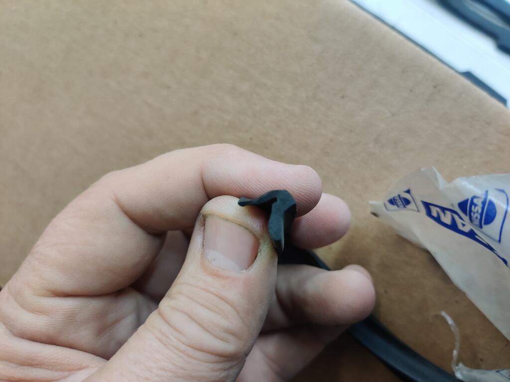
The first two pics are some 510 4 door outer door/window trim pieces. The second two are 510 2 door outer door/window trim pieces. The rubber looks to be the same shape to me for each of them. The next two pics show the groove on the inside top edge of the door where the inner rubber w/s goes. It is a simple u channel. The last three pictures are of NOS inner rubber weather strips for the 2 door. The front and rear doors of the wagon should use the same inner and outer w/s from a design standpoint, right?


-
-
-
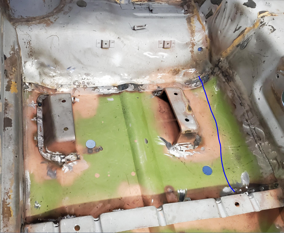
The inner rear seat mount looks to be in the wrong place to me. You may want to have them double check.
-
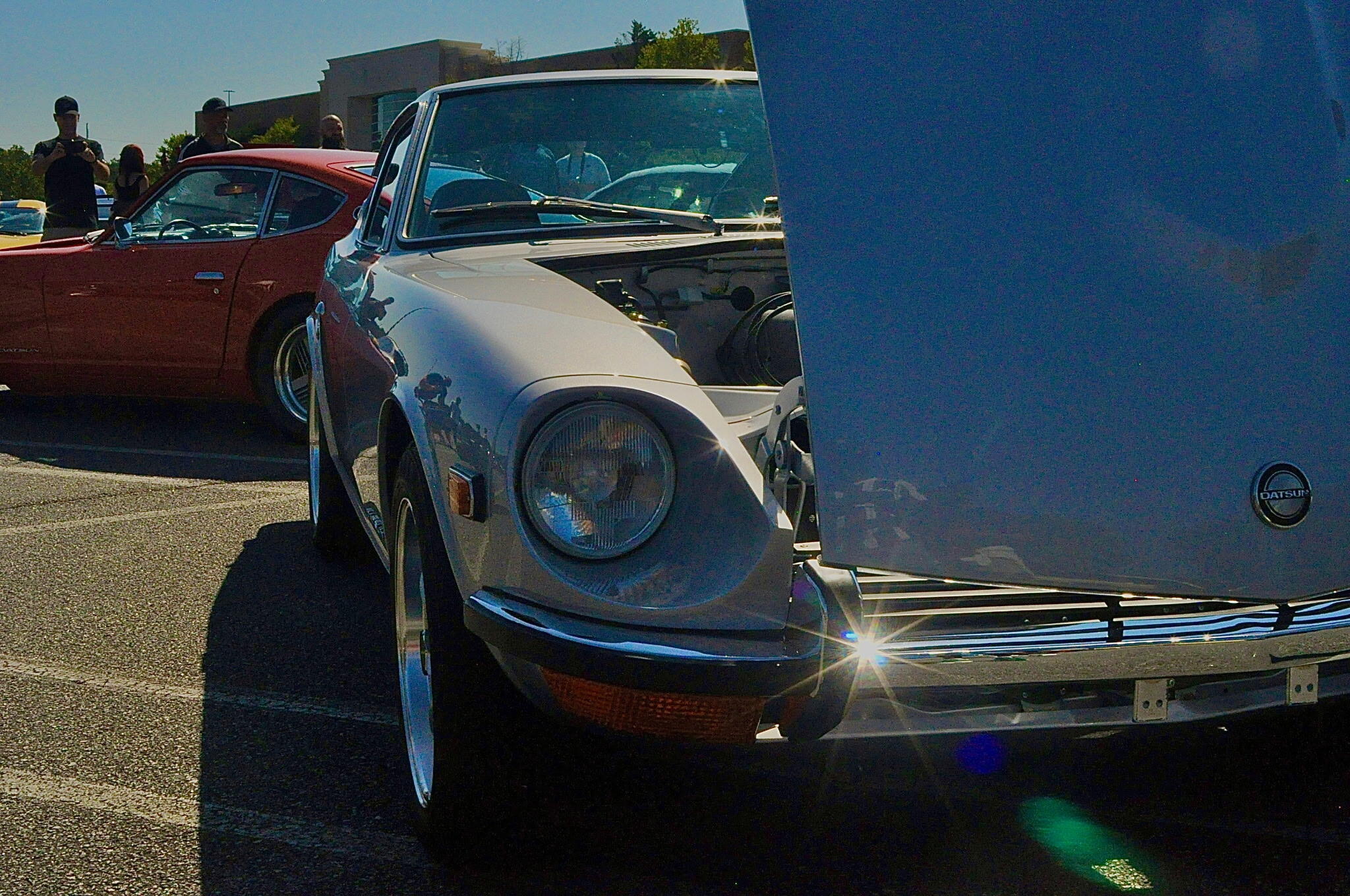
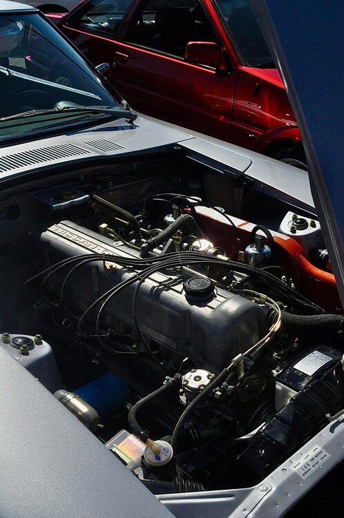
I took the car to Caffeine and Octane on 9/7. While there, one of the attendees offered to take some pics of my recently restored 1971 Datsun 240Z. Looks to me like she used some kind of lens filter. Nice of her to send them along to me.
.thumb.jpg.5773de9e8b4fb1e6e8ae94ad9ca5638e.jpg)
.thumb.jpg.0e15ff6d68903030860de7e52c077255.jpg)
.thumb.jpg.d2bd9602f29cc4bd2e07e82ca8b5005c.jpg)
.thumb.jpg.c9c2b6eeca68b6a00fd82c717d6ddc83.jpg)
.thumb.jpg.2266c5e8920524521450406020fb6aa6.jpg)
.thumb.jpg.b054fec78b2be911938a6cf18f7c7c10.jpg)

-
I think there are a lot of signals that the economy is weakening. To me, this is another of a great many.
-
Adhesive type matters. I have found contact adhesive available at local stores isn't good enough for high heat (automotive) applications. With interior temperatures going well north of 100 degrees repeatedly, it let's go. This stuff does not. It is only available by the gallon, and has a relatively short shelf life (a year or so), but I find it to be amazing, and crucial for any adhesive application in our cars.

-
Here is a post showing a bit about what I did to redo mine: https://www.classiczcars.com/forums/topic/63087-restoration-of-bringatrailer-240z-hls30-35883/page/63/?&_rid=2858#findComment-663237. I can't find it now, but someone found a material that I thought may be a better choice. It may have been @Patcon. The rubber I used is very durable, but it is rubber sheet. I found it to be less "shapeable" than the original foam like material. If I had to do it again, I'd look for a very thin neoprene or more foam like material, as I think this material would folder around the edges of the flap better.
-
Yesterday and today, I spent some time working on the car again. I haven't been working on it much, as I have been working on my track Z some more instead, and I had tenants move out, so I have been spending some time over the last few weekends at a rental house doing things that needed attention. I am still hesitant to modify my SM spec SU needles. Taking a lessor path of resistance, I swapped out the 10W-30 oil for some 20W-50 to see what a difference that would make. What got me thinking about doing that was the "drop test" of the SU pistons. From fully up to fully dropped, there seemed to be almost no damping. So, I decided to try a change. Comparing/contrasting, the throttle response is not as lightning quick as it was. However, the lean condition on overrun is noticeably less. I think I like the 20W50 better overall. I might try 10W-40 as well to see about getting a bit better throttle response (for rev matching downshifts). If I am cruising and I snap the throttle fully open, the engine and car respond quickly - it accelerates nicely. So, maybe the 20W50 is fine. I don't know what to do regarding the SU dampers. They are original Nissan ones - probably original to the carbs on the car. The "barrels" seem to have wear, just judging by their appearance. The barrels have an OD of a little more than .346". I purchased an SU rebuild kit, which came with new needle and seats, and dampers recently. However, I didn't use either. I found the problem with the existing needle and seats. The rear one just needed to be polished inside to keep it from sticking as when it was machined, it was finished with a coarse finish. Also, the new dampers have a "longer throw" than the original ones - the sleeve portion of the damper has a longer amount of free movement. I didn't want to introduce that change, so I have held off on switching them out. Also, the new damper sticks do not have low and high marks for oil level like the original ones have. However, the barrels measure at, or just above .346", just like the "worn" originals. So, again, given all of these things, I didn't feel like installing them. At present, I have the mixture nuts turned out precisely 2.5 turns front and back. When warm, the AFR at idle is around 11.8. At cruise on flat road, the AFR is about 14.8. I still see AFR get lean if I try to accelerate a small or medium amount. This often happens when the road changes to a slight incline. AFR on a slight incline, trying to maintain the same speed tends to be in the high 15's and can reach low 16's. If I smash the throttle to the floor, I typically see AFRs in the 12.4 to 13 range. With the 10W-30 oil, on long instances of throttle shut deceleration (like from third to second - rev match, and then just decel in second with throttle shut), the AFR would climb up to 18s... or 19s even. With the 20W50, AFR will spike lean on throttle shut decel for an instant, but then AFR will return to normal range (13 to 14). Much less popping from the exhaust with 20W50. I need to do some data logging again so I am not just pulling these from memory. I haven't heard of anyone with Hitachi SU's changing the springs, but watching various Youtube videos, it seems like changing springs is pretty standard with tuning British SU's, and it is typically done before attempting to modify needles. It looks like order of march is springs, dampers, oil, then needles. I think I'd like to try some springs which are bit stiffer. And I'd like to try 10W-40 instead of 20W-50. Maybe I will do these things before I try to modify the needles.
-
What do you think it is worth currently - roughly?
-
Looks to me like nearly every part of that car was touched during a restoration. I would think, even with current valuations for 240z's being lower than their peak, this car would be worth more than $70k.
-
Just now looked at the pictures of this car. Uh, yeah... no. Nope. Much of the sellers description is inaccurate. Garrett
-
Do you know about the special site: search? It limits searches to just that one site. If not, try to paste this into a google search: chrome door trim site:classiczcars.com
-
No-no, I said "My 12/70 (16530) is black. And my 6/71 is orange/yellow."
-
My VIN is HLS3016530. I will double check my memory. It has been a long time since I put eyes on that switch.
-
My 12/70 is black. And my 6/71 is orange/yellow. Still a wide range there.
-
I am thinking there are not many restoration shops that focus on Z's these days. Impatient Creations is doing good quality work. I think they are very expensive. But, they do good work. Looks like they are 30 minutes from Birmingham. https://impatientcreationsinc.com/
-
Some options to investigate: https://upgarageusa.com/pages/nos-parts-we-have-instock-for-1969-1995-z-cars https://vintagerubber.com/datsun-240z-260z-front-bumper-guard-over-rider-strip-kit-69-72/ https://jdm-car-parts.com/products/front-bumper-over-rider-vertical-strip-set-for-datsun-240z I believe I have a spare set of aftermarket ones as well - I think of decent quality. Let me know if you would like to see some pics of them.
-
I am about to start on the task of adjusting the profile of my Hitachi SU needles (I have SM needles installed). I read this thread in preparation: https://www.classiczcars.com/forums/topic/59153-modified-su-carb-needles-for-l28/ @240260280 has detailed knowledge on the subject which is impressive! I wish I had the tools and knowledge to do what he knows should be done. Instead of measuring vacuum, etc. as referenced there, I am thinking about rigging up a camera to record a video of the piston movement under certain real world scenarios. For that recording, I am thinking of putting black marker lines on the piston that equate to the station positions on the needle. For the real world scenarios, I would like to record a series of various part throttle applications. I am hopeful that I can locate a specific range of the needle that will need to be modified. Very generally, I believe I have good AFRs at idle, and cruise (at 50 mph for example), and at wide open throttle. On the other hand, I have lean or very lean conditions at part throttle and during closed throttle deceleration (accompanied by popping in the exhaust). I will be making some more AFR reference runs before I attempt to modify the needles to confirm. But then, I am hoping to record the videos, and remove a miniscule amount of material from the "pick up" needle stations. The segment of the needle I need to modify should be confirmed by reviewing the video. Anyone have additional recommendations or thoughts?
-
Looks like I never finished this thread. I replaced the front yoke and took the propeller shaft to a local shop for balancing. It was there opinion that the shop that did the shortening of the prop shaft did not balance it. When I went to install the shaft into the transmission, the "slop" (the amount I could push the yoke radially) was a lot. As an estimate from looking, I'd say I could move the yoke in any direction about .020". So, that is about a mm of movement radially. It might have been a bit more than that. So, I decided to replace the bushing that is in the tail shaft of the transmission. Looking back on it, I think the bushing developed wear because of the driveshaft being out of balance for the first 500 or so miles I put on the car. I think that the bushing was sacrificial - meaning made of softer material than the yoke. Anyway, after putting the new bushing in (removal and reinstallation of the transmission was required), the new yoke was tight (no discernable movement at all radially). With everything back together, the vibration that caused me to start this thread is gone!


.jpg.3c3e8812cc5d8514867770e5bd57e0a3.jpg)
.jpg.ba4f6165bf10c2b48166c3f9ffb89958.jpg)
.jpg.29a011ccd9829e69d4e75b014bd48f5b.jpg)
.jpg.4724424978e368fd06734166d72d6d1d.jpg)
.jpg.f13785688b8c7329dacbe4e01518de5b.jpg)
.jpg.7505c934fa5dfd5da3fd123a1f147cc5.jpg)