jfa.series1
 Subscriber
-
Joined
-
Last visited
Everything posted by jfa.series1
-
 Success on both issues (well, almost perfect)! Removing the old voltage regulator and re-installing the adapter cured the ignition problem. Also, removing the temperature sensor and wire brushing the threads on the retaining nut seems to have cured the temperature gauge problem. Right now there is one remaining question: I am seeing about 1 needle width of discharge on the ammeter with the engine running. I am not seeing any movement on the needle when I increase revs. I have a new battery and it shows fully charged on my maintainer (charging light is off). Steve - I will try the voltage test you recommended. Should I remove the regulator adapter for this test? And yes, the oil pressure gauge works. Thanks, Jim
 -
Thanks for the feedback, looks like you guys have identifed one or both problems. Yes, I have a 280ZX alternator upgrade. I initially had the regulator replacement adapter in place but was seeing no charge on the ammeter and discharge for lights, turn signal, etc. I presumed the adapter was bad so I pulled it and installed the original regulator, getting a modest charge showing and small discharge for lights, etc. Looks like I must go back to the regulator replacement adapter. Not being too good at auto electrics, how do I determine if I am getting a charge with the new set-up? On the temp sensor, I may have used teflon tape or other thread sealant. I will pull it and give the lock nut threads a good cleaning. Steve - if I understand you correctly, I should be able to measure voltage between the sensor terminal and ground? Can I test this at any time? Engine hot or cold, running or not? Thanks, Jim
-
I have two problems, am presuming right now they are not connected. 1. Ignition switch - the engine will not stop running when I turn the ignition switch off. Some background: the car just had the rebuilt engine installed and when we went to fire it up, the ignition switch worked initially to start the engine, then gave up on the starter circuit after a couple of cycles. I used a jumper to the starter solenoid for subsequent starts. We also noticed the engine would not stop when the switch was turned off. I pulled the B/W wire on the coil to kill the engine. My diagnosis: worn out ignition switch. Got a new one and installed it today and the starter circuit works great, however the engine still will not stop when the switch is turned off. Resorting to the B/W wire solution. 2. Temp gauge - the gauge initially worked when we fired up the engine and for several run cycles after. I brought the car home and started it the next day - the temp gauge did not work, same result today. As part of the rebuild, it has a new temp sensor in the thermostat housing. The wire to the sensor is in good shape and it has a tight connection. Details on the car are in my signature. Thanks for any help. Jim
-
CW - +1 on SteveJ's comments. I suspect he lived here recently to have such details about the two local clubs. Yes, ZCoT seems to have more 350 and 370Z owners in the active ranks. The S30's are still out there, they just don't come out as often. Even so, the ZCoT bunch still very much appreciates the older cars. The Cowtown club is much more active in the S30 area I'm told. They are too far from my home for me to try and get active with them. I am close to wrapping up my resto effort. Give me a PM and we can talk about a get-together. A good friend in Plano has a very early '70 car and would probably also like to talk cars with you. Consider getting up to Cars & Coffee in Plano on the 1st Saturday to meet other Z owners. Jim
-
Here is the link to the online parts catalog for the steering wheel. The exploded view should give you a good picture of the parts layout. I used this to solve the very same problem. Jim http://www.carpartsmanual.com/datsunS30/DatsunFairladyZIndex/Steering/SteeringWheel/tabid/1748/Default.aspx
-
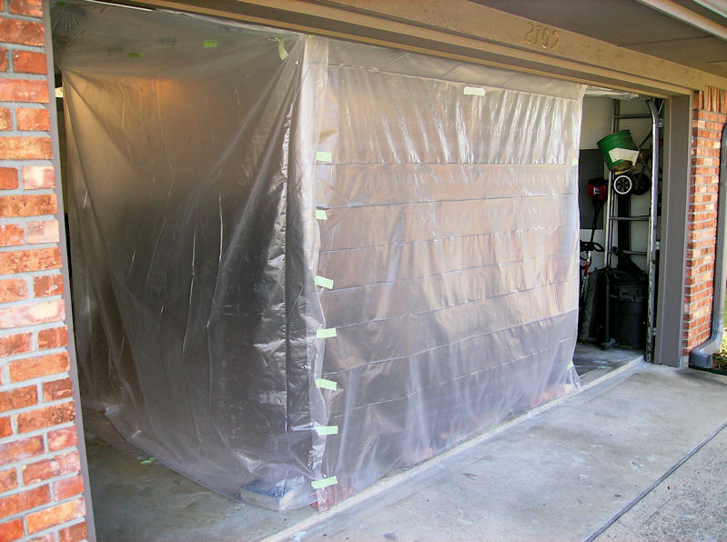
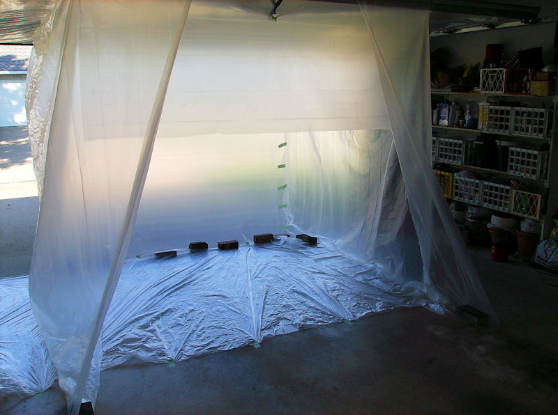
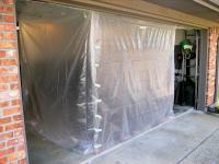
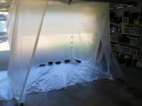
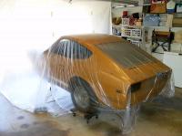
Been there, done that. +1 on all of Steve's great advice. Don't overlook eye protection - some disposable goggles is a must. Get a paper overall from somewhere such as Harbor Freight - with care you can use it a few times. This is the temporary booth I built to do my engine bay. A bit longer and I could have enclosed the entire car. Jim

-
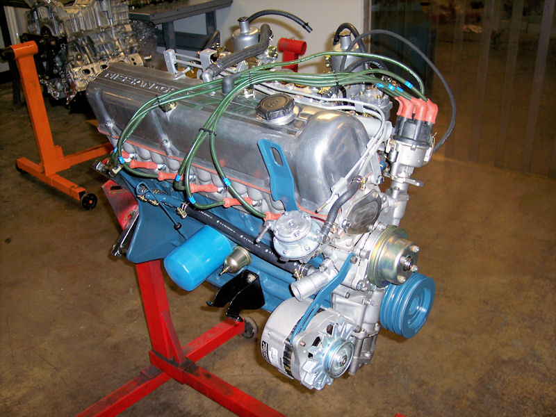
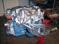
I finished "dressing" my engine in preparation for the upcoming install. Now to get it off the stand and onto blocks for the flywheel and new clutch kit, then to get the tranny bolted up. Fresh carbs are by our good friends at Z Therapy. Thanks Bruce! Jim

-
Here is a new sale announcement from MSA. http://www.thezstore.com/page/TZS/CTGY/wes-01a Jim
-
Look at the trade-offs of purchasing a new OE-type insulator pad vs. making one up yourself. The OE product has pretty high density plus all the correct cutouts for all the mounting points and thru-wall connections. A couple of cautions on bubble-foil: it will break down over time and it will easily crush anywhere a light pressure is applied. If you want to go the insulated foil route, look into closed-cell polyethylene foam with foil backing available in 1/4" thickness. It does not crush or breakdown, has a good R-factor and decibel reduction factor. I used this on the entire floorpan of my car AND the firewall before putting my original firewall pad back in - it was still in very good shape. I can provide a link for the foil if you have an interest. For a DIY pad, consider 1/2" high-density foam sheeting from a hobby or upholstery shop sandwiched between a foil coating. Or possibly 2-3 layers of the poly-foil I mentioned above glued together with a spray adhesive. Jim
-
Hey John - I know of at least one original Spook you won't be getting hold of! Good luck with your search. Jim
-
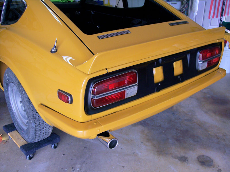
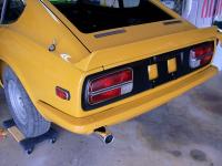
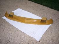
Agreed, not too many folks have seen the first BRE Spook. It was used only one year and did not gain popularity. So, that makes mine a bit of an oddity, perhaps a collectors item for a few. In addition to the Spook, the dealer also installed the BRE rear spoiler, show here also rehabbed and installed as part of my resto effort. I agree completely with the mention of handling differences at anything above 90 mph - and the Spook is effective at those speeds and above. [ATTACH=CONFIG]47044[/ATTACH] Jim
-
This is my BRE Mk 1 or Series 1 Spook that was already installed by the dealer when I bought my car 03/31/71. It has been fully re-habbed and will be back on the car soon. . It was the first design from BRE and used in 1970 competition only, to the best of my knowledge. Check the BRE archive pictures (link below) to see the 1970 car and the change on their 1971 cars to the design more commonly associated with the early BRE Spook. I suspect the first design did not provide adequate downforce, hence the redesign for 1971. http://www.bre2.net/mm5/merchant.mvc?Screen=CTGY&Store_Code=B&Category_Code=brearchivephotos240zs Jim
-
Hooray!!! Another Series 1 identified and into some caring hands. Enjoy The Ride! Be sure to share your VIN and more pictures with us. As others have said, go slowly and build a manageable plan for your work - a modest bite at a time. Get lots of pictures as you take things apart. Jim
-
If you are trying for something similar to the original, then you would be looking for a 5-piece kit, looped (not cut) carpet. Brian Rolfe at Seatz Mfg. has resto quality products for your interior, prices are typically no higher than MSA, BD, or others. http://www.seatzmfg.com/seatz/index.htm Jim
-
Banzai Motorworks has the end mount insulators for your front and rear bumpers. If you get the front ones, the thick part is positioned to the body. Jim http://www.zzxdatsun.com/catRubber.php
-
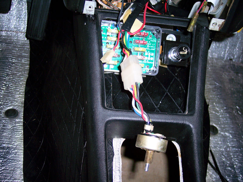
Not to get into a debate, but I think you may be looking at the power flow direction incorrectly. I don't see the power as coming from the harness to the connector. If that is the case, where is the harness getting its power? I see power flowing TO the switch from either the small connector OR the red wire. The switch then sends power thru the harness to the blower. Thus my argument above for an inflight engineering change to replace an inadequate power supply and ground TO the switch (the small connector) with a larger ga. wire and a shorter ground wire. BTW, the rear defroster switch wire connects to a pair of blade connectors in the bundle to the right of the console: green/blue (switch wire) to blue, red (switch wire) to red/black. Jim
-
Ok, our build dates are close enough together to have similar or the same parts. I think what we are seeing is another of the evolutionary changes during the early build cycle. My theory: the sub-harness started out with the small connector as the power source and ground. The wiring ga. was too light for the load so the single red wire (larger ga.) and the single black wire (larger ga. and a shorter ground length) were added to the harness as replacements. One look at the harness shows these to be after-thoughts, not well engineered into the original design. That is why the '71 Supplemental FSB diagram shows the original connector as a "ghost" and does not identify it - they did not want you to use it. Use the two added wires instead. I completely agree with you that if both sets are connected, a fuse or two will go, or even worse!!! When I pulled my dash, I did not disconnect the sub-harness, so my red wire and black wire remained attached as installed at the factory. That helps me explain why I did not tag the small connector - it was not attached to anything to tag as I broke various connections. My red wire is attached in the large bundle to the right of the console, I will take a look and get back to you with what I find. Jim
-
Coop - thanks. I will dive back in there and search for a male connector on the main harness. It has to be very close because of the limited reach from the switch mounting point. On the main power item, the FSM identifies a single red wire as providing the power, connection #55 on the diagram. I have that wire in place and connected to the main harness, as well as #56, the ground connected to the dash frame. Is it possible there is a difference in our two sub-harnesses? What is your build date? Jim
-
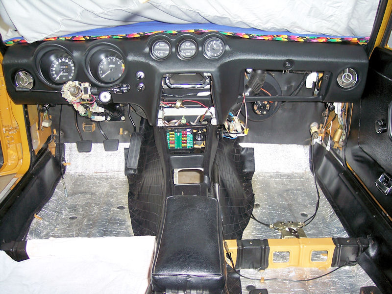
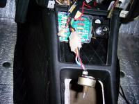
The antenna switch is also accounted for. It too, is in the right side bundle. No cigar yet. I just wrapped up all the dash area electrical connections this afternoon, including the steering column. No orphan male connectors with two wires anywhere in the area. I suspect this one is a factory orphan. Here is a picture of it and my almost complete dash install, this may stir someone's recollection. Heck, if we get enough guesses, we may find a good use for it. :bulb: Jim

-
Arne - I had the defroster switch wire marked and it is back together. It is part of the large bundle with the vinyl wrapper on the right side of the console. Jim
-
The intermediate wiring harness for the blower switch has a small connector that is not identified in the Supplemental FSM. The connector has provisions for 3 pins but has only two wires - red and blue. I'm referring to page 26 of the '71 Supplemental FSM. As I reconnect my electrical system, I'm trying to ensure there are no orphans. I did not mark this connector back when I tore it down, so it may have been unused at that time. Any ideas? Thanks, Jim
-
A variation on the kill switch is a well-hidden kill fuse. My brother-in-law has done this to all of his project cars. As mentioned above, the ignition-to-starter solenoid wire (black/white on my car) is a good candidate - not all cars have an electric fuel pump. Identify a place in the car to well conceal a fuse receptacle that you can still acess conveniently. Not an obvious spot like the glove box or ash tray. Don't share the fuse location with others. Locate the ignition wire inside the car, cut and splice in a similar ga. wire pair to your secret location. Solder in the fuse receiver wires, don't use quick disconnects or butt connectors that could allow the fuse to be easily bypassed if located. Then it is only a matter of pulling the fuse whenever you park the car. Jim
-
I recently had a return/exchange with MSA, it was handled very well. They also gave me a store credit for my return shipping cost. As Arne says, give them a chance to correct the problem. It is unreasonable to expect MSA or any other store to inspect every part they stock. Jim
-
Let the fun begin!!! Congratulations on getting possession of your new obsession (or perhaps it is the other way around). Jim
-
RockAuto is a great source for your parts, excellent service and super prices. Google for a RockAuto discount, you will always find a 5% code active. MSA provides a typical 10% discount for club members on many but not all parts, never on sale items. I am registered to Carl Beck's Internet Z Car Club as well as belonging to my local group, Z Club of Texas. This got me into discount status. Establish a logon with MSA then contact their customer service with your club affilation details. If accepted, they will update your account so that when you log in, all pricing will show applicable discounts. Jim