


Zed Head
Community Member
-
Joined
-
Last visited
Everything posted by Zed Head
-
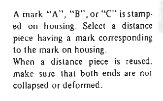
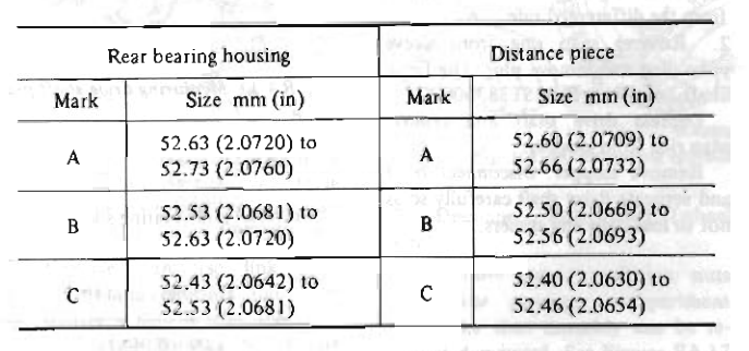
The bearing pressing has been discussed off and on around the internet. The procedure is counter to normal but it's what Nissan says to do. The question would be "how much force is necessary to get the bearing races seated?" The final torque value is only on the inner race and distance piece, not the balls and races. I haven't done one so don't know how hard it is to push the races in during installation.
-
I didn't really think that you would find anything but it was worth a look. It's not clear how the ignition modules fail, but they do at a pretty regular rate. If it was mine I would take it for a drive and see if the problem repeats. Take extra care to note what happens when it does. You only have this one incident to guess about. Stop immediately when it happens and let things cool down for a few seconds. Restart and see what happens. You need more data.
-
That would keep the fuel in the line at radiator temperature while the car sat. Probably around 150 F, guessing. Not good. Besides that, if the problem is after the car sits, it's most likely the float bowls boiling dry. Do you have an electric fuel pump or mechanical?
-
The key part of the "failing ignition module" statement is the "ing". It's not failed, it's failing. The heat generated from higher RPM must cause something to stop operating correctly, causing too many sparks. At least, that's how mine seemed to be failing. So, testing it cold won't show the problem. It would be an intermittent problem. Post a picture of the circuit board inside the module if you want to give it an ocular assessment. Maybe somebody will see a burnt trace or leaking capacitor. Any visible signs would be on the circuit board.
-
They can apparently get squashed from hard usage or accidents.
-
That's a lot of weld. Don't forget to measure your distance pieces.
-
The Parts Manual shows four variations. Might be a clue. https://www.carpartsmanual.com/datsun/Z-1969-1978/engine-280z/e-f-i/air-flow
-
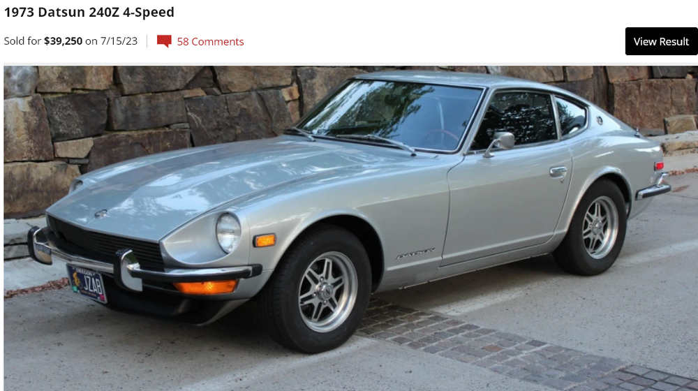
Pretty good price for a 73. Minor modifications. $39,250. https://bringatrailer.com/listing/1973-datsun-240z-208/
-
Could you describe the MSD ignition system? Your 240Z came with points and a ballast resistor. Are you using the points to run an MSD ignition box?
-
Are you going to weld that yourself? Curious about the materials also, are they similar steels? That is a high stress area, and you'll have all of the force passing through the weld. You'll want a proper match of metals and welding wire and weld depth. It's on the inside so you'll only lose motive force if it breaks, at least no wheels will fall off. You're too deep in to it now but did you ever confirm that you need that extra distance? I spent a few hours building an adapter for the other ZX 3x2 CV axles so I get the urge to fabricate. I never used it but it was fun to build.
-
You work in Arizona where it never gets cold. Did you or your son ever break a windshield? You said you replaced dozens but didn't say that you never broke one. My first experience removing a windshield was in a wrecking yard. The owner was gone and his wife told me and my friend that we should wait but I told her that we could do it. It was about 35 F. A small tendril of adhesive was still attached (GM used a rope of sticky tar-like adhesive for windshield installs. Nasty stuff) as we tried to lift it out and it cracked. We left, I didn't pay for it (cause I was a punk kid), and the owner started calling me "Easy Money" after that. In the long run I paid him back by giving him a 66 GTO (the same one that I was getting the windshield for) after I wrecked it, and his son a 55 Chevy pickup truck after the axle bearing went bad. The statement was, basically, that old windshields, especially those with chips, are more prone to cracking than new ones. Just because you guys were careful enough to get it done doesn't mean the statement is not true. Anybody who's watched a chip grow in to a crack and spread across the windshield should know. Tell some stories about how to get it done. Heating the adhesive helps, a warm day helps, make sure that every scrap of adhesive is cut free (a PO might have tried to seal a windshield leak in the past). Stuff like that. Interesting though that by the statement it broke during installation. So the BS calling ia about the wrong part as are my suggestions above.
-
I don't know, that Amazon link looked new to me. Pretty interesting. Hope my memory is not fading...
-
The polymer adhesive layer probably loses flexibility over time. That could change the forces on the two glass layers. And besides the visible chips the whole surface of the glass is probably etched to a certain degree after years of road debris and acid rain and washings. A vast array of stress risers. As a whole, an old windshield would/should be more prone to cracking than a new one. One more opinion. Did @zKars ever get his windshield? He said he would post back in that other thread.
-
Interesting drama on BAT. Arizona retitling. https://bringatrailer.com/listing/1977-datsun-280z-98/#comments-anchor
-
Here's another. No need to go to the specialty shops, I think. https://www.kitsapvalueglass.com/
-
These guys look promising. They're in the automotive heartland (of the past). https://koolkatzautoglass.com/products/windshield-fits-nissan-1975-1978-280z-1970-1973-240z-1974-260z-oem-new https://koolkatzautoglass.com/pages/about-us https://en.wikipedia.org/wiki/Area_code_440
-
Here's a variation, maybe even the inspiration for (or vice-versa), of the Silvermine adapter flange. It doesn't have the 4 mm problem. Lots of other good details in the thread too. And he was selling them. Doesn't look like he's visited Hybridz since late May though. https://forums.hybridz.org/topic/128943-z31t-axle-swap-can-fit/#comment-1204163 https://forums.hybridz.org/topic/128951-fs-z31t-axle-adapter-flanges-for-s30-r200-slim-design/#comments
-
My point was just that I didn't know when "Silvermine" was introduced to the work. It appeared with no previous mention. They have a lot of stuff. Couldn't tell what you were working with. https://www.silverminemotors.com/collections/datsun-280z
-
JMortensen had a good suggestion over on Hybridz, years ago. He assembles his suspension without the spring and runs the hub through its full travel by hand. Might be worth doing to verify the problem Also note that for a reason that has not been quantified, the 240Z's tend to have binding problems with the factory u-joint shafts after an R200 swap. The only rational reason would be that the 240Z flanges project in toward the center of the car (less distance between flanges left to right) than on the 280Z's. In short, it might be worth confirming it's a 280Z problem and not just a 240Z problem. On the nut - you could tack it down with a MIG welder if you have one. It's easily accessible to grind off in the future. 200,000 miles from now.
-
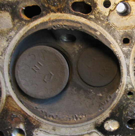
Those dimples around the edge here could be detonation damage or foreign object. The damage looks the same, but it's only at the edges in your case where the detonations would be. Not a big deal, just an observation. What's the top of that piston look like?
-
Sorry, I misunderstood. You're saying it's a Trakmotive problem. But don't the Trakmotive axles come with the Silvermine kit? I don't know.
-
Hastings implies that their rings are not meant to be filed to fit unless they are racing rings. https://www.hastingspistonrings.com/tech-tips-faqs/
-
If the supplier doesn't know then they'll just keep disappointing customers. One of those weird ironies where exposing flaws helps the company. You've already said, in essence, that the Silvermine product(s) (undefined) has/have problems. Sorry, it's just the logic of the situation. Not sure that "on notice" is the correct term here. You might find that it really was you, not them. But, without the story it looks like them.
-
Can't you just post the details here? We want to know too...
-
Not sure if you mentioned the Silvermine package in one of your threads (it's hard to to follow along when you start a new thread for each sub-project), but if it's one with adjustable control arms you could also widen the track to get clearance for the axles. That's what some people do. And, since I'm here, might as well say that the u-joint halfshafts are actually pretty strong, Lots of guys run them with high HP Chevy small blocks. The CV axle swap was a neat idea when people were using Nissan CV axles but I'm not so sure that aftermarket Trakmotive axles are better than Nissan u-joint halfshafts. Not trying to be a buzzkill, just pointing out the aftermarket problem. That is also something to keep in mind if you run the u-joint shafts for a while. New aftermarket u-joints are probably not better than used Nissan u-joints. Anyway, looks like fun.


