


I decided to add a Vintage Air mini system to my S30 restomod build. The intended engine is an L28 stroker. The engine is currently on a stand.
While many Classic Zcar posts have discussed various aspects of installing an A/C system into an S30 chassis, none, to my knowledge, have ever given details regarding the fabrication of a bracket to fit on the lower front left side of an L6 engine and hold a Sanden compressor in the proper orientation. This post is intended to rectify that information void. The most detailed post that I could find on Classic Zcar was created by Freez74 (Gary) in December, 2020 and I consulted him on a few matters before I started my fabrication efforts.
Both Gary and I started with the universal Sanden compressor mounting brackets available from Vintage Air. He got his from Summit Racing in Talmadge, Ohio. I bought mine from JEGS for $45 as I live close by to its HQ in Delaware, Ohio and can easily get to its retail store in Columbus. So, I can save on shipping costs. Hooray for me.

As you can see, the brackets have a nice shape to them and appear to offer a lot of adjustability for keeping the drive belt tight. The brackets are laser cut from ¼-inch steel and there’s a lot of metal at the tail end to play with so as to get proper distancing of the compressor both from the engine and from the surrounding bay walls and other bits like the steering rack.
Gary said he used 3/16” steel plate to make his base plate to which he welded his brackets after cutting off a sufficient amount of excess steel. He said that the steel base plate flexed a little but that probably isn’t a big issue as it’s firmly bolted to the block. He also decided to have his brackets go underneath the compressor. This approach places the compressor higher up along the block and, because of this, it is close to the intake and exhaust manifolds. This necessitated he orient the compressor so that its intake and outlet ports are in a horizontal position.

I decided to reverse the bracket orientation so that the compressor ports could be in a more vertical orientation and the adjusting slot on the rear bracket was in an easily accessible position on top.
I had a problem, however: the engine is not in the car, it’s on a stand. Thus, I had to figure out how much metal to cut off the brackets so that the compressor would clear the left frame rail in the engine bay as well as the intake and exhaust manifolds to not present problems with hooking up the E-Z Clip fittings that I decided to use for my A/C system. Here’s what I did.
First, I had to decide how big a base plate I needed to have. Gary did not have any dimensions that he could solidly recall so I was on my own for that, although he did tell me that his plate was about 7-1/4” by 5-1/2”. In looking at the mounting locations on the engine block, I decided that starting with a 6”x7” plate would be appropriate. I got some scrap ¼” steel from a local steel fabrication shop and used a horizontal band saw to cut it to shape.
I then had to decide where to put the holes for the M10-1.5 bolts that go into the block. Gary said he traced the block holes on paper and then transferred the locations to his base plate. I was able to easily measure the hole distances. But I also had to decide how far forward to place the base plate. What to do? What to do?
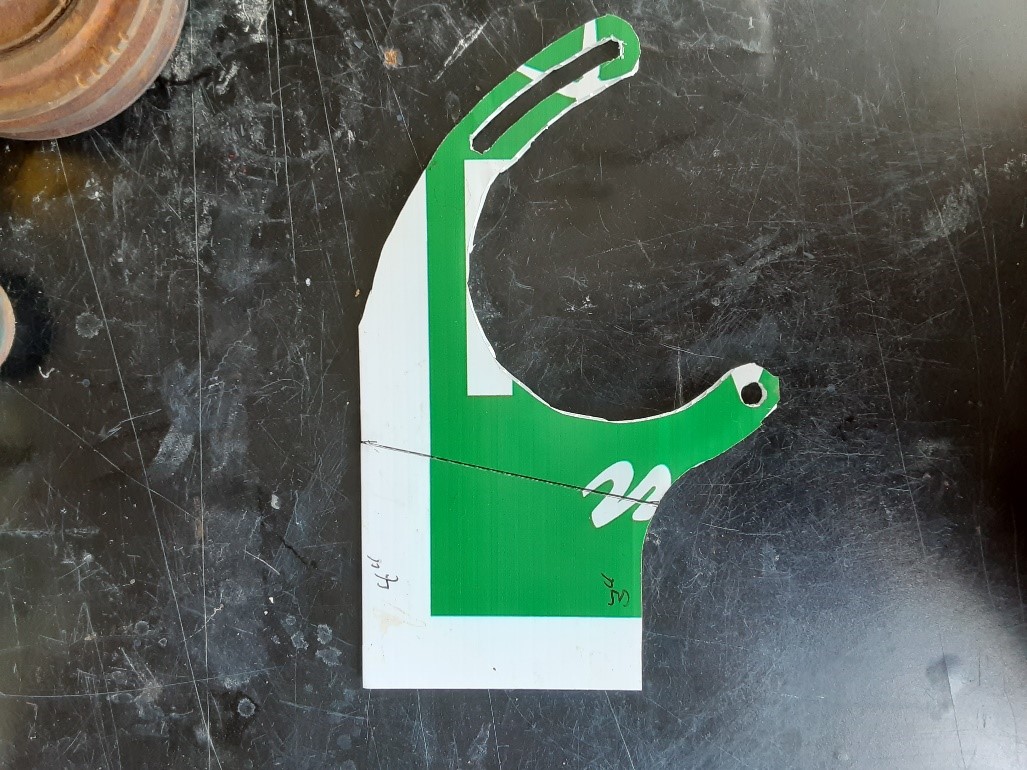
I decided to mock up both the base place and the brackets using some old political yard sign stock – the kind that’s made from a corrugated plastic. Fairly quickly, I determined that a good placement had the rear bolt holes ½” from the rear edge of the base plate. I also determined that the topmost holes were fine at ½” from the top edge of the plate. From eyeballing the mockup position compared to the crank pulley, this gave me plenty of space at the front of the plate on which to locate the front bracket.

I drilled 27/64” holes (10.72 mm) at my four locations. Because they were larger than what was absolutely necessary for the 10 mm bolts, this would give me the “slop” I might need to get things aligned. Below are the dimensions that I used. Sorry about the tilted arrows – Word is not the best thing for making graphics. I have since determined that the 6” base plate dimension could just as easily be 5-1/4” so take your choice. I’ll probably cut my plate down now that I know.

And here is what it looked like in real life.

Now that I had the base plate drilled, it was time to determine how much metal to cut off the bracket tails. Here is where making mockups became very important. I made several mockups of the brackets as received.
Using an adjustable-height chair and some wedges, I was able to support the compressor bolted to the mockup brackets and hold it in position next to the engine on the base plate. I had previously attached an engine cross-member to the block and tilted it the requisite 12 degrees so the X-member was horizontal and level. I could then visualize where the frame rail would be located.
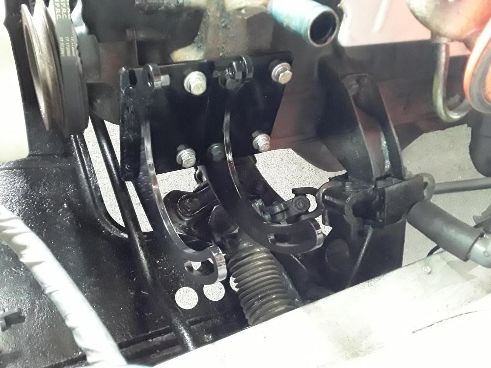
After a few iterations, I determined where to make my cuts. I chose to cut a diagonal line with an end point 4” in from the tail edge on the “long” side of the bracket and 3” in from that same edge on the “short” side. You can see the line marked in the picture above. The position of the compressor with this revised bracket is shown below. Note how the two ports are almost vertical and I still have room to adjust the drive belt tension.

Looking at it from directly above, you can see there is adequate clearance from the imaginary frame rail where its inner wall would be along the yellow line that I’ve drawn on the photo where the engine pylon rises from the X-member.

So, with that settled, the brackets were cut and the whole assembly once again test fitted.
 Now
Now

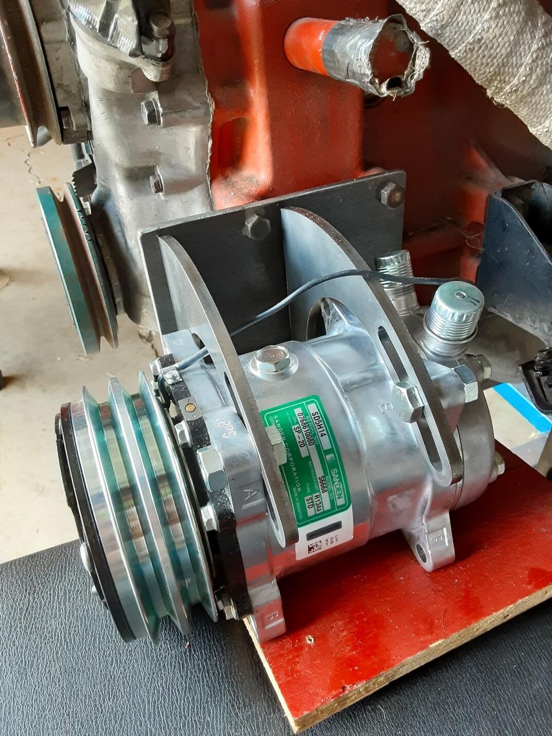
Now came determining the actual location of the brackets on the base plate. I aligned the grooves of the single-groove crank pulley, the water pump pulley and the rearmost groove on the compressor drive pulley to arrive at this positioning. I should mention that I have a dual groove crank pulley that will be used in the final installation and its grooves align with the double grooves on the compressor. See the final photo in the article. The front grooves of each pulley will be used to drive the compressor.
The distance from the leading edge of the base plate to the front wall of the forward bracket is 3/8” (about 10 mm). I marked the location and welded the bracket into place. The compressor itself then dictated the location of the rear bracket.

Finishing up the welds gave me my final piece. I’ll dress it up and paint it so that my under-developed welding skills will be less evident; i.e., embarrassing, and I’ll be ready for next year’s warm weather.

I hope this article will be of some assistance to folks who will want to install a Sanden compressor. As a retired research scientist, I know that we stand on the work of those who came before us and hope to provide a good base for those who come after us.
I am happy to have a conversation with anyone about my installation.


Recommended Comments
There are no comments to display.
Create an account or sign in to comment
You need to be a member in order to leave a comment
Create an account
Sign up for a new account in our community. It's easy!
Register a new accountSign in
Already have an account? Sign in here.
Sign In Now