bacarl
-
Posts
149 -
Joined
-
Last visited
bacarl's Achievements
")


-
Holy crap. You're absolutely right. I didn't realize they grounded through the case, although now that I know that I don't know how else they'd ground, since they only have one power wire. I guess the sockets just popped out of the backs of the gauges one by one (to Zed Head's point about flaky sockets) until only the tach was left to light up. I put the blinkers and one of the speedo bulbs back in and lo and behold they work fine. Learn something every day. I do have a multimeter and I was testing the sockets, but since I didn't know how the ground worked I wasn't seeing any voltage. Once I grounded the meter to metal elsewhere on the car I saw the expected voltage at the socket. Thanks so much guys. edit: I am still curious about the random red/blue female connector hanging out by the blower motor...
-
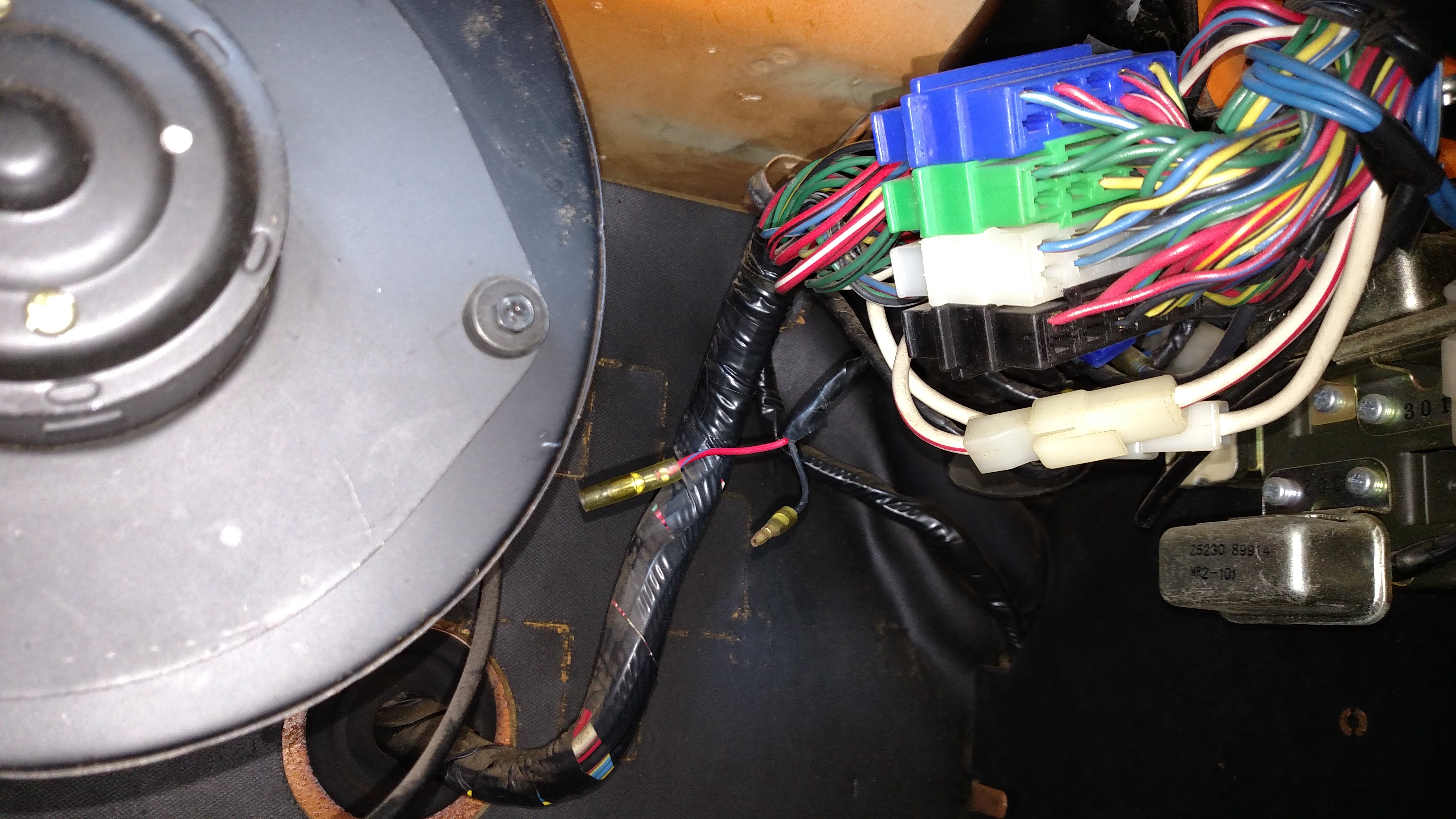
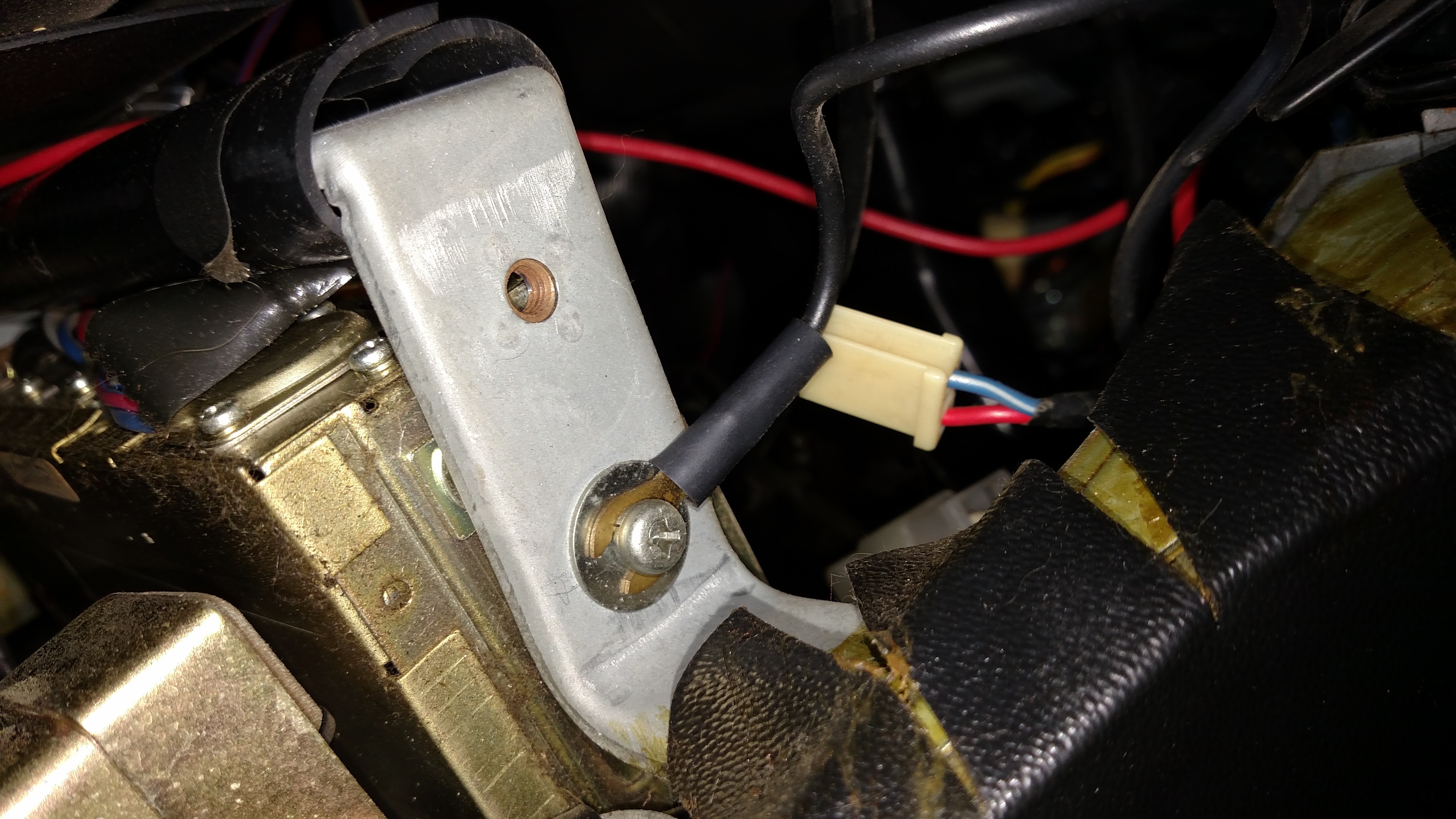
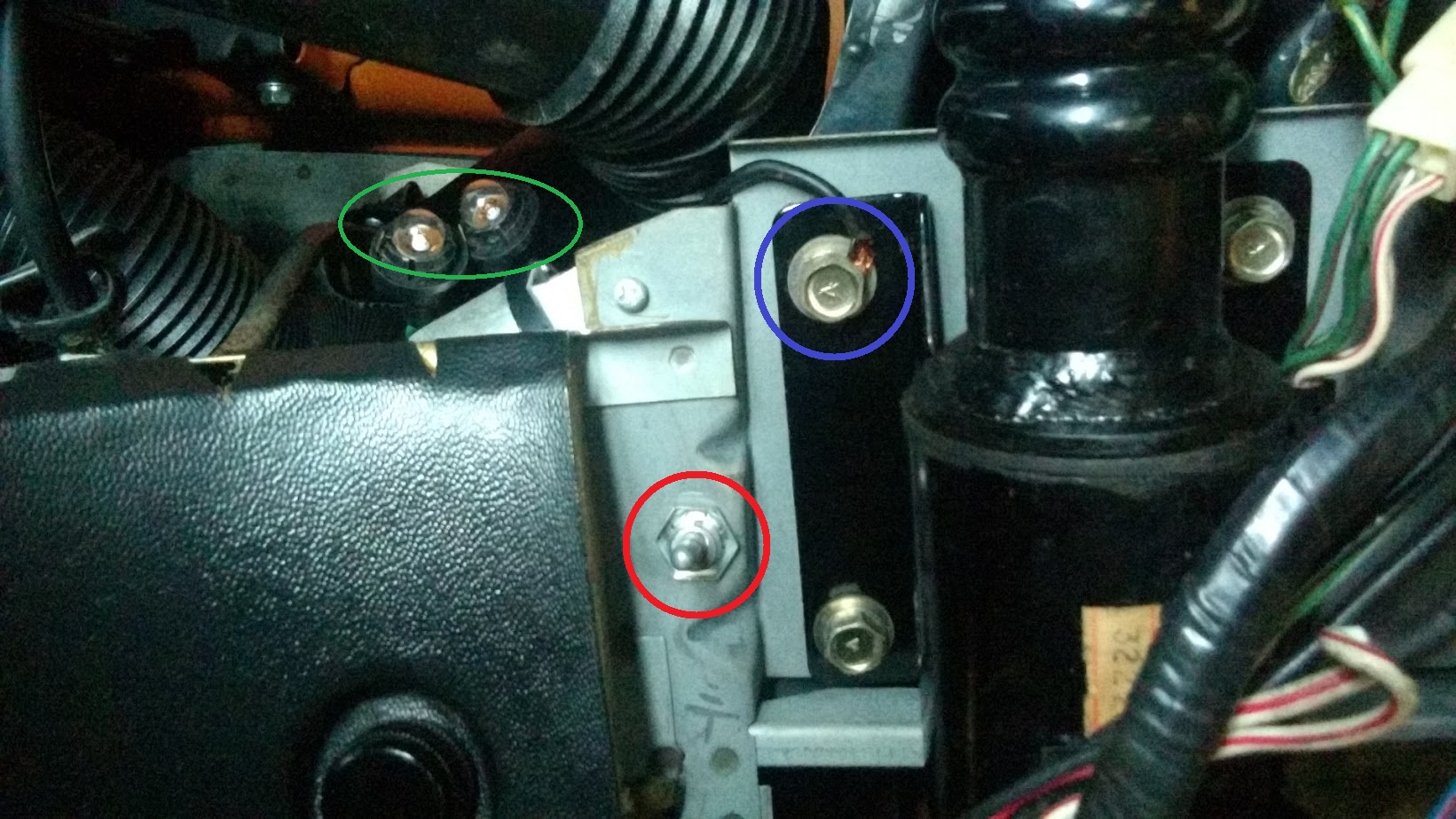
Hey guys, sorry to post on a topic that has probably been discussed, I'm still in the process of searching for info. I haven't found anything relevant yet so I'm posting up in the meantime to see if anyone has any insight. Problem: gauges do not light up. Namely the speedo and the triple gauges (fuel etc). Everything else lights up including the tach, map light, radio/console, etc. Except, while trying to fix this issue, my interior turn signals quit working too. The exterior amber lights still flash, but the two small indicator bulbs inside the tach do not. I've put eyes on the blinker bulbs and three bulbs behind the dash (I think there is only one per gauge, right?) and they aren't burned out. All fuses are good. Complicating matters: the PO installed two kill switches that I thought might be causing problems. One is very difficult to reach and I'm not sure what it's wired into. The other was spliced into the hot-at-all-times, red/white headlight circuit underneath the steering column. I removed this switch and repaired the wiring; the headlights do work now. The gauge bulbs are all on a red/blue circuit. Over on the passenger side under the glovebox I found a red/blue female bullet connector unplugged, but I can't find anything to plug it into. Here's a pic. Incidentally, there's also an unplugged black male bullet connector right next to the female. I foolishly tried plugging these together which blew the 10A fuse on the bulb circuit. I've replaced the fuse. Can anyone check to see what this red/blue is supposed to be connected to? I found another connector unplugged under the steering column, it appears to have a red and a blue/white wire. I haven't tracked this one down on the wiring diagram yet. Any idea if it's supposed to have a mating connector? It's behind the radio, kind of near the driver's right knee. And lastly here's a pic of the remaining kill switch (red). It has a black wire that's smashed under a nearby bolt (blue). You can also see the two blinker bulbs hanging down (green). This is taken from under the steering column looking straight up. The red/white wire in the lower right corner is where the second switch used to be wired in. So questions are: Is the red/blue female bullet connector supposed to be connected to something under the glovebox? Is the red & blue/white two-wire connector supposed to be connected to something under the steering column? What could have caused my blinkers to suddenly stop working - are they somehow related to the gauge lighting? Thank you very very much for any help!! PS the car runs and drives normally, the blinker indicators used to work just fine, and I've gotten the gauge lights to flicker in the past but lately they have been completely off all the time. The wiring is stock AFAIK except for the kill switches, and the PO also disabled the seatbelt light/buzzer. I read in another post that the rheostat might be bad, but it seems to work fine: the tach light dims/brightens normally.

-
Old thread but it's a good one... I doubt Manny will read this three years later but if anyone can comment I'd appreciate it. After you removed the push rod was the seal still in good shape and reusable? Is there any place to source a new seal if necessary? I didn't see anything from MSA or from a generic Google search. Any tips in general regarding removing the push rod or is it pretty self explanatory once I get in there? Thanks guys.
-
What was ultimately causing the backfire?
-
Caretaking and progress updates for my '73
bacarl replied to bacarl's topic in Introductions and Rides
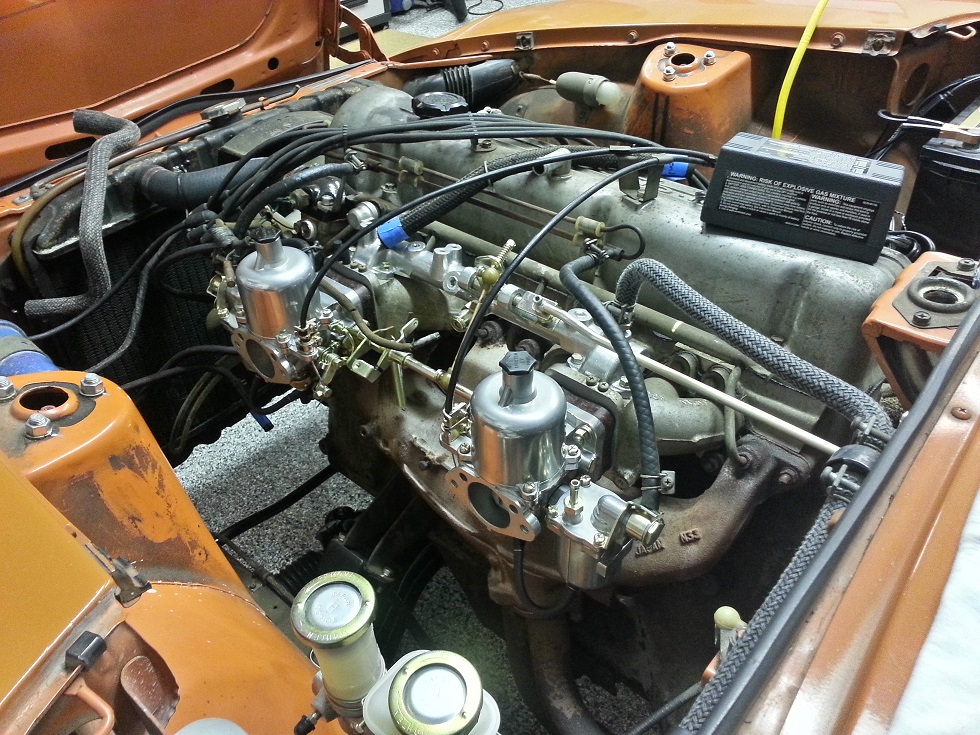
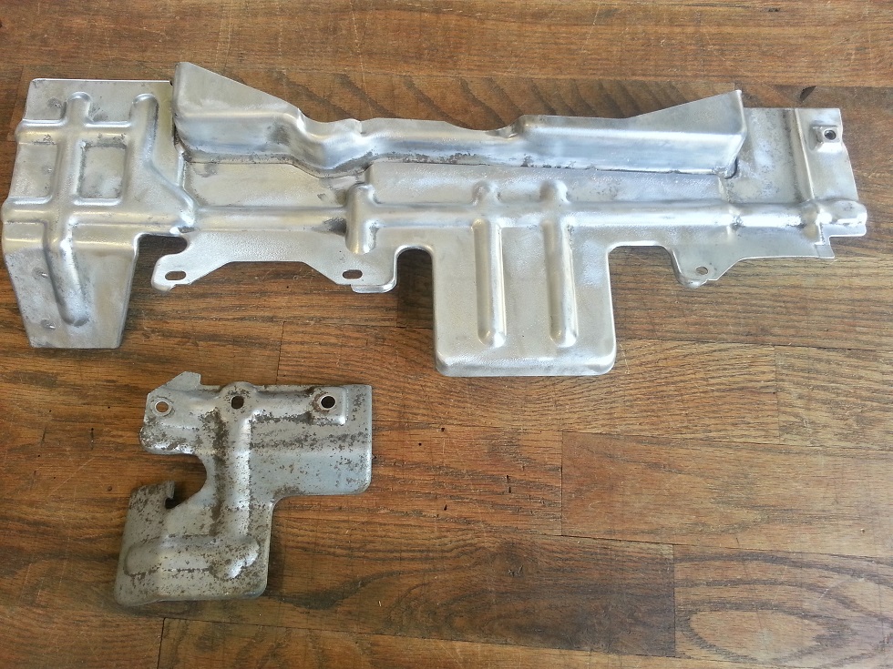
Removing the flat tops was by far the trickiest part of the project. In comparison, installing the SUs was cake. ZTherapy's kit is very comprehensive and includes everything from the correct carb insulators with longer studs, to the right length throttle linkage. And of course all the awesome refinished bits and plated hardware that everyone is used to seeing. I have to give ZTherapy credit and an extra thank you here because they actually sent me an old '72-ish air cleaner from their stash for free. My original square-mouthed air cleaner would not have been compatible with the round-mouthed SUs. So having gotten the flat tops removed I set about bolting on the new SUs and balance tube and hooking up fuel and chokes - that was it! From this to this I did spend some time checking/adjusting the float levels on the SUs, so hopefully I'll avoid issues there once the system is full of fuel. My float bowls haven't got a drain plug so I don't think I can do the clear hose sight glass trick to check float level. I adjusted both floats to start shutting off fuel flow at the ZTherapy-recommended 14mm/0.55" below the float bowl lid. In reality it takes several millimeters of float travel to shut off fuel flow completely, but I got both floats pretty even; flow restriction begins around 16mm and is almost completely shut off by 13mm float height. I was making these adjustments with the float bowl lids off the carbs and blowing through the fuel inlets. This way I could move the floats up and down and check the height with calipers. The heat shields are still missing in the pic above. I was planning to clean them up and paint them but I no longer have access to the sandblaster I used during my suspension refresh. I started wire wheeling the shield instead, which didn't work very well. It seemed to be melting the original galvanization layer instead of removing it. At that point I wasn't sure if the zinc coating would still prevent corrosion, so I decided to get the shields replated. A local company charges $75 for a minimum order which seemed reasonable; I just wish there were more silver zinc parts on this car I could have added to my order! I'm sure I could have added several more pieces and stayed under the $75 minimum. I haven't got the shields back yet but here's a before pic, with the larger shield partially wire wheeled. I'll take a few more photos tonight and add another update. I'm almost ready to start the car, just need to put coolant back in. When the time comes I might try using a small syringe to add fuel directly to the float bowls through the vent tubes to speed up the starting process.
-
Caretaking and progress updates for my '73
bacarl replied to bacarl's topic in Introductions and Rides
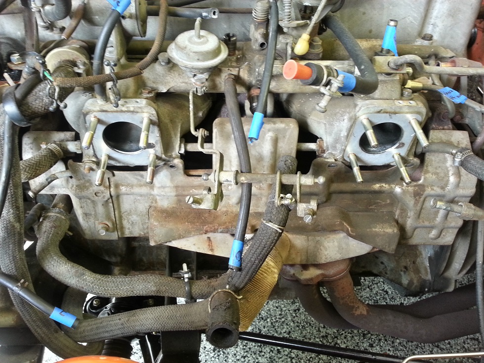
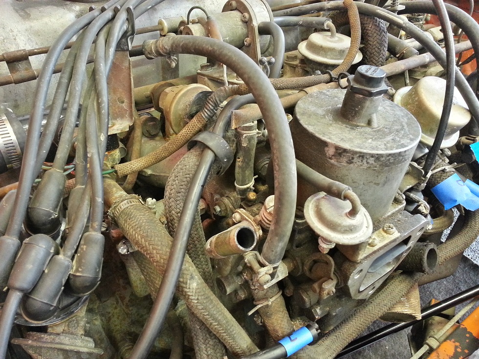
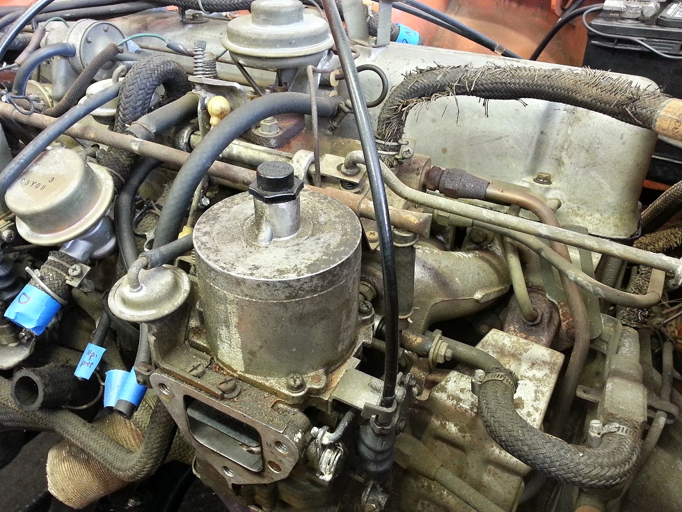
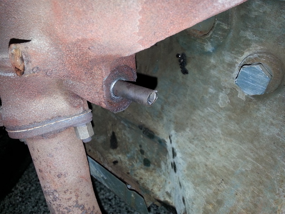
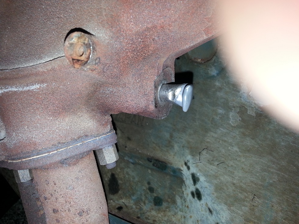
I did very little with the Z over the winter. I got married last year and between that, work, travel, and old fashioned laziness, I didn't spend as much time with the car as the previous winter with my suspension rebuild. Instead, I've been taking advantage of this summer's pleasant temps (you know: when we're supposed to be out driving our cars) to work on my next project, which has been to swap my flat top carburetors to SUs. I debated for a long time about whether I wanted to do this or not. The engine was totally stock, and a '73 equipped with flat tops, air pump, and all the original factory gear is fairly rare. But in the end I decided I wanted the day-to-day simplicity, reliability and performance that an SU set up could provide. My original plan was to tune up the flat tops properly and see how they ran in good shape. But tearing them down was a daunting prospect by itself, and I was worried that after I'd completed all that, I still wouldn't be thrilled with their performance. They're a very different animal than the SUs and since I have no experience with carburetors in general, I wanted the simplest hardware possible which has the most resources available to try and get the car running properly. So with a strange kind of vindictive pleasure mixed with remorse I started disconnecting the many hoses and lines to begin removing the flat tops. Here's where I started. These lines carry coolant through the balance tube and carbs, vacuum to various diaphragms and actuators, fresh air to the exhaust manifold, exhaust gases to the intake, etc. etc. I tried to grasp what these systems do by tracing the various lines' paths and label as much as I could. The idea is to keep everything in good condition so that it can theoretically all be reinstalled some day... I ran into a snag trying to remove my EGR from the exh manifold. It was stuck and my 17mm wrench was just slipping off the fitting that holds the tube in place. I could have sawed off the tube and used a socket, but since I wanted to keep everything in one piece I went and bought a 17mm flare nut wrench, used lots of PB Blaster, heated the manifold with a map torch... no luck, even the flare nut wrench was opening up and still slipping. Finally I decided the only way I was going to get this fitting out would be to sacrifice the tube so I could get a socket on the fitting. I cut the tube off a couple inches away from the manifold with an angle grinder, hit it again with the torch, put my socket on, and promptly sheared the fitting off in the manifold. Dammit! The tube spins freely in the fitting so there's no drilling this thing out, and the tube can't be pulled out (I assume it's flared in there). All I could come up with was to try and cap it off and leave it in there. I used vice grips to bend the tube 90 degrees with the hopes of crimping it shut, and JB-welded the tip. The tube can still spin in there so it seems like it will leak, but it wasn't sealed any better than this to begin with so it must not be a huge leak. I'll have to see what it does once I get it running, then maybe add JB weld around the base of the tube.
-
I just separated these a few days ago, but mine came apart without too much fuss. As others have stated that nut is on a male fitting that threads into the manifold. They're all normal right-handed threads. FWIW the fittings between the manifolds are M16x1.5 and the fittings on the outside of the manifolds are 1/4" BSPT (British Standard Pipe Tapered - close to NPT but not quite, and not to be confused with British Standard Pipe Parallel). Use a flare nut wrench and keep hitting it with PB Blaster and heat. You can use a cheater bar on your wrench but just be careful with them because they're hollow fittings and can shear. I sheared one off in my balance tube as well as my EGR fitting down in the exhaust manifold. Like any other stuck bolt apply torque in both directions as you try to break it loose. If you're looking for plugs for these, McMaster-Carr has an assortment of BSPT stuff. I got some brass hex-socket plugs, even though there's no real need to plug these holes since I've removed coolant flow from the manifolds.
-
Thanks siteunseen. I'm about to thoroughly derail this old thread but since the OP's issue got resolved, here we go! I just took my heat shields over to a plater and he thought it was zinc as well. He doesn't do zinc plating, he prefers "electroless nickel", but the color/luster is close enough for my purposes. He charges $75 per small order to strip, sandblast and plate which seems very reasonable to me for two heat shields. However, I bet I could add a few other parts and get them done for "free". I know most of the 240's plated parts are zinc/yellow; can anybody think of some silver parts that I could add to my order? Pretty much everything on my engine is dull, dirty grey-brown, regardless of whether it was originally clear or yellow zinc :-) I've been looking at stock engine bay pics and I see very little silver zinc, which is why I'm looking for suggestions. Thanks all!
-
Reviving this thread since there is some good info on the shields in here... Can anybody tell me the original finish on the heat shield, or have a photo of a clean stock shield? I know a lot of guys VHT-paint them which is what I was planning to do but as I'm wire-brushing mine to clean it up, I'm seeing a layer of what looks like shiny silver distorted/melted metal from the heat of the wire brush; I'm wondering if that's a zinc galvanization layer.
-
Pretty darn good explanations by Captain Obvious. One additional comment on an "unhealthy strut" is that if the gas has leaked out (determined by "slow or won't rise after being compressed"), it's possible that oil has leaked out as well. When people talk about a shock being "blown" they're usually (whether they realize it or not) referring to that shaft seal you mentioned, Captain, being worn out and allowing gas and/or oil to leak out. If the damper has lost oil then it is likely to have less damping ability. Matt, I wanted to chime in on your observation. I think Zedyone mentioned something earlier in the thread about Eibachs potentially messing up the stance of the car. I have Eibachs as well and I also notice a slight rear rake, although only because I'm picky. I would prefer the fender gap to be more uniform but it doesn't bother me too much. If you're noticing a slight sag in the rear it could be the Eibach's fault. It's pretty subtle but it seems to be a problem with the Eibachs. You can even see it in Diseazd's pics of his orange car. If your car is much worse than that though, there's probably something else going on. The problem with any modern shock upgrade is that the gas charge (which the original shocks did not have) actually adds spring rate and subsequently adds ride height. Keeping stock springs and adding a new shock will raise the car somewhat (I can't quantify exactly how much). Obviously we have to buy modern dampers, so if we don't want the car higher than stock, our only off-the-shelf choice is one of the available lowering spring options. I struggled with this when I was redoing my suspension because I didn't want the car higher, but I didn't want it excessively low either, or to create a harsh ride. Ultimately I also went with Tokico shocks and Eibach springs, just like you and Zedyone. I haven't put many miles on since but so far I'm pretty happy with the set-up. PS - Zedyone, do you have a build/update thread for your roadster?
-
Pics in posts #1 and #17 aren't working for me either
-
A machine shop could probably help with cleaning up that outer race, and they could definitely repair the threads; I'm assuming you don't have a monster die you could use on those threads yourself.
-
You can also use MyAutoEvents.com to search for local events. They're called autocross events, as gogriz mentioned, or Solo racing. In my area, SCCA isn't the only group/club that organizes events so the myautoevents site is helpful for more comprehensive searches. Their site is down right now but IIRC you'd go to Advanced search, pick autocross from a pulldown menu, and search for a given distance from your city/zip code. Have fun!! Autocross is an awesome way to play with your car - lots of fun, low risk, and relatively inexpensive entry fees.
-
Anyone have experience or insight on how these compare to Classic Datsun's leather or vinyl covers?
-
I've found this to be a helpful tool when comparing tires sizes: http://www.rimsntires.com/specspro.jsp You can compare different sizes side by side and there's a calculator that will give info like effect on your speedometer, or whether the tire moves closer to/farther from the suspension or fenders. Remember the first number is the width of the tire in mm, the second number (after the slash) is the sidewall height as a percentage of the width (215 * 60% = 129mm sidewall; 235 * 60% = 141mm sidewall). Also, if you want a wider tire for the purpose of increasing grip, you might also be able to accomplish that and avoid rubbing by going with a narrower, stickier tire.