


240260280z
Free Member
-
Joined
-
Last visited
Everything posted by 240260280z
-
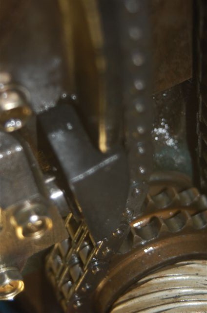
 If you loosen all 6mm bolts holding two guides and tensioner then press here (see below), the slack in the tensioner will disappear. FYI I used a socket extension as a lever to pry the top of the right (relative to driver) guide as opposed to using my finger as in the diagram. I then tightened the tensioner, the curved guide then finally the straight guide,
 -
Put the grommet in boiling water to soften it.
-
btw your Z looks like the better of the two

-
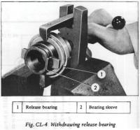
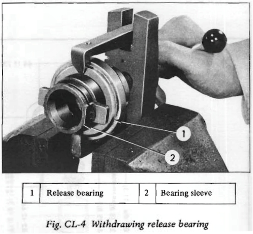
I cleaned up the collar with scotchbrite pad, put it in the freezer, placed on a block of wood, then tapped the bearing in place using a hammer and big socket. The socket should not press against the bearing shell. It should only press against the inner ring of the bearing as in the drawing above. You may be able to do this with a C-clamp too. Some antiseize on the collar may help. I just did it dry.
-
You should change your handle to Warhol or Picasso! That stuff is brilliant!!!! I bet you could take it to London TATE or NYC MOM then put in a gallery and get $5k to $50k for each piece! GO GO GO Make $$$$ from your genius! You are an artist! Get out there and make more and sell! http://online.wsj.com/article/SB10001424052748703551304576261042931202326.html
-
I like the Panasonic SLR-like for combining convenience, distance, glass, and noise. I bought my daughter a Canon T2 plus a telephoto and she takes wonderful shots with it. Of course these days it is the digital post editing that can make a photo "pop". As above, get what you like. Further more, it is great to have a small compact with good glass to have in your pocket when you don't want to drag the camera bag. These two sites should help a lot: http://www.dpreview.com/ http://www.steves-digicams.com/
-
Or if you are in a rush. Slit the grommet with a razor, install on harness, then use an appropriate glue to repair the grommet. 3M most likely have a product.... maybe even the black weatherstripping adhesive will do the job nicely.
-
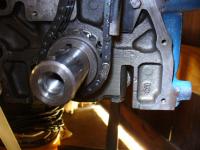
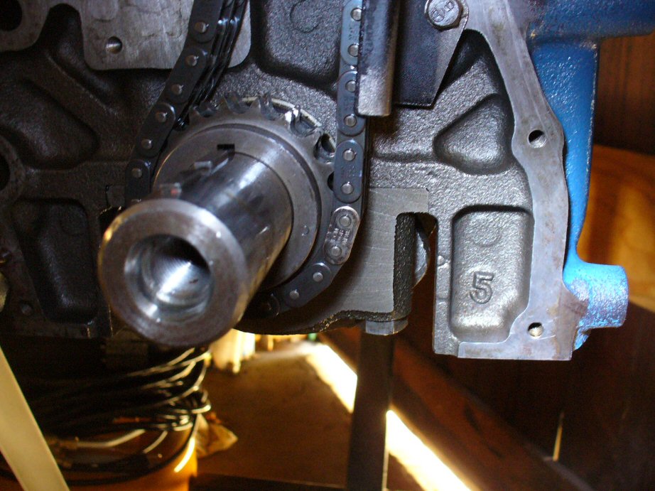
FYI the photo thumbnails (not drawings) at the bottom of post #2 are not correct. I was unable to remove from the post however I did not enlarge them. In this photo, you can see the timing chain is loose and the tensioner is already extended: WRONG WRONG WRONG: More than 0mm of extension (one should not see the silver shaft of the tensioner) WRONG WRONG WRONG: More than 0mm of extension (one should not see the silver shaft of the tensioner)
-
Thanks!
-
72 fsm
-
Assembling new clutch kit. I forget how the old bearing was oriented. The new one is a Koyo RCT4075-1S that looks like this: The left picture above is flatter side with writing and the face metal wraps around to make the bearing side The right picture above is the rounder side and its face terminates ~ 2mm from the edge (you can see the gap). Which side faces towards the clutch (front of engine)? (I am stuck as it does not make sense to put ID where it will be chewed up, but the side with the less metal will be weaker...I would guess the left picture's side with the writing goes towards the clutch).
-
none of us can cast a stone at you.
-
I have read advice to have the depth so that it does not run where the past lip touched. Here is an online pic for reference:
Here is front, rear is the same. Just remember "Flat out" or "Show no lip"and you got it "loaded and locked".
Maybe a PO or shop put it in (along with other metal stuff) as an abrasive when cleaning the inside of the tank years ago. It could have hung up when they removed the abrasive years ago thus its reappearance now. Or maybe the PO's 5year old son/neighbour's son did it. (I stogged a potato in an exhaust pipe at 5.)
PARTS: CONFIGURATION: CAM TIMING ALIGNMENT: REMOVING SLACK:

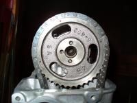

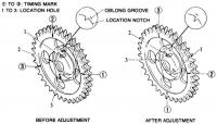

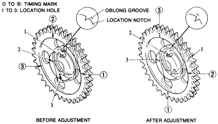
 For the archives: When following the FSM instructions and installing a new timing chain, this works: 0. Configuration: Head is on block with two middle cam tower head bolts at 14ft-lbs; head assembled; Cam sprocket is torqued to 100ft-lbs, Crank sprocket and Woodruff key is in place. Cam is at #1 and crank is at TDC. 71 L24 block with N47 maxima head. 1. Do not install chain guides or tensioner. 2. Drop chain through hole in front of head. 3. Wrap chain around crank sprocket with bright link next to dimple. 4. Firmly pull the chain up and wrap around cam sprocket with bright link next to #1 dimple. FYI the timing chain guides and tensioner prevent the chain from reaching over the sprockets (if you start from the bottom or top). This tip should save you a few minutes of noodling around. FYI#2 the photos in the Haynes manual show the timing chain tensioner with ~ 1cm of outward extension. This is incorrect.It should have 0 extension (see below). To take out the slack, adjust the top of the right side guide (above the tensioner) (see last photo below[not l24/26/28 block]). Moving this guide will pull the tensioner in. As well, ensure the lower end of the same guide is "in the shadow of the tensioner" rather than driven out into the rotating chain.
I have read where some drill a hole in the newer slave cylinder where they can hook the spring thus maintaining the function. Read post #7 here: Early Clutch Slave Drilling Spring Hole
Everything seems to work fine. I rotated it after reassembly with a screw driver.
Update: Finally getting ready to install the transmission and I popped it open to recheck the seal assuming I installed it incorrectly. It actually has a pressing surface on the back side for this purpose. The convoluted lip is facing in. Check twice, leak "nonce"
Thanks for the great photo. Mine looks like it may have been glued to both surfaces with kryptonite. Even after a night's soak in varsol it would not budge. I just used aviation form-a-gasket and reassembled. It should be a good test of the stuff.
M10X 1.5mm Just chased them. One was corroded and the head broke. I tried welding nuts to it but no luck. Took it to a shop and they had the same failures so I did not feel bad. The "old guy" attacked it differently and heated the bell housing... worked like a charm. I think the high current return to the starter through these bolts may accelerate the steel/aluminum/water electrolysis
Thanks guys! I'll pick one up. For the record: The cam is Delta 270/280 Valve Lift: 0.450" Intake and Exhaust Measured. Exhaust Cam Lift: 0.315" Measured Geometry Multiplier:1.43 Springs:Schneider 68022 110lbs @ 1.6" Retainer: Schneider 73004 Lash: 0.162" I had a peek through the springs and it looks like I have ~ 2-3mm between the top of the stock valve seal and bottom of the retainer at full lift.
When I disassembled the oil pump, the gasket was essentially none-existent, a paper-like surface was stuck to both parts more-or-less like glue rather than gasket. It can not be removed by finger nail. What should I do for reassembly? I am thinking that I leave the paper surface and use Aviation Form A Gasket? I can cut a new paper gasket with an xacto but I wonder if it is worth stripping the old stuff as it is bonded so well? I will have to use a chemical gasket remover to kick start it.
For the archives: When following the FSM instructions and installing a new timing chain, this works: 0. Configuration: Head is on block with two middle cam tower head bolts at 14ft-lbs; head assembled; Cam sprocket is torqued to 100ft-lbs, Crank sprocket and Woodruff key is in place. Cam is at #1 and crank is at TDC. 71 L24 block with N47 maxima head. 1. Do not install chain guides or tensioner. 2. Drop chain through hole in front of head. 3. Wrap chain around crank sprocket with bright link next to dimple. 4. Firmly pull the chain up and wrap around cam sprocket with bright link next to #1 dimple. FYI the timing chain guides and tensioner prevent the chain from reaching over the sprockets (if you start from the bottom or top). This tip should save you a few minutes of noodling around. FYI#2 the photos in the Haynes manual show the timing chain tensioner with ~ 1cm of outward extension. This is incorrect.It should have 0 extension (see below). To take out the slack, adjust the top of the right side guide (above the tensioner) (see last photo below[not l24/26/28 block]). Moving this guide will pull the tensioner in. As well, ensure the lower end of the same guide is "in the shadow of the tensioner" rather than driven out into the rotating chain.
I have read where some drill a hole in the newer slave cylinder where they can hook the spring thus maintaining the function. Read post #7 here: Early Clutch Slave Drilling Spring Hole
Everything seems to work fine. I rotated it after reassembly with a screw driver.
Update: Finally getting ready to install the transmission and I popped it open to recheck the seal assuming I installed it incorrectly. It actually has a pressing surface on the back side for this purpose. The convoluted lip is facing in. Check twice, leak "nonce"
Thanks for the great photo. Mine looks like it may have been glued to both surfaces with kryptonite. Even after a night's soak in varsol it would not budge. I just used aviation form-a-gasket and reassembled. It should be a good test of the stuff.
M10X 1.5mm Just chased them. One was corroded and the head broke. I tried welding nuts to it but no luck. Took it to a shop and they had the same failures so I did not feel bad. The "old guy" attacked it differently and heated the bell housing... worked like a charm. I think the high current return to the starter through these bolts may accelerate the steel/aluminum/water electrolysis
Thanks guys! I'll pick one up. For the record: The cam is Delta 270/280 Valve Lift: 0.450" Intake and Exhaust Measured. Exhaust Cam Lift: 0.315" Measured Geometry Multiplier:1.43 Springs:Schneider 68022 110lbs @ 1.6" Retainer: Schneider 73004 Lash: 0.162" I had a peek through the springs and it looks like I have ~ 2-3mm between the top of the stock valve seal and bottom of the retainer at full lift.
When I disassembled the oil pump, the gasket was essentially none-existent, a paper-like surface was stuck to both parts more-or-less like glue rather than gasket. It can not be removed by finger nail. What should I do for reassembly? I am thinking that I leave the paper surface and use Aviation Form A Gasket? I can cut a new paper gasket with an xacto but I wonder if it is worth stripping the old stuff as it is bonded so well? I will have to use a chemical gasket remover to kick start it.


Important Information
By using this site, you agree to our Privacy Policy and Guidelines. We have placed cookies on your device to help make this website better. You can adjust your cookie settings, otherwise we'll assume you're okay to continue.