Everything posted by SteveJ
-
-
The diagram you posted from the FSM shows a points style voltage regulator aka the bimetal strip. The strip opens the points in a manner similar to the voltage regulator in the charging circuit. Where is the error? The voltage regulator is on the right side of the fuel gauge. And it's on the left side of the oil pressure gauge where it is also wired to the temp gauge. By the way, it looks like the Triumph guys have been replacing the bimetal strip regulator with a solid state regulator. Voltage stabilizer for temp and fuel, anyone going solid...I'm trying to calibrate my fuel and temp gauges, but find myself fighting the bi metal voltage stabilizer.. I plan on going for a 10v solid state unit. Has anybody else done this?This link shows the internals. https://forum.triumphdolomite.co.uk/viewtopic.php?f=5&t=4550


-
-
I have not tried this...yet, but I see a garage project coming. Ratsun ForumsBad gauge cluster voltage regulator? Easy $2 fix.Problem You're temp/fuel gauges don't work and you've already checked the output from your fuel/temp sensors to make sure they are not the culprit. You checked continuity of the wires from the sensor
-
Here are a couple of videos on the fuel gauge: Basically, you're not testing the gauge properly. To bench test the gauge, you need to connect 12VDC+ to the green wire, ground the black wire, and run the yellow wire through a resistor that is grounded on the other side. You should have 12VDC+ to ground at the green wire coming into the gauge when the key is in ON. There is a voltage regulator in the gauge as discussed in the videos above, and the yellow wire comes off the regulator and goes to the fuel level sender. You should measure voltage to ground at the yellow wire at the gas tank with the key in ON. When the key is first turned to the ON position, you should see about 12VDC to ground at the yellow wire. As the voltage regulator warms up, you will see the voltage fluctuating. You can also ground the yellow wire at the gas tank for a short period of time and have someone see if the needle moves on the gauge.
-
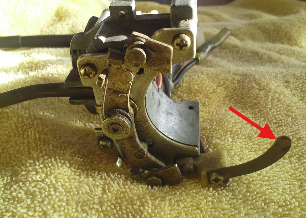
Did you get instructions with the hub about connecting the horn? I haven't touched a Momo hub in years, so I cannot recall how it was set up on the horn button. Are you sure the tab on the turn switch is making contact with the horn ring on the back of the steering wheel? Is the steering wheel grounded such that when you press the horn button, it completes the path to ground on the horn ring?
-
When was the last time you heard your horns work? The way the circuit works is that the GR wire comes from the fuse to the horn relay. The GB wire goes to the steering column to the copper tab on the turn signal switch. When you press the horn button, the GB wire is grounded. That should complete the circuit for the coil on the horn relay. At that point the GR wire and G wire are connected, completing the circuit out to the horns. To test the relay, take the GB wire off the relay and use a clip lead to ground the S terminal on the relay. (See below.) Ideally, you should hear the horns. Hopefully you at least hear the relay click. With 12VDC+ on the B terminal and the S terminal grounded, you should have 12VDC+ to ground on the H terminal. When I was waking up my 73 from 11 years of slumber, I tested my horns. They didn't work. I tracked the problem down to corrosion on the horns where the green wire connects to them.

-
-
I was recently wondering about him, too. I didn't realize he's been away from here for 3 years.
-
Well, I would expect to see 13.5VDC up to 15VDC. The voltage fluctuations shouldn't be too much, less than half a volt. The fluctuations could be an issue with the charging system, battery, or ammeter. Smooth voltage would have me look at the ammeter more.
-
Do you still have the old style points regulator? If it's slow to open and close the contacts, I could understand that as a result. If the lighter is working, you could get a USB adapter like this to monitor the voltage while driving: https://www.amazon.com/Charger-Adapter-Voltage-Cigarette-Charging/dp/B0C9DLDN19
-
On the relay pins 4/47 and 76 (86 and 86a) are the positive for the relay coil circled below. At that point, the WR wire coming to pin 73 (88y) should be connected to pins 48 and 74 (88C & 88d). So here's what I suggest. Check for continuity between terminals 86 and 86a. With the relay plugged in, check for voltage to ground at 86 with the key in start. (You can save wear and tear on the starter by unplugging the black/yellow wire at the solenoid before doing the test.) Check voltage to ground at the ECU harness on pin 4 with the key in start.

-
Bot you say?
-
Wait until you find out about power tools...
-
M16.4 - https://www.rockauto.com/en/moreinfo.php?pk=3270447&cc=1209169&pt=10231&jsn=605 That is approximately 5/8, but I'm not sure
-
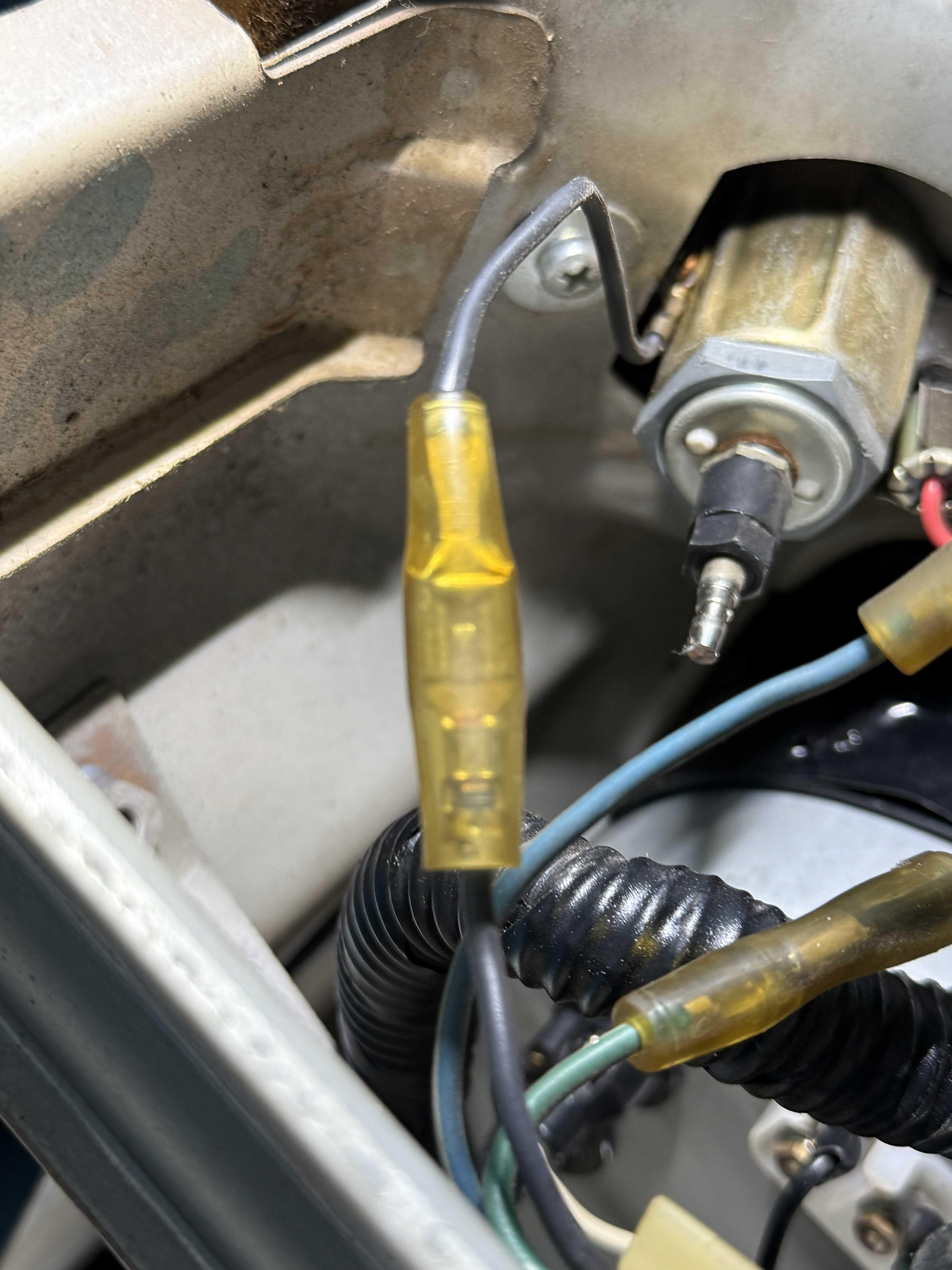
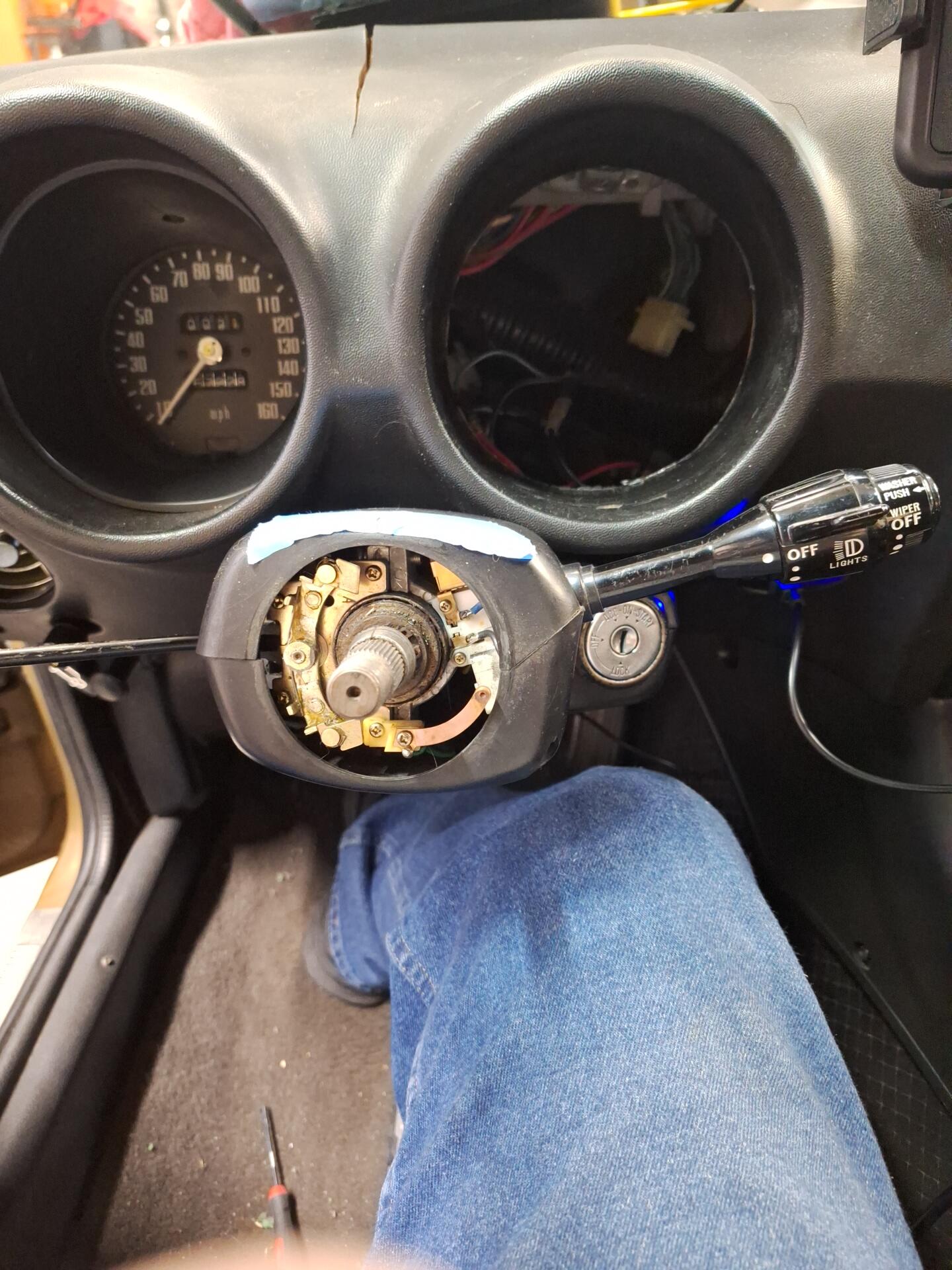
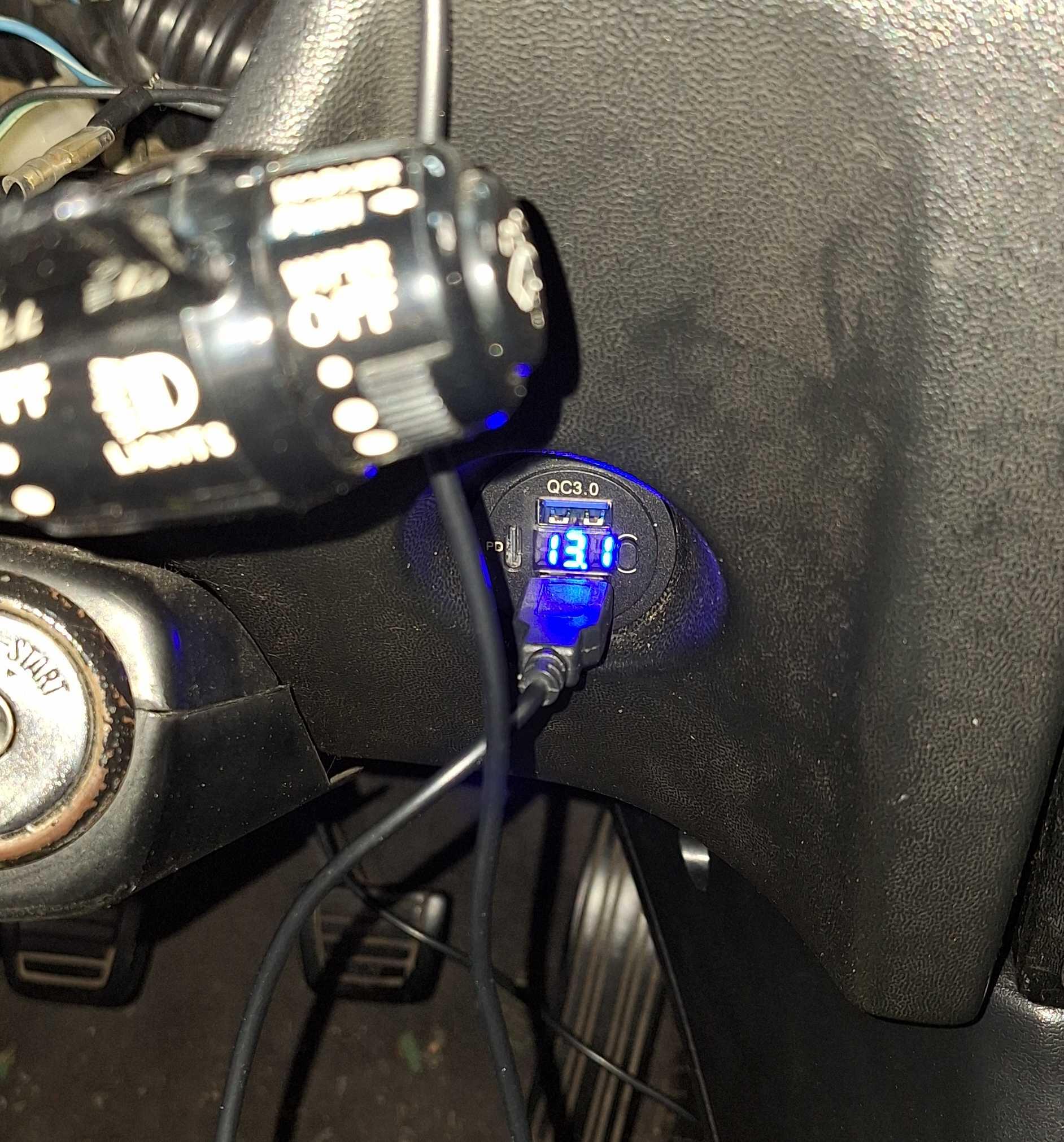
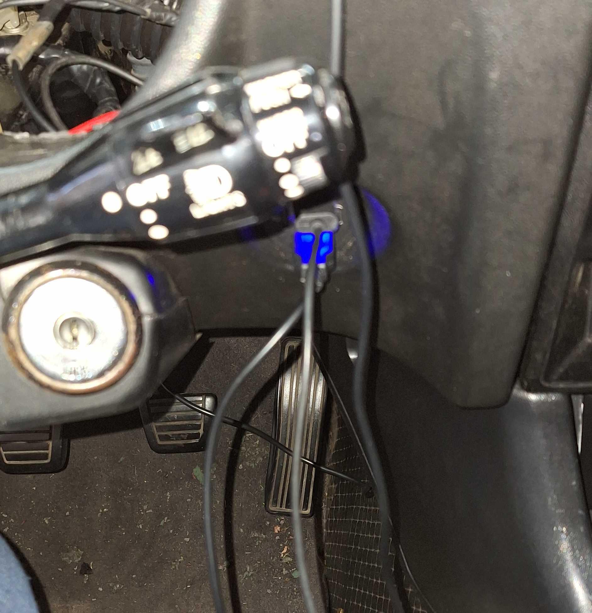
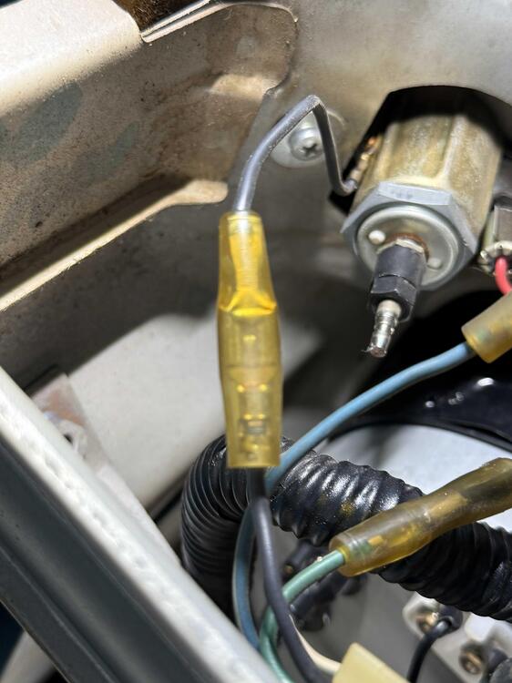
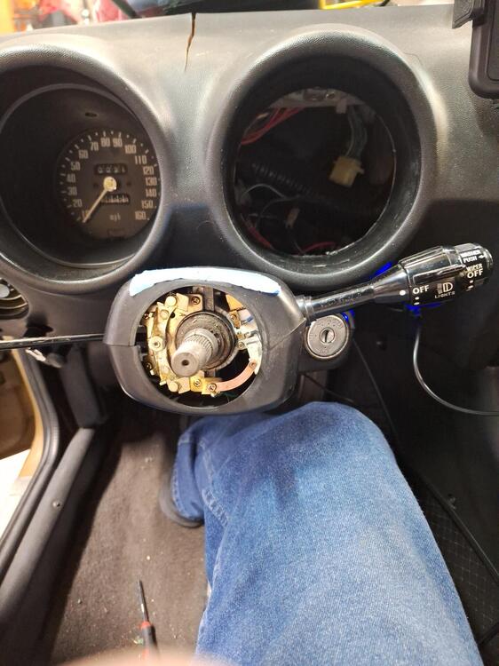
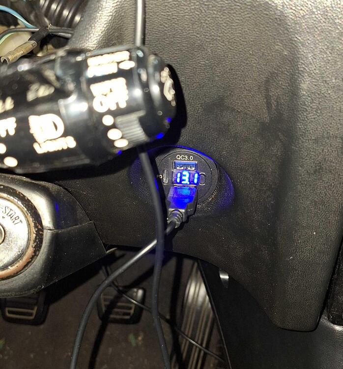
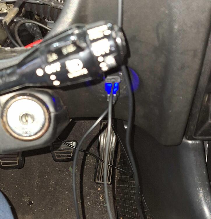
I finally did something with my 260Z today. I replaced the cigarette lighter with a USB port adapter that has 2 Type A ports and one Type C port. If you're interested in doing this, you may want to buy one with an on/off button since the circuit for the lighter is hot all of the time. To match up with the car's wiring, you'll need to attach a male bullet connector to the positive wire and a female spade (6.3mm) to the negative. Installation: Remove the fuse for the lighter. (For 280Z & 260Z) Remove the fuse for the horn so you don't honk the horn while trying to get the horn button off. Remove the steering wheel. Remove the tachometer. This gives you access to the back of the lighter. Remove the retaining nut on the back of the lighter. Disconnect the negative and positive wires. Tip: Slide a pick under the insulation for the negative to break the adhesion. Pull out the lighter and remove the surround. Use a step bit to enlarge the opening to 28mm or 1 1/8 inches. Video below. Once the hole is the correct size, insert the USB adapter and install the retaining nut on the back side. Two tips: 1. Plug a cable in the USB adapter to hold it in place while tightening the retaining nut. 2. I used a 90 degree pick to turn the retaining nut when the dash frame made it where I could no longer turn the retaining nut with my fingers. Connect the positive and negative wires. Replace the tach, steering wheel, and horn button. Replace the fuses. Enlarging the opening: While the adapter has a voltmeter, it is recessed in the lighter opening and blocked by the headlight switch. You could lean over and see it, though, as long as you don't have a cable plugged into the top port.
-
Cast impeller water pump: https://www.amazon.com/Aisin-WPN-013-Engine-Water-Pump/dp/B008EEZ2XY
-
When I searched ebay for the iBooster, I actually looked more at the Hondas because I don't think they have the booster mounted at an angle like the Tesla. I'm still not sure about what reservoir would be best to use in this application.
-
An ammeter can fail, but that would also cause the car not to run. Bad wires at the ammeter would also cause the car not to run.
-
The ammeter doesn't really have good resolution, especially the ones that range from -60 to +60. Also I have no idea whether or not the one on @70z4fun's car has been zeroed out properly. Also consider the first test in the FSM for the alternator is to check the voltage. Why not make it easy and use a digital meter in the car? Also, one other thing I just remembered. Sometimes people add additional electrical loads to a Z and connect on the battery side of the ammeter. That could give a false indication of a failing alternator.
-
You could buy a cigarette lighter USB adapter like this: https://www.amazon.com/dp/B0C9DLDN19 It has a built in voltmeter. If you see it dropping below 13VDC while driving, you have a good clue that the alternator isn't putting out current or your battery is going bad.
-
Are you talking about the white and white/red wires at the fuse box? They branch off the wires going to the ammeter. I suggest not speculating too much. You will confuse yourself. Don't throw parts at problems. Diagnose.
-
FYI, I diagnosed a bad EFI relay on a 77 and told the owner to get the relay that @EuroDat said to buy. He got that relay, slapped it in, and the car ran just fine.
-
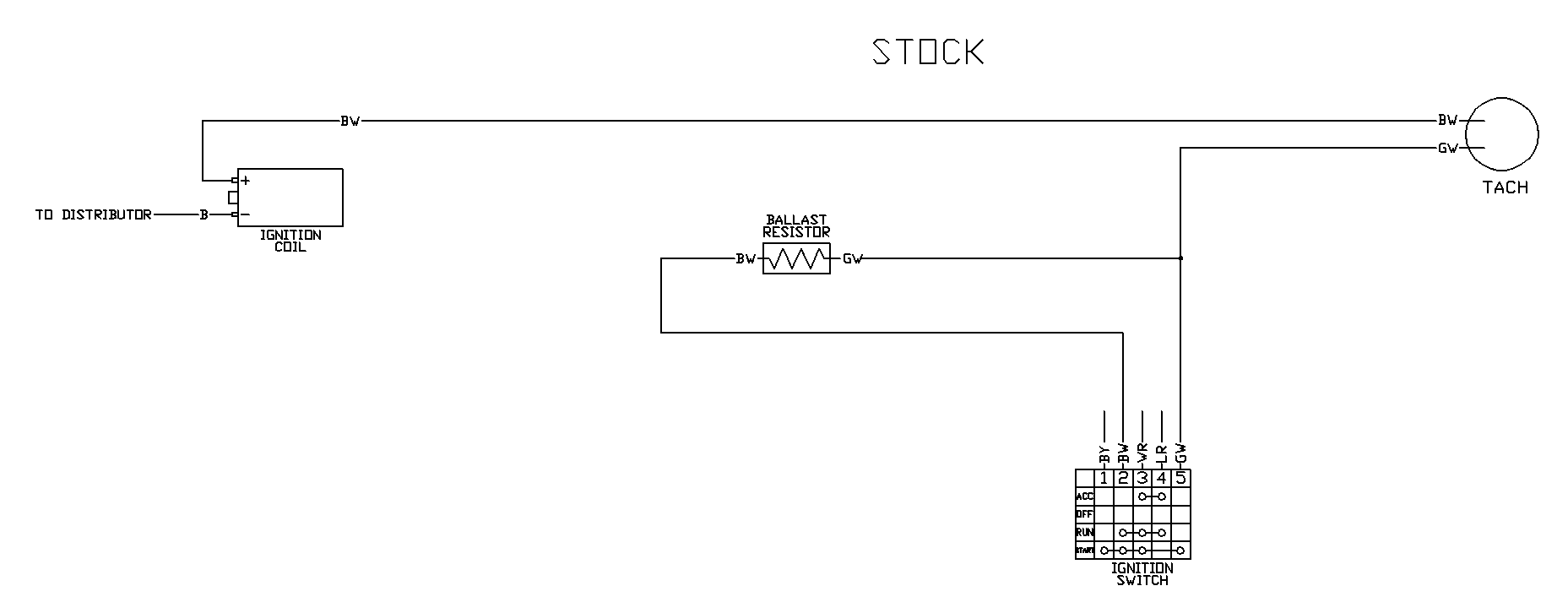
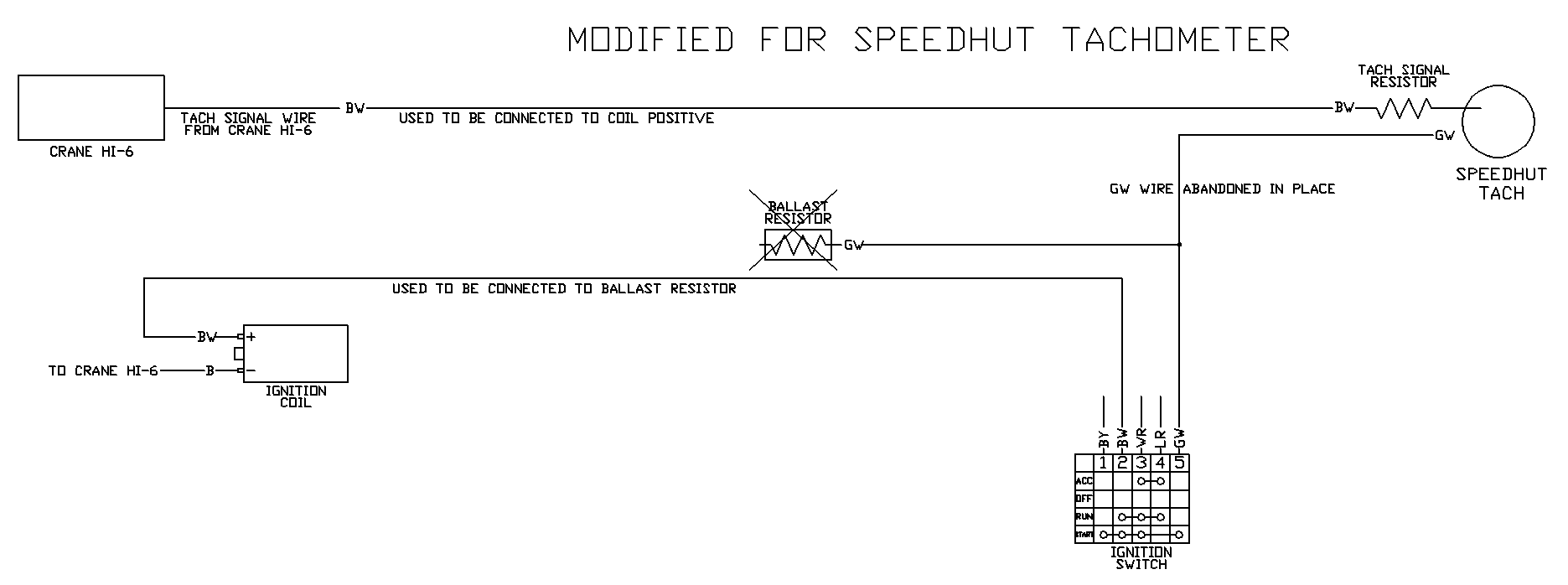
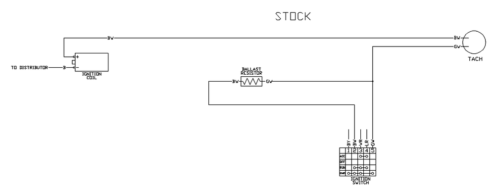
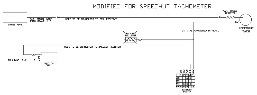
To combine what we talked about on the phone with the guidance from @cgsheen1, here is the stock wiring. This is essentially what the modified wiring would be.
-
While the wiring diagram shows a fusible link at the alternator, I personally have never seen it in the wild. The output from the alternator goes to the battery through the ammeter. If you do not have continuity from the alternator output to the battery, that usually indicates the ammeter failed or the fusible link at the starter failed. In either case, the car would not start/run (unless it was hacked up by a previous owner).