inline6
 Subscriber
-
Joined
-
Last visited
Everything posted by inline6
-
 (edit): Whoops, just noticed that what you are trying to do isn't match factory - so disregard. I was quite interested in this topic a while back. I think the best replica I have seen is what was used here (starting at about 6:25):
 -
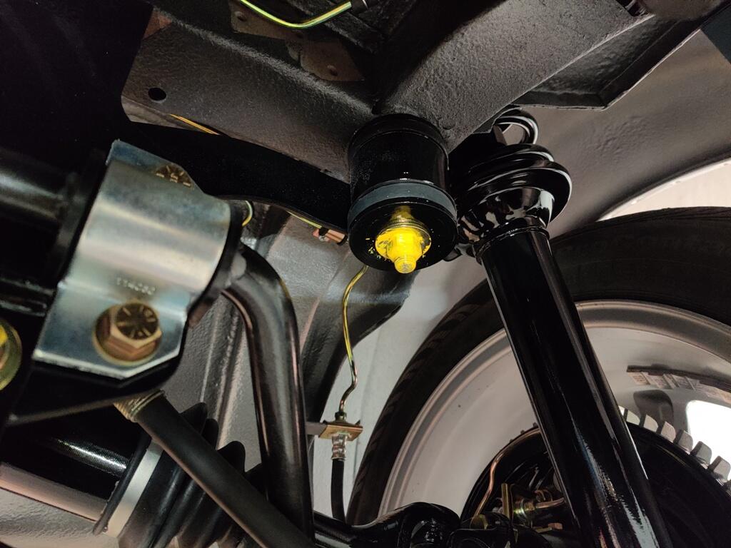
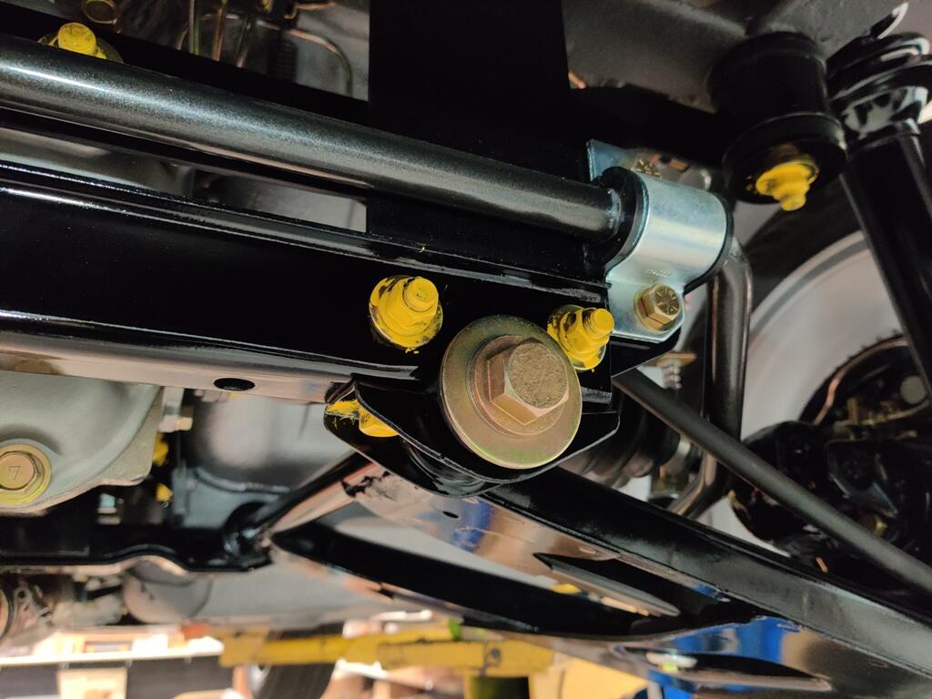
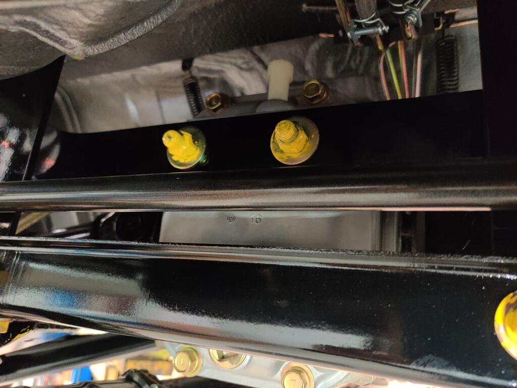
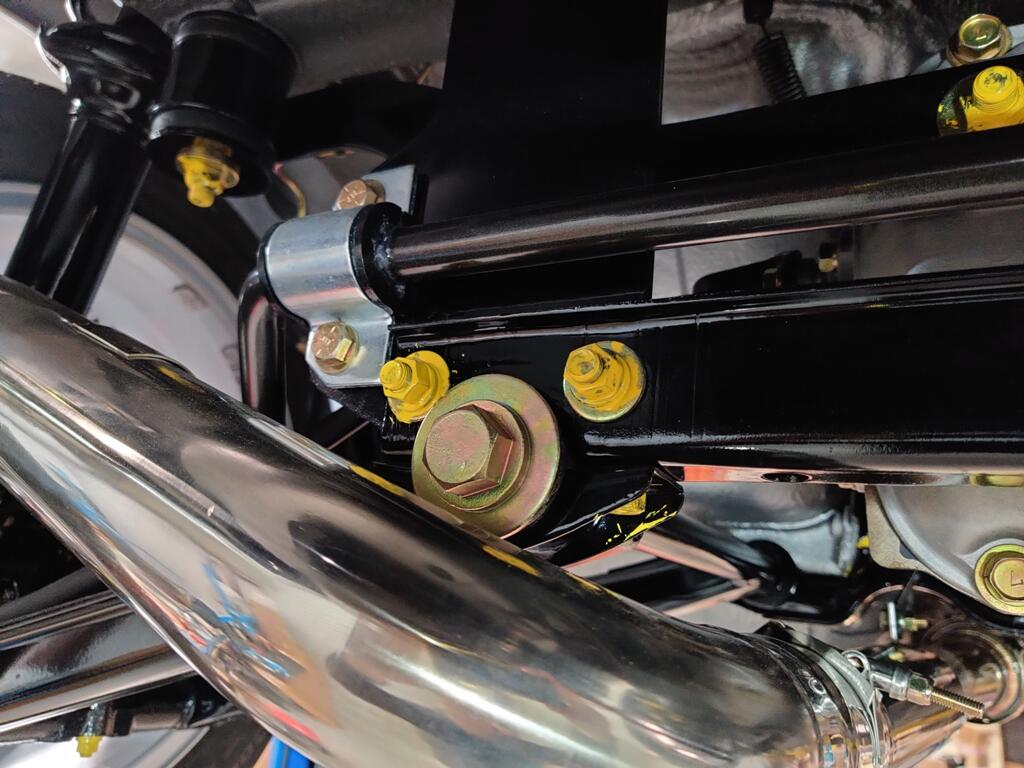
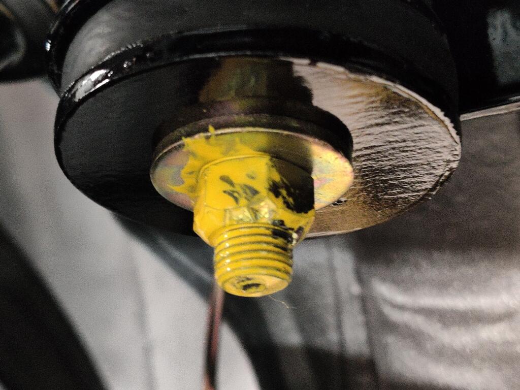
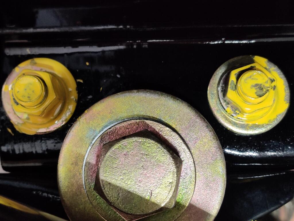
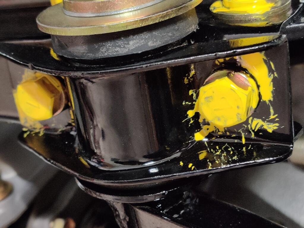
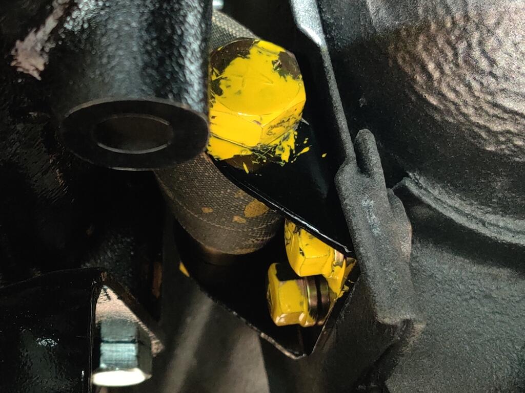
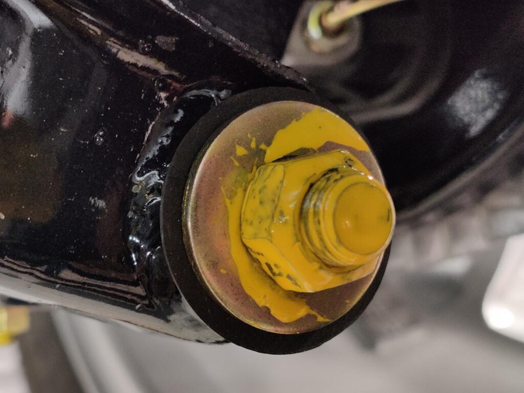
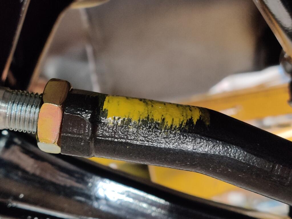
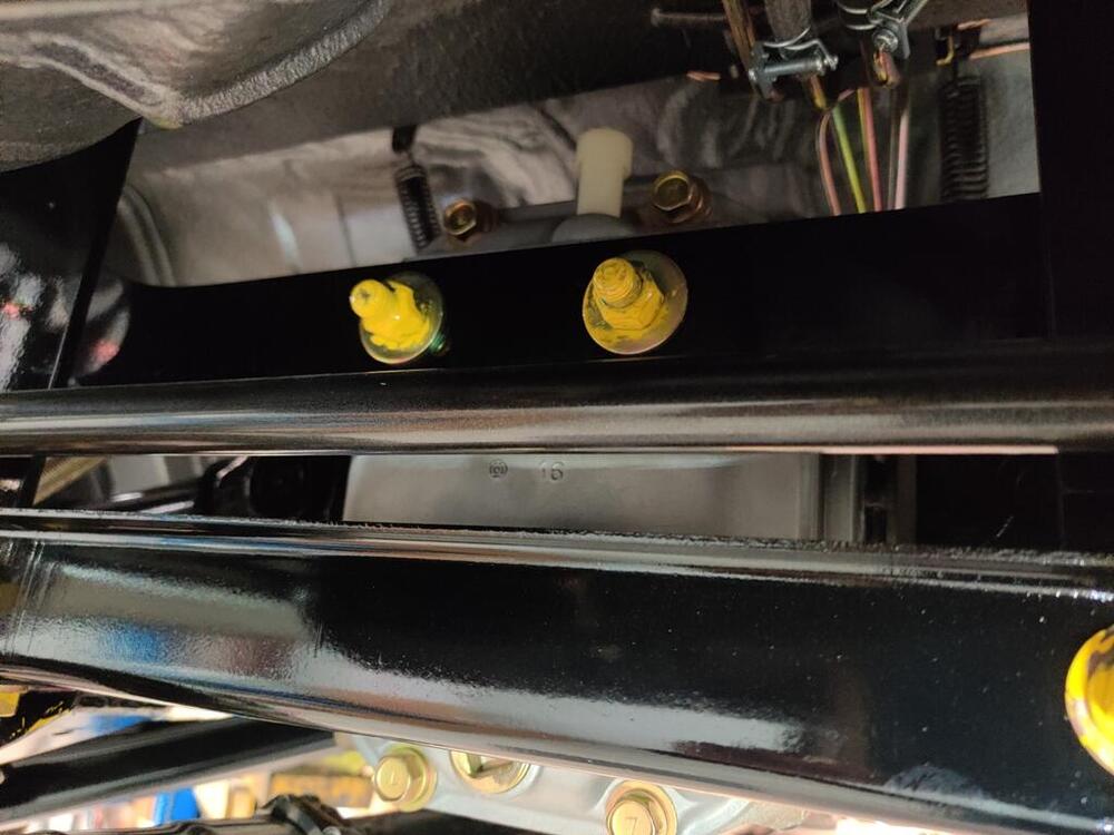
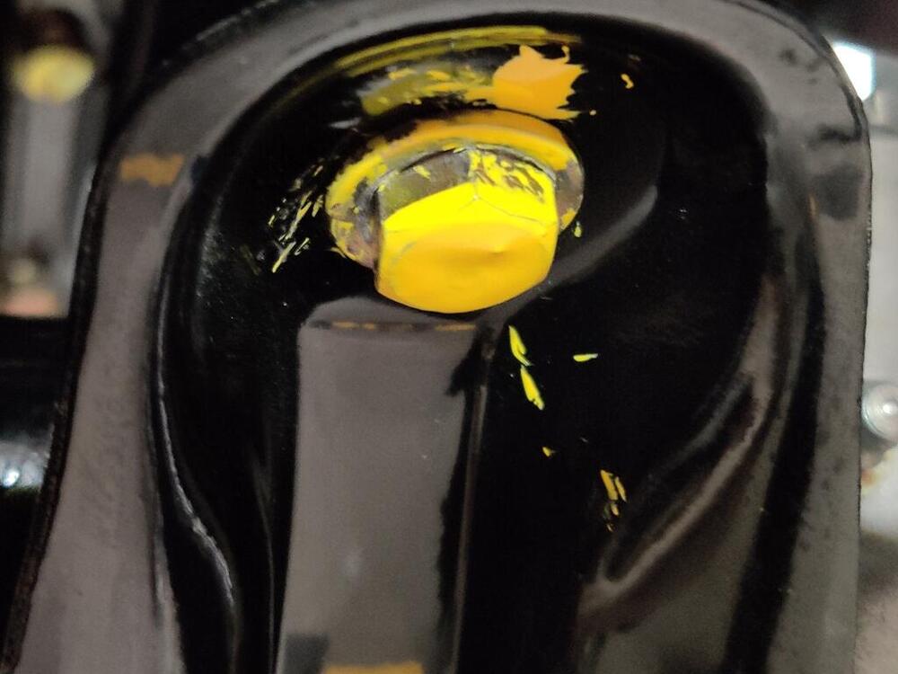
Right, my understanding is that the yellow paint marks were applied at the factory to indicated the fastener had been torqued. If you have a look at the paint markings on the 240z that sold on BringaTrailer for $310,000 US a few years ago, starting at about picture number 168, you will see that the paint was applied quite messily: https://bringatrailer.com/listing/1971-datsun-240z-124/ And, for what it is worth, I personally torqued all of these fasteners to spec!

-
Let the chrome people know. You don't want to pay for their time to try to fix that rust area.
-
A cold start video:
-
Anyone have any of the "short" luggage straps on hand? I need measurements of the lengths of both parts of one. Unfortunately, during restoration of mine, I didn't think it through, and I sent long ones as patterns to replicate. So, I have restored long ones now.
-
I think I'd recommend seeing if you can find some better escutcheons (inner door handle trim), Charles. I don't recall seeing many as rusty as those. So, I think you will have a good chance at finding some nicer ones to either use as is after a bit of polishing, or as better restoration candidates.
-
This is great - thanks for doing this!
-
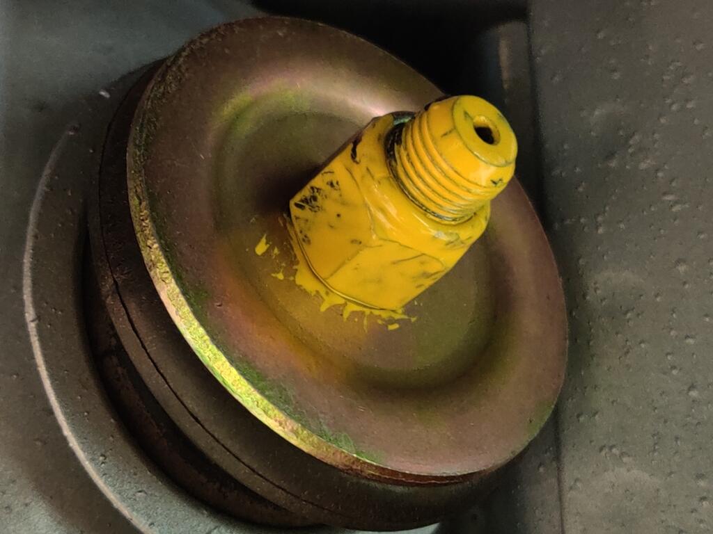
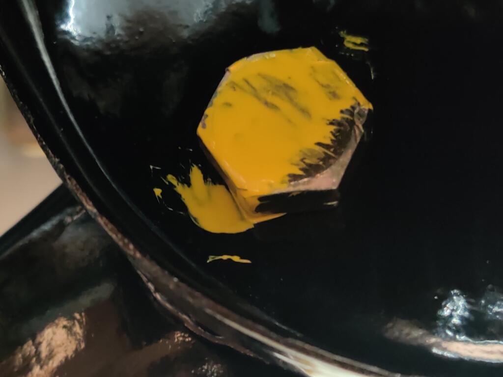
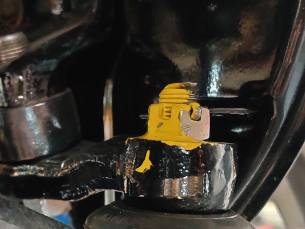
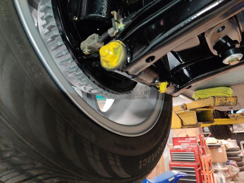
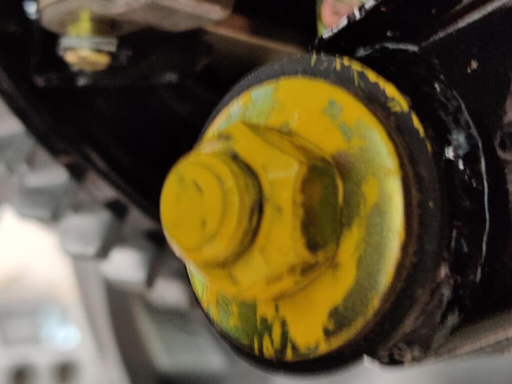
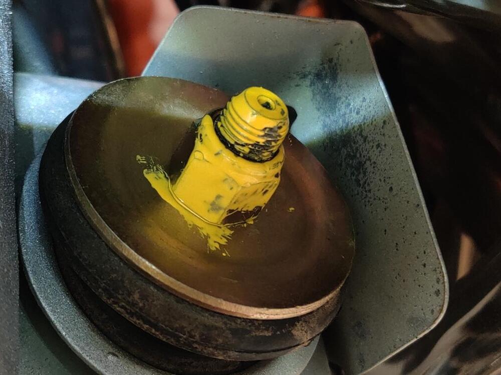
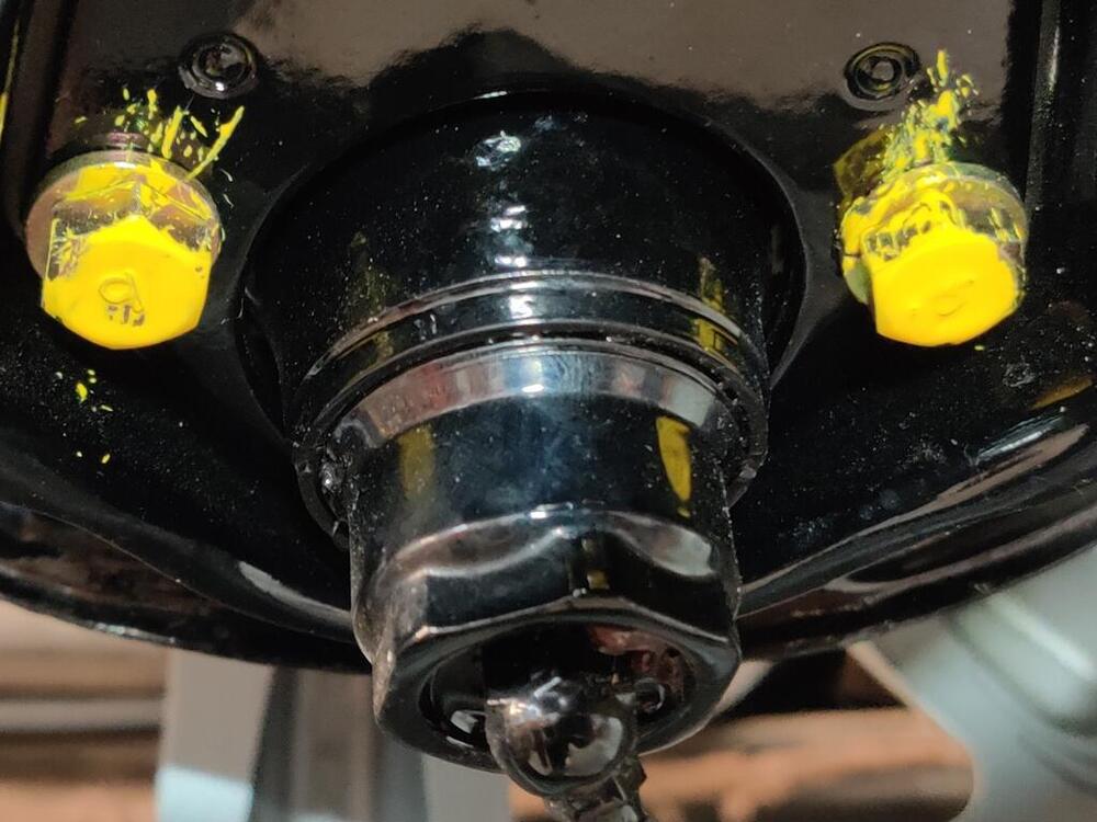
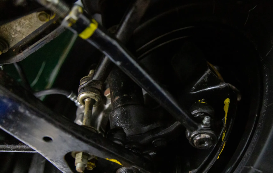
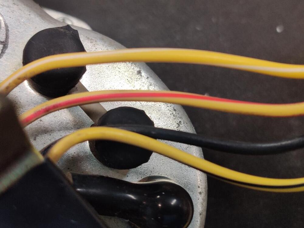
I had some fun putting yellow paint on the suspension bolts yesterday. I took some a bunch of closeups. The last picture above is of the left outer tie rod end. As taken out of the box, it had a yellow paint swipe across the top. I'm not sure what that means. The "green monster" on BAT has a yellow paint mark that goes around the rod.


-
I couldn't find anything that was like the original. I bought the Essex version of this as temporary solution. It is pile. https://www.rockauto.com/en/moreinfo.php?pk=6070062&cc=1209147&pt=1264&jsn=454 I tried to take the jute off of the back of one of the pieces that goes behind the seats as a test - I wanted to install all of the pieces of this carpet with the jute I got from England which looks kind of like the original jute. Unfortunately, the jute couldn't be pulled away from the carpet backing without damaging the carpet. The carpet backing is super thin, and the glue wouldn't let go without pulling tufts of carpet with it. The kit as received is nice. It fits well and I think it would be durable enough. But, it isn't like the original (neither is the loop version).
-
The one I used:
-
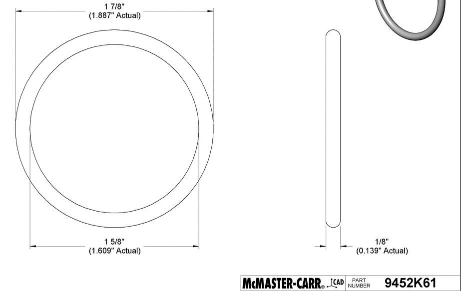
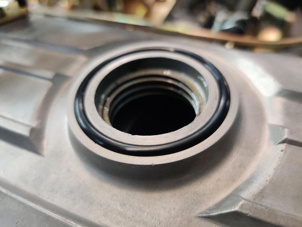
Interesting! My valve cover is the later "Nissan OHC" type but has the groove. VIN 35883 - 6/1971
-
I have 99 on hand - Oil-Resistant Buna-N O-Rings! I had to buy 100 to get the right thing. Give me an address and cover shipping - I'll send you one.
-
Anyone have a full set of these? I can't find any in my parts stash, and my brakes are squealing something fierce.

-
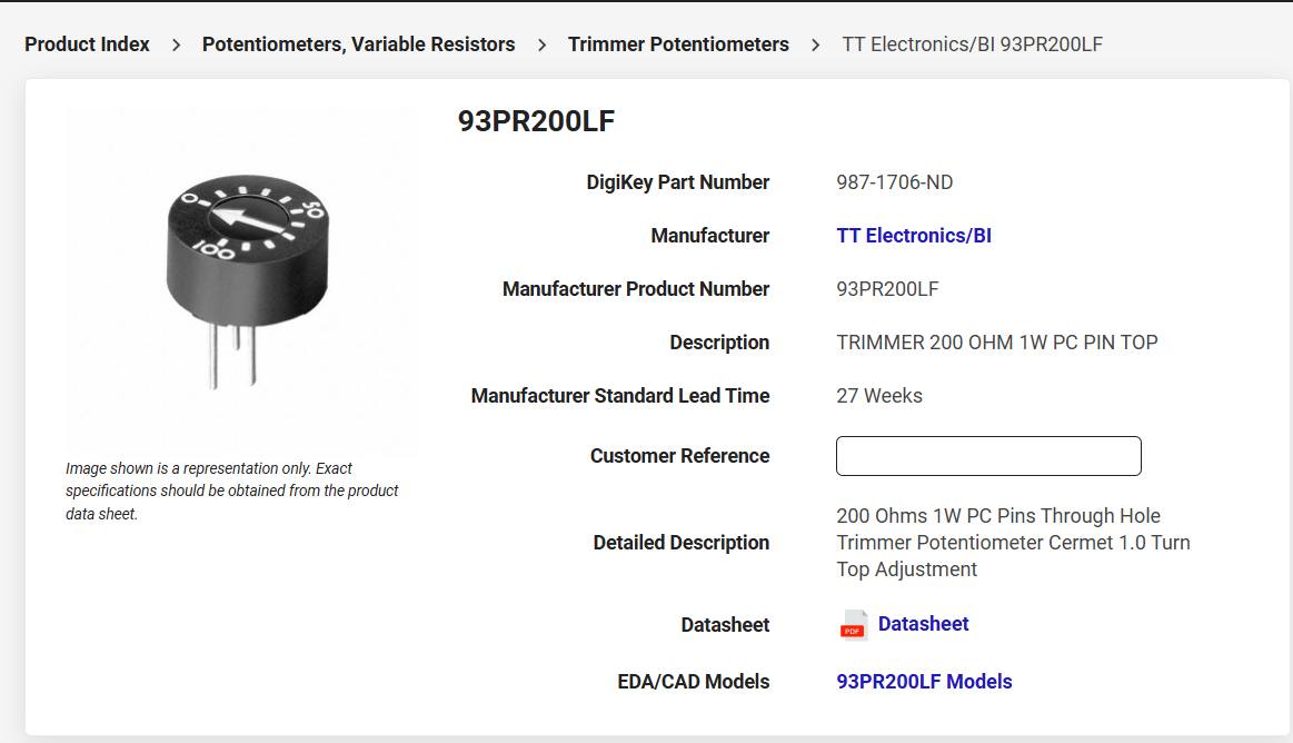
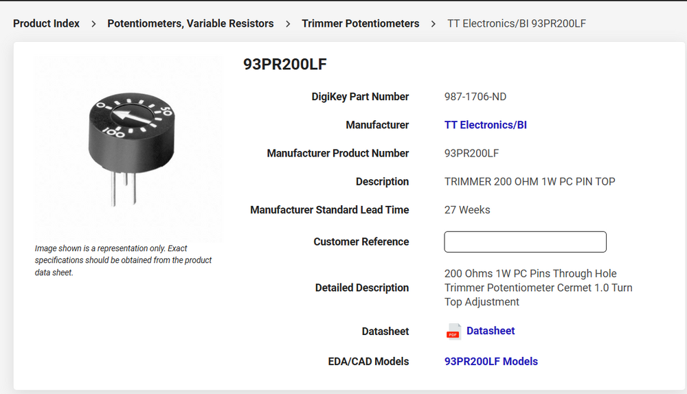
So this one - if anyone else wants to do this. https://www.digikey.com/en/products/detail/tt-electronics-bi/93PR200LF/5957450
-
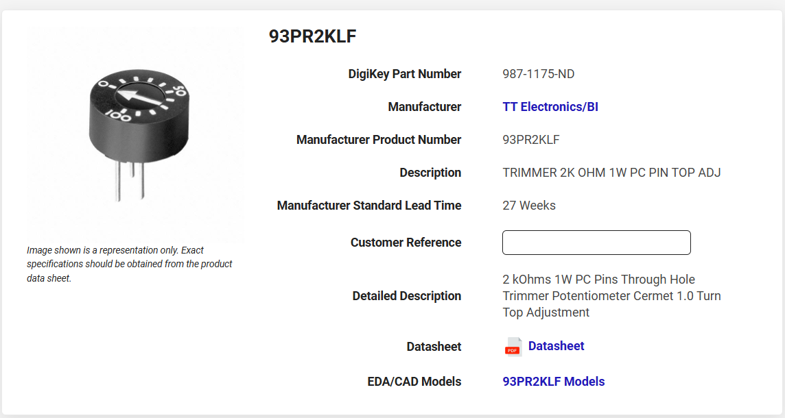
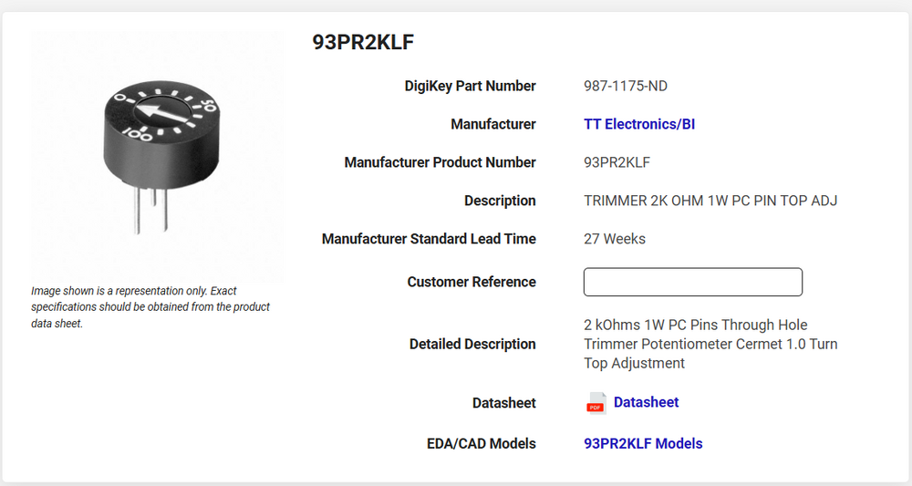
Y/B goes to the oil pressure. I opted for the easy way out today - instead of bench testing like I described previously, I looked up how to wire the "trimmer potentiometer" that @SteveJ put me onto. https://www.digikey.com/en/products/detail/tt-electronics-bi/93PR2KLF/2408753 I didn't know how to wire it up, but found something online that said to hook the middle pin to the wire of what I wanted to attenuate. I left the dash wiring alone. Instead, I removed the spade corresponding to the Y/W wire from the 4 spaded plastic connector. Then I took a new piece of insulated wire and put an identical spade on one end and put that into vacated spot in the 4 spade connector. I stripped a bit of the insulation from the other end of that wire and soldered it to the center pin of the trimmer. Then I soldered the original male spade attached to the Y/W wire which is bolted to the gauge to one of the other pins in the trimmer. I didn't snag pics, but I will. I found that when I used a small screw driver to adjust the trimmer to "0", the temp gauge worked as before. When I just barely moved the adjustment to just off of zero, the needle on the gauge dropped. The needle was super sensitive to any adjustment, but I got lucky on my 4th try to find something just off of "0". I drove around the neighborhood and watched as the needle came up to the line near the middle of the sweep of range and sat there. 🙂 I replaced all of the gauge bulbs with led bulbs while I had the center dash panel out again. So, now I just need to button up things.
-
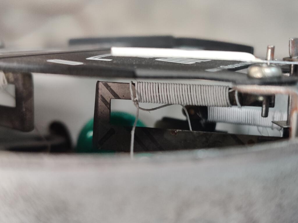
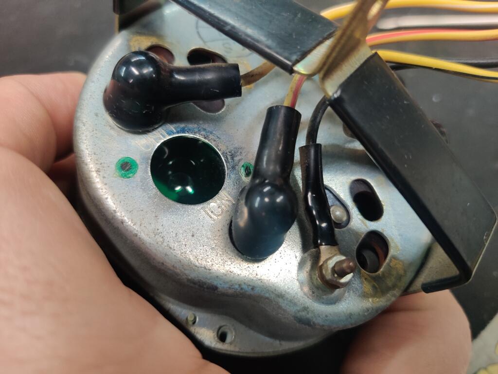
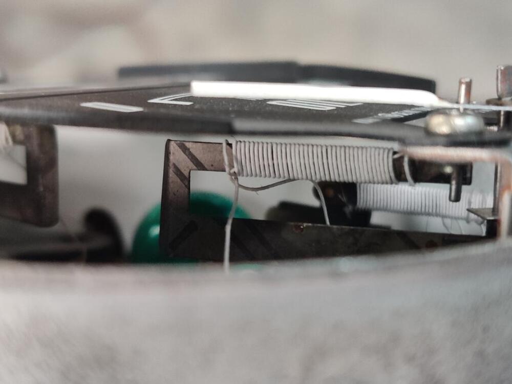
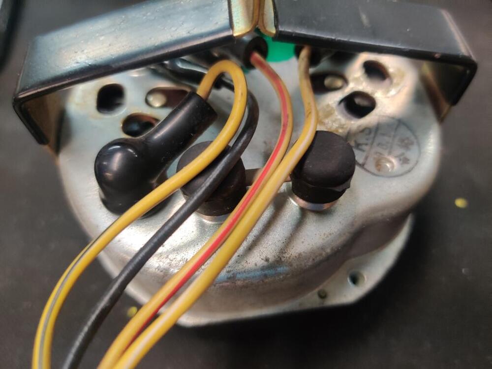
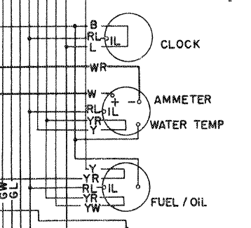
Dash harness wires: gauge wires: Inside gauge: Connections on gauge: Static needle positions: I didn't see the white strip before. I just glanced at the factory 1971 workshop manual and got the color codes: Funny how that has the ammeter and water temp in one gauge and the fuel and oil in the other! I was able to bench test just briefly yesterday. I pegged the gauge successfully. But, I couldn't juggle heating the temp sensor and getting a laser temp reading and seeing the needle position all at once. I am thinking about putting the sensor in a pot of boiling water to control the temp while connecting the body of the temp switch and ground of the gauge to a negative terminal of a battery... and the yellow/white wire to the positive terminal of a battery. I am thinking that will give me a fairly steady state for the heat, and I can also measure the resistance of the temp switch at the same time. Where the needle sits at that point will, in theory, be 212 degrees or thereabout. Then, I can add the "pot" that I bought for adjusting the resistance. I note that the gauge itself has some resistance as well. I will check that again and put what I find here.


-
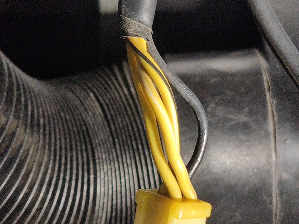
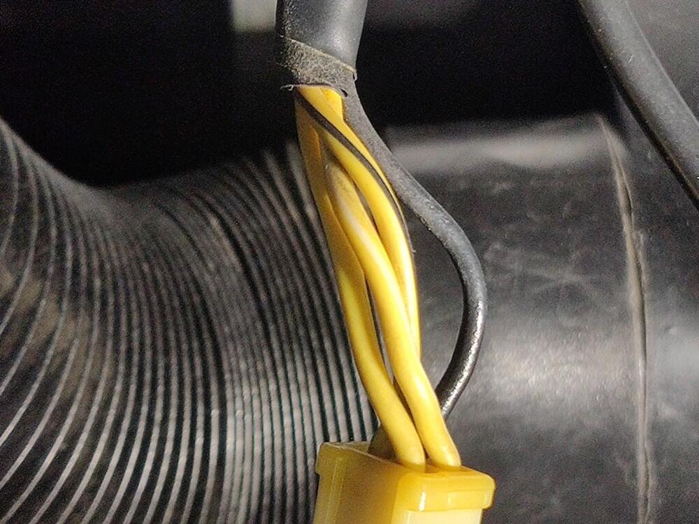
Wires for the temp portion of the gauge appear to be YR - yellow with red stripe (to power/voltage) Y - yellow (to temperature sender switch) B - black (to ground) If I hook up black and yellow (without the temperature sender), and yellow with red stripe to positive of a battery, I think I should see the gauge needle peg. If I hook up black and yellow (with the temperature sender in line), and yellow with red stripe to positive of a battery, I think I should see the gauge needle move, but movement will be dependent on the temperature of the sender. Because both the temp and oil pressure share the voltage regulation, will I need to hook up wires to it (the oil pressure gauge) also to perform my bench testing?
-
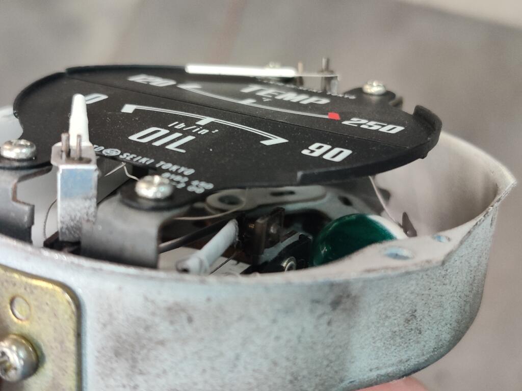
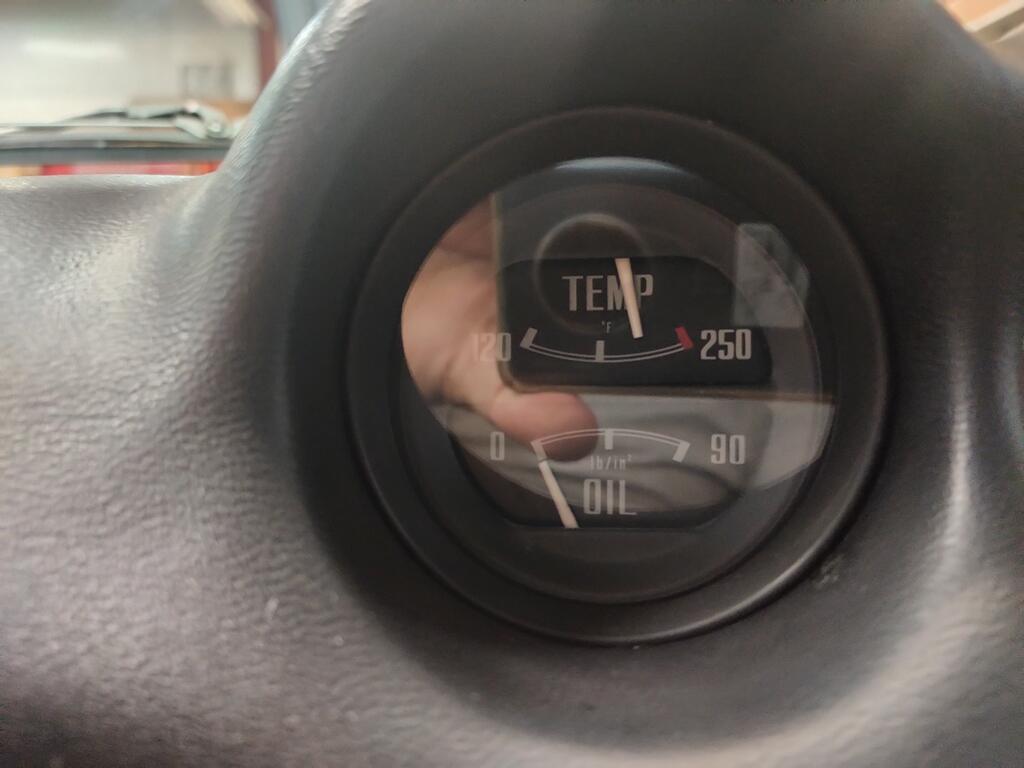
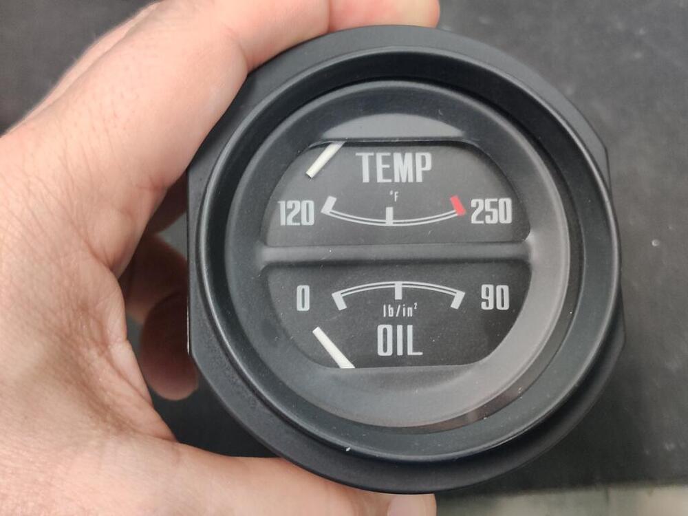
I do not know what my oil pressure is. I have not hooked up a mechanical gauge. Today, I noticed that when I set the key to the on position, both the temp gauge and the oil gauge needles move from their at rest positions. I never noticed that before. The temp gauge needles moves from pointing directly at the 2 in 120 to just a tad bit closer to the 0 in 120 (my laser gun indicated 70 degrees at the temp switch). And the oil pressure gauge needle moved from below 0 to pretty much right at 0. When I start the car, the oil pressure as indicated on the gauge goes up to almost max (90). When idling at a stop light, it is barely off of 0. I messed with the bi-metallic strip in the temp gauge today. I was able to get only slight improvement. Feels wrong to attempt to mess with it more. I think the bi-metallic strip would have to be drastically messed with to get the gauge to read correctly. I drove the car around for a few minutes to get the engine up to normal temp. I shut it off and took this pic after quickly returning the key to the on position. Temp needle is a bit lower than it what it was before messing with the bi-metallic strip - oil reads at 0 (it reads below zero with key off). My laser temp gun aimed at the sender switch showed about 146 degrees fahrenheit with the temp needle in this position in the gauge. I'd like to set up some bench testing. I'd like to be able to wire in a temp sender and apply heat to it, while at the same time measuring the resistance in the temp switch and the temperature of the heat switch... and viewing the position of the needle on the gauge. Would you be able to help me figure out how to wire that up @SteveJ? It would be nice if I could get the needle to show 120 when the temp switch is at 120, and to get the needle on the gauge to show 250 when the temp switch is at 250.

-
Is it possible that heating and cooling of the bi-metallic strip over the years... thousands of times could cause it to harden, can change it's original action? I also find myself wondering why the same gauge only read a little bit higher than the mark in the middle before the restoration, and now is so much higher. I can rule out the sender, I believe. I used the original one, and two additional ones with no real change to the high position of the needle now.
-
I got back to this today. I took my gauge out and the cover off. I found that my gauge does not have a screw. I should have taken some pictures, but I did not. After just now reading the above post you shared @Captain Obvious, I believe my gauge my be uncompensated? I only recall seeing the one U shaped bi-metallic strip with the white wire coiled around only one leg of it. It seems like to try to adjust it, I will need to bend part of the U?
-
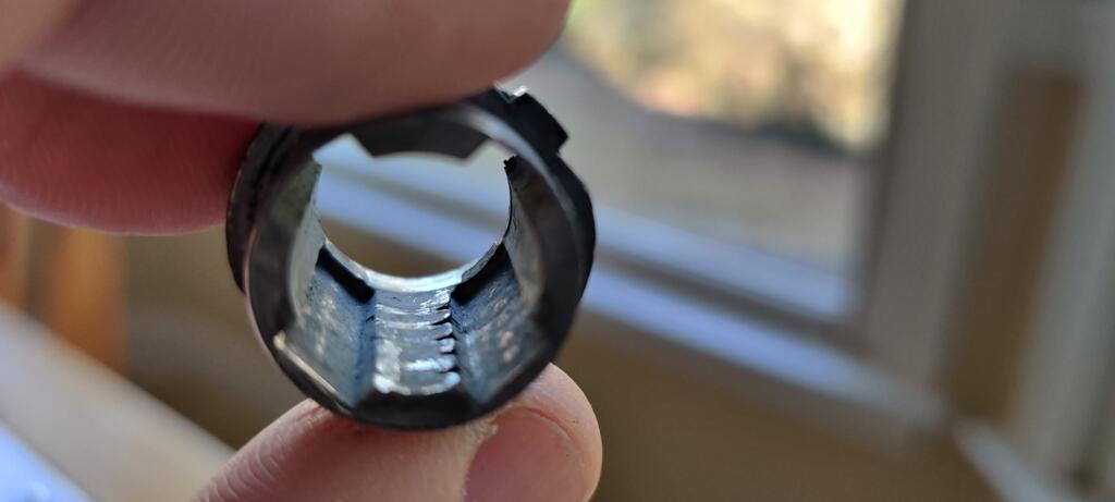
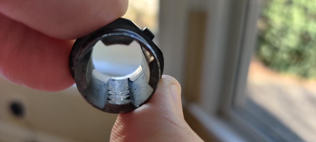
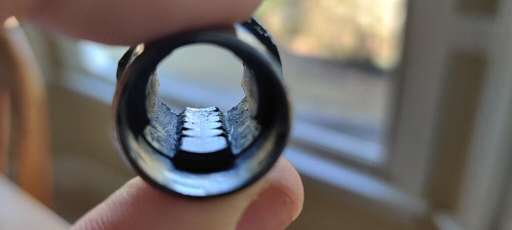
I didn't have the correct key, but got mine apart without much difficulty. The hatch lock clocks in two positions, one 90 degrees from the other. You have to align the wafers with a channel in the sleeve. Here are two photos showing the inside of the sleeve, one taken, and then the sleeve rotated around 180 degrees and another taken. Note the channels: The two channels in the first pic have "walls" at the far end. The other two channels do not - they are open channels from front to back. With the correct key inserted, the tumblers all retract, and pushing the large wafer in is all that is needed. Without the correct key, you may have to push the larger wafer down, and then insert a thin object like a hard wire that has been flattened to push all the wafers into the cylinder, so they will clear the "wall". Or, use it to push the wafers into the cylinder while you rotate the cylinder in the sleeve until the wafers fall into one of the channels without the wall. Then slide the cylinder out. The good news is that after you replace the wafers with the correct ones for a key you have, assembly will be much easier!


-
You push this special wafer in and slide the sleeve off the back of the cylinder. Do you have the original key for that lock? If so insert it into the lock and push the special wafer in and slide the sleeve off the back of the cylinder. If pushing this special wafer in isn't enough, then you may need to wiggle/twist the sleeve left and right a bit to free it up from the wafers in the tumbler (which could be snagging the inside surface of the sleeve a bit). I remember mine being a bit finicky. The inside of your sleeve may look like this: The wafers in the tumbler will grab... (hang) on the wear grooves a bit. So, you push in the special wafer, which when not pressed in sticks out far enough to keep the sleeve from sliding off the back of the tumbler. And rotate the sleeve left and right to get the wafers to align with the slot in the inside of the sleeve (and not hang on the wear grooves)

-
I suggest verifying that the engine is actually heating up beyond normal temps by checking it with a laser temp gun. After a complete restoration of my car, my temp gauge is reading higher than yours, but the temps at various locations on the head and thermostat housing are 175 to 195. I plan to remove the gauge and adjust it's reading by changing the position of a certain "adjustment" screw inside the gauge.
-
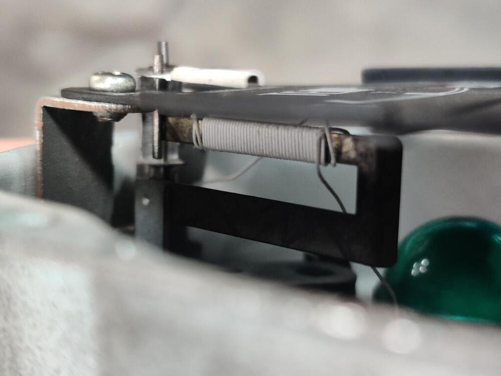
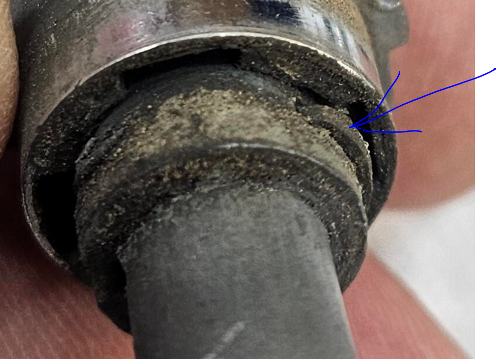
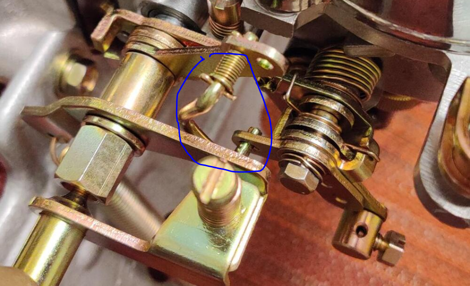
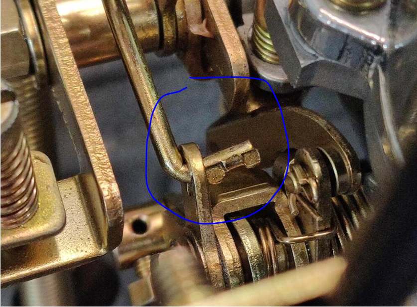
I started the car from dead cold a couple of days ago - this was after using the Uni-Syn to measure flow through each carb while the choke was in operation. I am very happy with how car starts now with the choke. I have also eliminated my sticking nozzles by bending the "Connecting Plate A". This is the flat bar part of the linkage that attaches to the bottom of the nozzle. Slight bends to it removed sideways force being applied to the nozzles. I had to do this for both carburetors. And, by setting the throttle plates firstly, to open to the gap specified in the factory workshop manual, and secondly, to achieve the same flow rate in each carburetor as indicated by the Uni-Syn flow measurement tool, I believe I have set the "starter interlock opening" on both carburetors very accurately, and I have achieved a well functioning "starting mechanism". The first step is to get the gap between the bottom edge of the throttle plate and the carburetor bore (as measured by a piece of ductile wire which I hammered to the right thickness and then used as a feeler gauge) to the .0232" to .0271" which is specified in the factory workshop manual. The second step is to start the car and set the "choke" lever to a spot where the engine is running at a fast idle speed (with the starter interlock acting on the throttle plates in the carburetors), and adjusting the "bent" connecting rod. This rod is circled in blue here: By bending it either more or less at the kink, you adjust its length, which changes the amount that this starter interlock linkage opens the throttle plates via the operating arm to which it is attached. When I was working on resolving my sticking nozzles a week or so ago, I managed to break the connecting rod on the front carburetor. I have since figured out what happened. When the screw holding Connecting Plate A to the bottom of the nozzle is removed, the starter interlock linkage (which is spring loaded) will forcibly move itself to a position where the bottom of this connector rod (blue circle in this pic) can shift laterally. In this picture, the rod on the rear carburetor has indeed shifted. It needs to be shifted to the left, so that the arm is located on the rod between the two pinched spots. The two pinched parts of the rod can align with the "key hole slot" in the linkage arm. When they do that, then the rod can shift out of its correct position as seen above. I did not notice this the other day, and when I couldn't bring the linkage back down to attach Connecting Rod A back to the nozzle, I just applied more force. The bottom of the rod had one of the pinched parts in the "key hole" on the attached linkage arm, preventing rotation at this joint. When I applied more force, this end of the rod twisted and broke. So, that is something to watch out for if you decide to work on your sticking nozzles!
-
I thread a transmission bolt into one of the bell housing bolt holes in the block, and one in one of the pressure plate holes in the flywheel, and then run some coat hanger or similar gauge wire around from one to the other and back again. About 4 loops. Flywheel is going nowhere.