Zed Head
Community Member
-
Joined
-
Last visited
Everything posted by Zed Head
-
There are several different perspectives someone might have about a project like that. Reverse-engineering, a forensic analysis challenge, a training exercise for the use of characterization instruments, even an example of a "green" technology. Or an early historical example of a wood-polymer composite. If you make it apparent that you're not profiting from the work the resistance to doing it for free will be minimized. It's a cool project related to a cool car. Guaranteed to raise interest. Even better, if a writeup of the work was done, shining some light on the university, everybody wins. I would make it clear that the main question is about the type of binder used. Is the binder a synthetic polymer or is it organically derived from wood itself? One is realer than the other but neither produces 100% "real wood". The issue of whether or not it should be called real wood will be irrelevant.
-
It's actually a Ringo song. Post-Beatles. By Hoyt Axton. He is a fascinating guy. Many bands covered his songs. https://en.wikipedia.org/wiki/No_No_Song A different Axton cover...
-
A chemist could separate the wood fibers from the binder and analyze the binder. It's not complicated and probably not too expensive. Infrared analysis just needs a tiny sample. Actually might not even need separating. A chemistry student at any research university could probably get it done for free. One path to knowing. Like counting horse teeth.
-
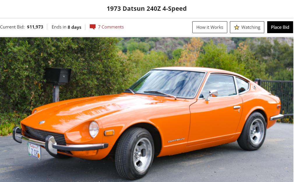
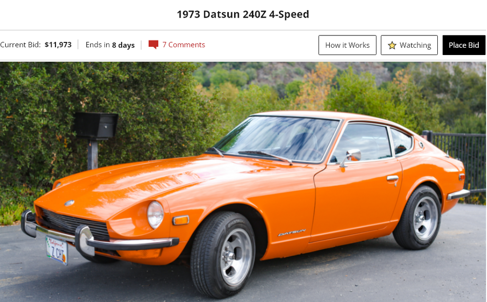
Well, that's kind of a bummer. The seller paid about $8,000 for 10,000 miles and a few years of fun. Not terrible, but not an investment either. In an ideal world, fun and profit would combine.

-
Just a nomenclature thing here - "resin" would be considered plastic. It is most likely a petroleum derived material, similar to what surfboards and boats are made from. Ultimately, the goal was to produce a product better than either wood or "plastic" alone. Wood feel, but with the dimensional stability and moisture resistance of synthetic polymers. It is wood AND plastic and better than either alone.
-
There are some forum members with large collections of used parts. If you have a specific need post on the forum and see what happens. Some of them will ship to Mexico I think. Also, many people would say to avoid California Datsun. Part quality is often poor, and returns or refunds are very difficult.
-
Cool. You didn't actually say why you were looking, for the record. Maybe you were thinking it. You just said parts were hard to find. Good luck.
-
Are you looking for more performance or for a replacement? Don't forget that you'll want a whole new set of rocker arms. Plus lash pads to fit the cam. Valve train work can get expensive quickly. Good luck.
-
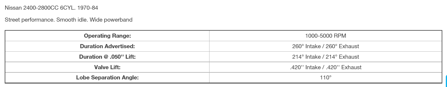
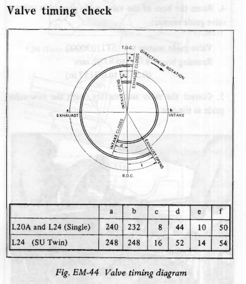
As Diseazd points out, those numbers aren't extraordinary. Looks like they extended duration but did not add any lift. Probably can't tell it from stock. Should work fine. https://www.jegs.com/i/COMP-Cams/249/84-123-6/10002/-1


-
I have mentioned in the past a method that I devised. Tie a long piece of thread through the hole in the clevis pin. Tie the other end of the thread to a piece of thin flexible wire. Poke the wire up and through the clevis pin hole in the pedal, pull it through with the thread, then pull the pin up to the hole by the thread as far as you can get it. Then use a screwdriver or your fingers to maneuver the clevis pin through the hole. The thread allows you to apply some pull once you get it aimed. My pedal box was mangled from a PO who had similar problems and must have taken out his frustrations with a hammer and pliers. And I still couldn't get my hands up there easily.
-
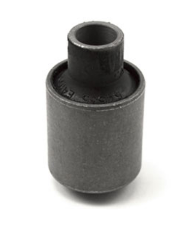
It's not a complex part. It just has to fit the hole and be strong enough to clamp the center tube of the bushing in place. Germany is metric. Looks like zKars gave the dimensions in post #2. Good luck. Merry Christmas.
-
Might be a flip or somebody just got tired of it. Purchased on BAT 3/7/2019. Now it's back. (p.s. it has 10,000 miles added since the first sale). https://bringatrailer.com/listing/1973-datsun-240z-224/ Previous - https://bringatrailer.com/listing/1973-datsun-240z-85/ Sold for $38,250
-
I'm no expert but I've always done one slow pump with the bleed screw open, close screw before end of pump, release pedal slowly so that the fluid can get in from the reservoir, repeat. Pumping 4 or 5 times doesn't really accomplish anything, I think. It might even force the bubbles in to solution in the fluid, from the pressure, or cause them to break up in to many small bubbles. Ideally, you want one big bubble sitting at the bleed screw opening, waiting to get out. Or, if I don't have a helper, I open the bleed screw, press the pedal down with a broken shovel handle through the driver's window, prop it against the seat at the bottom of the stroke, walk over and close the screw. Still a very slow pump. On the back I installed speed bleeders. They made a big difference. Again though, a very slow pump. Once the air gets out you want the hydraulic lines to refill from the reservoir, not suck back through the bleed screw or the bleed screw threads. Air has much lower viscosity than brake fluid. It moves fast.
-
Two common bleeding problems are having the bleed screws on the bottom on the front calipers, and having one of those disc brake swaps on the rear, with the bleed screw in a new orientation from the factory design. Air in the system shouldn't be affected by the booster. I mentioned the guy who sucked air in to the rear cylinder. Air will get past a seal much easier than liquid will get out. A description of your bleeding method might have a clue. Are you using a vacuum bleeder?
-
Kind of sounds like the MC was damaged when you ran it through a full stroke to bleed the brakes. Not uncommon, EuroDat has described it in past posts. Basically, for brakes, if you can pump the pedal and it gets higher and firmer it's air in the system. More bleeding necessary. If pumping does not work at all it's an MC seal problem. The MC pressure seals can leak without the MC having an external leak. If you installed a new MC it can still be bad out of the box. Today's aftermarket parts. p.s. I also just read a post on a different forum where a guy had a wheel cylinder that sucked air but did not leak fluid. Impossible to bleed.
-
This is what came to my mind also. Plug #4? It's a single cylinder problem. Changing things to fix one cylinder will affect the other cylinders. Also remember it has a performance cam. And it's a CA Datsun engine. If it was mine, I'd find a used stock unmolested engine and swap it in.
-
The colored links are just there for assembly. To evaluate wear you want to put the crankshaft at zero on the damper puller (TDC), tighten the chain on the tight side, then see where the notch is. Everything starts with the crankshaft. But, regardless, it will still run with the cam at 2. The torque curve will just be shifted to lower RPM.
-
Not sure what you mean by "slack". Choosing a sprocket position depends on the relationship of the notch and groove. A picture of the chain tensioner will give a clue on chain wear. No offense, but you're still working with a hodge podge of parts. But if it ran before it will probably run again.
-
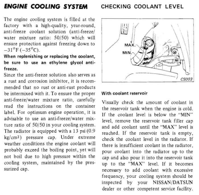
I have a Ford truck now and they completely changed the way the cooling system works. The reservoir is directly open to the bottom radiator hose. The pressure cap is on the reservoir, it's 16 psi on mine. Any bubbles that pass through the bottom hose rise up in to the reservoir. It's also called the degas bottle. There's a small hose on the top of the radiator that lets the fluid level in the radiator equalize to the level in the reservoir. When you see the fluid in the reservoir you're seeing the same fluid that is flowing through the system. No guessing necessary about level or fluid quality. It's pretty nice.
-
This was my point. The whole thread revolves around guesstimating. Always fun to discuss cooling systems though.
-
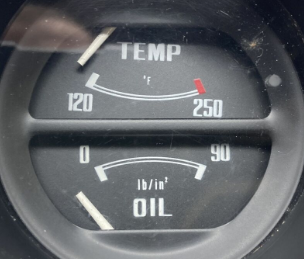
Take it out and run it and see if temperature keeps climbing or if it just rises and levels out. Fill up the reservoir first so you can see if the level changes. Here's a question though - how can you be so precise on the temperature?
-
Where did you get it? What do you know about it? Does it shows signs of being apart in the past?
-
Not sure why you can't just, as my father used to say, "get with the program". You're refusing to follow basic maintenance guidelines. The Z engines are fun learning tools though. You can do all kinds of crazy things to them and they just keep running.
-
Cylinder pressures at engine temperature are much greater than the leak-down test. And coolant gets sucked in due to engine vacuum. For a problem like yours, where you're on the edge, it would have been best to start with a properly filled and maintained system. You started with an empty reservoir, but didn't really say if it was ever full. Most of us never see any change at all in out coolant reservoirs. I have often wondered on my various cars if it was even working, the change was so indiscernible. If a change did happen it would have been concerning. Empty would be panic.
-
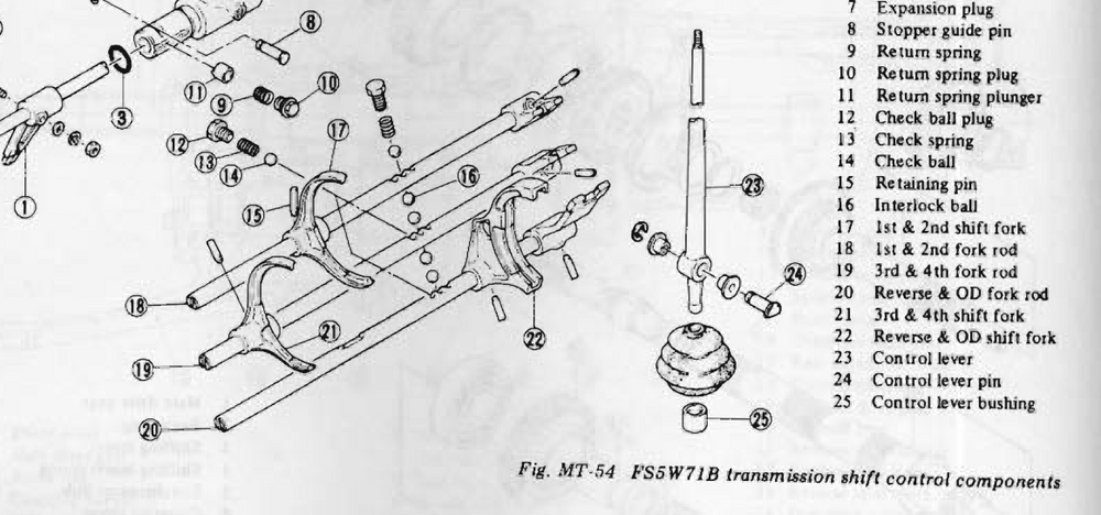
Not clear how this could happen considering how the system works. How does the end of the shift lever get past the 3rd gear rod fitting? The 3rd/4th rod should be centered and therefore in the way. I see roll pins. Maybe something is loose.