


Zed Head
Free Member
-
Joined
-
Last visited
Everything posted by Zed Head
-
 That's a popular one for the Z cars. There is info on the site about it. Here's one.
 -
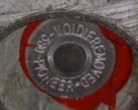
It's a rebuilt head, probably on a rebuilt short block. The N47 with flat tops would give a high CR. I don't think Nissan did that for their factory engines. Looks like somebody's home project. BRE probably stands for Big Ron's Engineering and Speed Shop.
-
the horn will make a horn noise.
-
The thing glued on with the red goop looks like a heat indicator used for rebuilt parts, to show that they've been overheated. BRE? Maybe Brock had a head ready for a race car and somebody ended up with it. https://bre2.net/the-racing/datsun/
-
https://bringatrailer.com/listing/1971-datsun-240z-178/?utm_source=dm&utm_medium=email&utm_campaign=2021-06-23
-
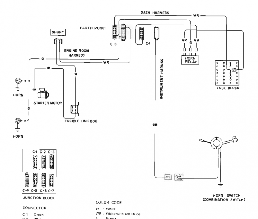
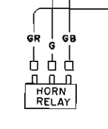
That is all correct. The power is used to actuate the relay, which then lets power through to the horns. The horn button always has power, that's why the horn always works, key on or off.
-
The diagram is not the greatest, they show power as starting at the starter, they left out the connection back to the battery positive terminal. Kind of incomplete.
-
Yes, the green wire is the ground wire for the relay solenoid. When you press the horn button the green wire is grounded, actuating the relay, which then passes power to the horns. You can take that green wire and touch it to a ground and the horns will get power. Honk.
-
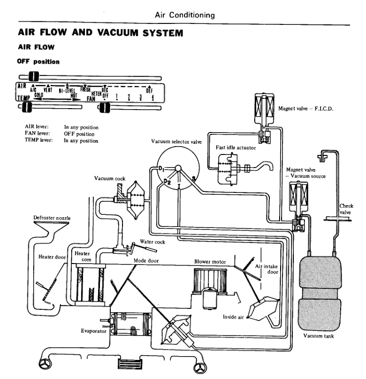
eBay would be your best bet. Or you could probably cobble together the valves and a vacuum bottle. Some of the valves, and the capillary tube, are probably non-functional and/or leaky, on your collection of old parts. You might be better off to get a more modern system. Here's one. Or at least part of it. There might be threads on the site about swapping a more modern control system in. Can't remember. https://zcardepot.com/products/air-conditioning-a-c-r134a-kit-260z-280z-74-78?_pos=6&_sid=687828280&_ss=r
It will work the same with either fuse.
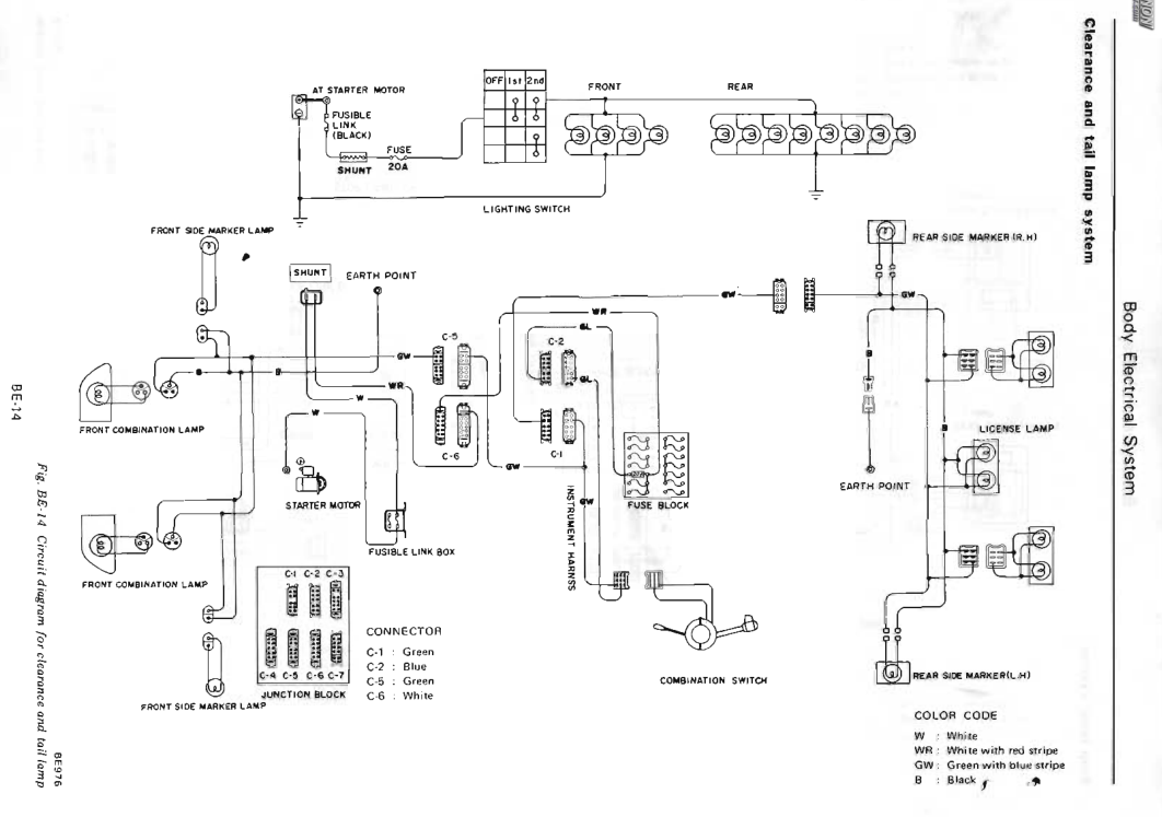
It's shown in the AC chapter. There are two solenoids (magnet valves) that control vacuum from a reservoir bottle that gets its vacuum from the intake manifold. This is from 1976.
 It's just been burned in to my brain by the fact that my parking brake would barely slow the car down no matter how hard I pulled. It would be useless in an emergency. On the other hand though, I had a friend with a 70's Celica (in the 70's) and another friend would grab the lever and lock up the back wheels while we were cruising down the road at 40 mph. Just for fun. So mine probably could have used some work. Still, it's designed for parking.
Just posting the links to fill things out. And, it's a parking brake not an emergency brake. https://www.thezstore.com/page/TZS/PROD/24-5151-1 https://zcardepot.com/products/parking-brake-cable-emergency-rear-240z?_pos=1&_sid=9d170309b&_ss=r
It's just been burned in to my brain by the fact that my parking brake would barely slow the car down no matter how hard I pulled. It would be useless in an emergency. On the other hand though, I had a friend with a 70's Celica (in the 70's) and another friend would grab the lever and lock up the back wheels while we were cruising down the road at 40 mph. Just for fun. So mine probably could have used some work. Still, it's designed for parking.
Just posting the links to fill things out. And, it's a parking brake not an emergency brake. https://www.thezstore.com/page/TZS/PROD/24-5151-1 https://zcardepot.com/products/parking-brake-cable-emergency-rear-240z?_pos=1&_sid=9d170309b&_ss=r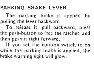 'posed to be. https://www.classiczcars.com/files/category/12-260z/
 C-5 or earth point.
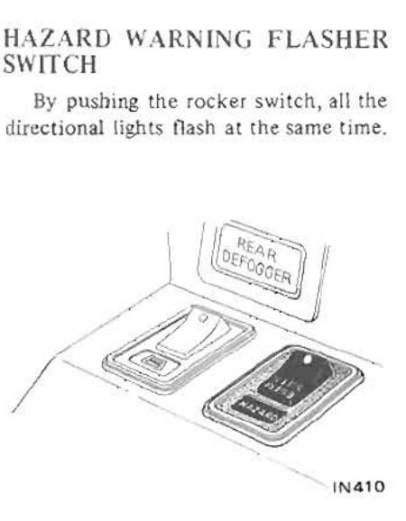
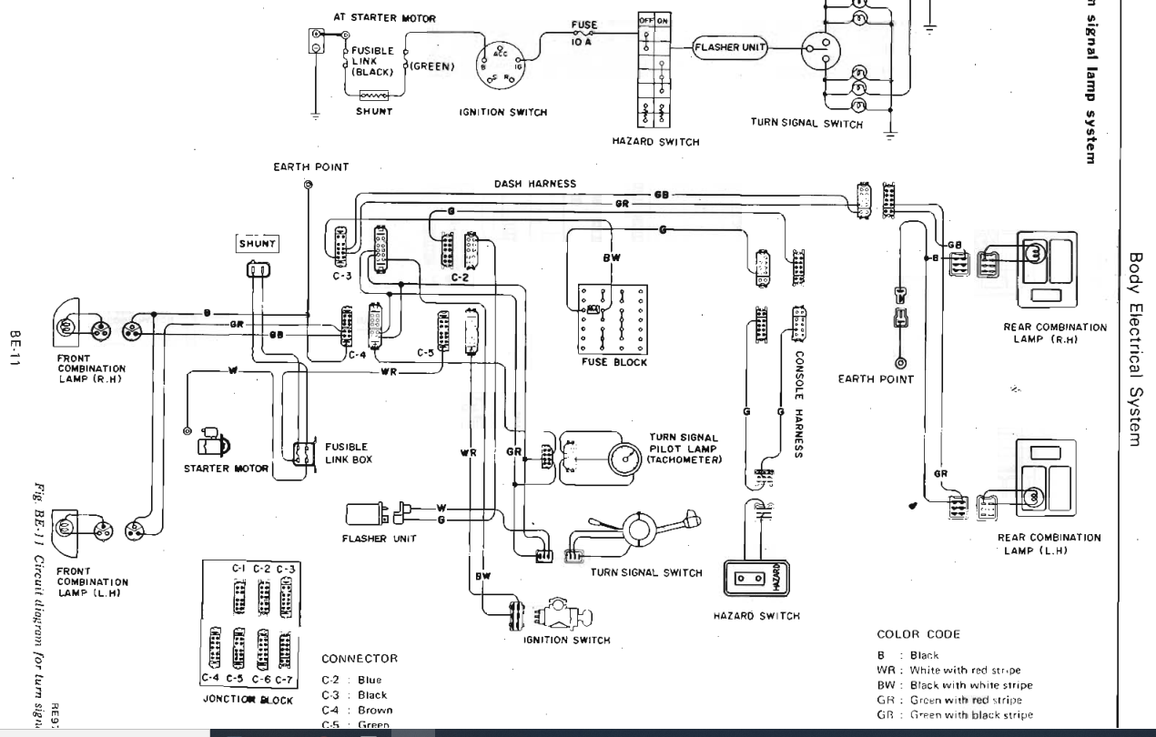
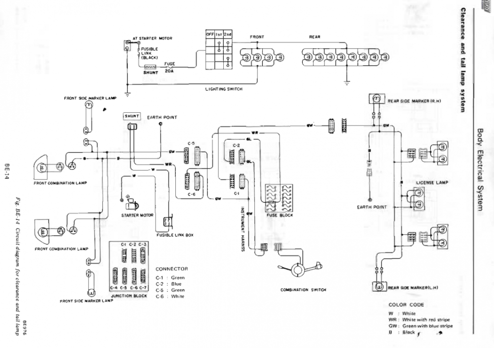 The Hazard switch seems to have some complex circuits inside, I've never had one part, but the Green wire seems to be involved. The switches get dirty inside and stop working. I'm going to guess that somebody was bypassing the Hazard switch. Does the Hazard switch cause the lights to flash?
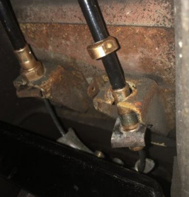
 Here's today's ZCD picture. Looks like they went to a one piece end as madkaw said. The old picture from hybridz is below it. Looks like MSA has the same vendor as ZCD used to have. Crimped/punched collars that slip off when used.
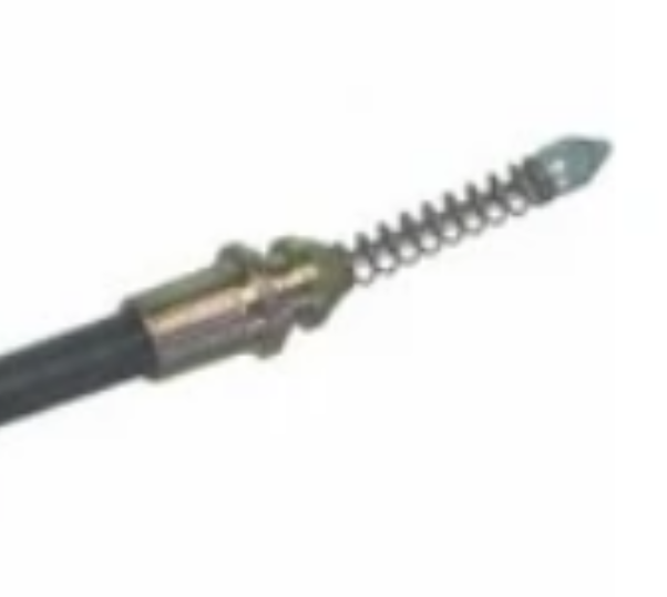
 You can @ them. @James@TheZStore @Joseph@TheZStore
I have the normal theme and it reads just fine. Looks like the others.
One down...
Can't tell which side of the harness you're looking at. Does it go in to the body harness or does it go to the switch?
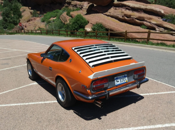
Interesting white trim ensemble and it still got over $31,000. No offense if the designer is a member. It's just different. https://bringatrailer.com/listing/1972-datsun-240z-177/
You can @ them. @James@TheZStore @Joseph@TheZStore
I have the normal theme and it reads just fine. Looks like the others.
One down...
Can't tell which side of the harness you're looking at. Does it go in to the body harness or does it go to the switch?
Interesting white trim ensemble and it still got over $31,000. No offense if the designer is a member. It's just different. https://bringatrailer.com/listing/1972-datsun-240z-177/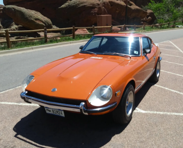
 The Hybridz thread was March of last year. Maybe ZCD follows the threads. He doesn't comment but they might have an effect. The forum concept is working!
Put one end on a terminal (link end) and the other end on a ground, like the block, or a body screw. With the key on you should get a light on all of them. You won't get a light (power) going across them unless there is a device turned on inside the car.
The Hybridz thread was March of last year. Maybe ZCD follows the threads. He doesn't comment but they might have an effect. The forum concept is working!
Put one end on a terminal (link end) and the other end on a ground, like the block, or a body screw. With the key on you should get a light on all of them. You won't get a light (power) going across them unless there is a device turned on inside the car.


Important Information
By using this site, you agree to our Privacy Policy and Guidelines. We have placed cookies on your device to help make this website better. You can adjust your cookie settings, otherwise we'll assume you're okay to continue.