


All Activity
- Past hour
-
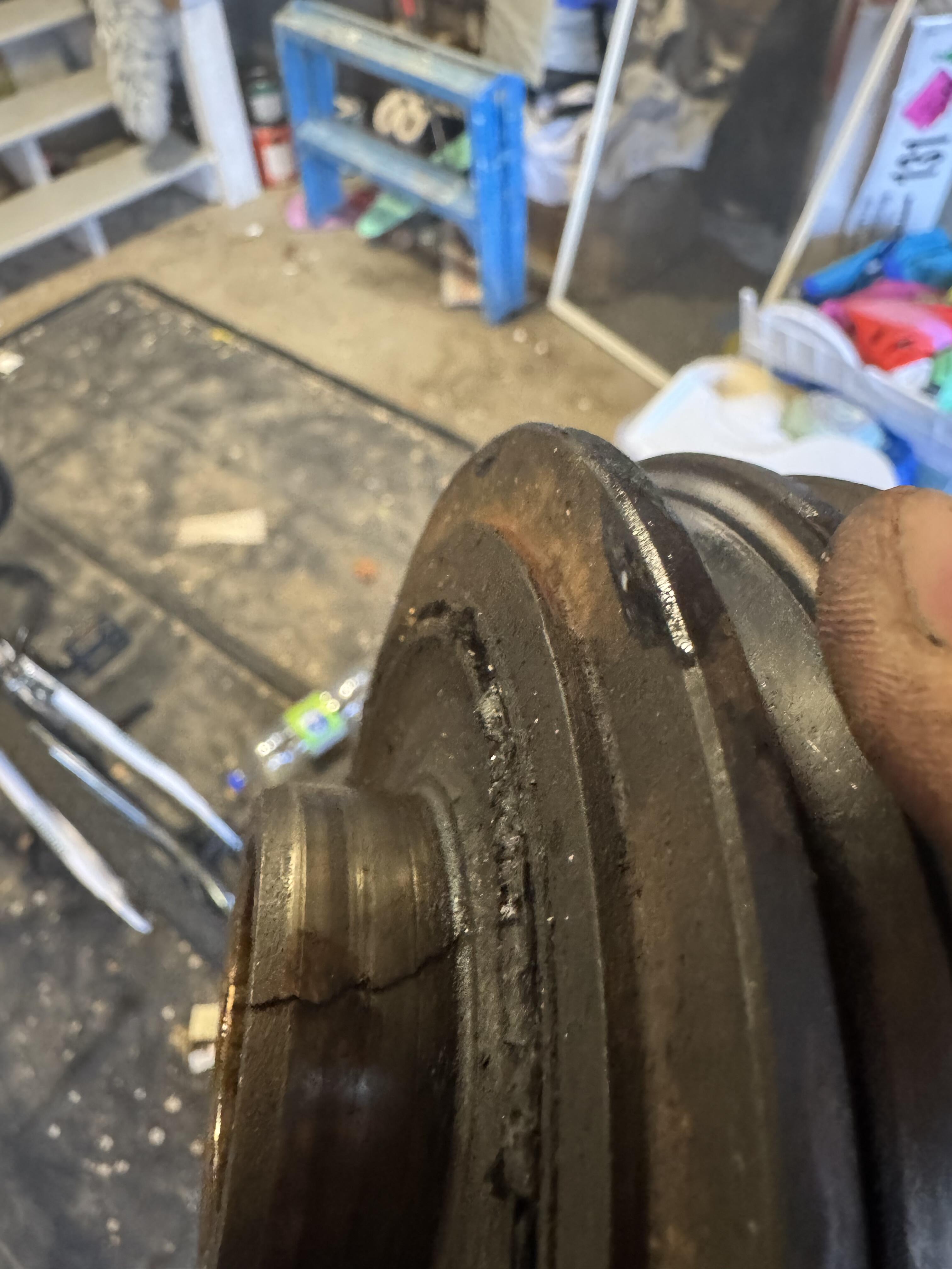
 Wow. Was it running like that or was during installation? How's the crankshaft surface? I think that new is avaialble. Z Car Depot IncSearch: 11 results found for "damper"New, used, and OEM repair and replacement parts for Datsun 240Z, 260Z, 280Z, 280ZX, and 510.
 -
 SWEET!! I like the “517” series myself.
 -
I was talking about a different problem. You'll know it if it happens. On the loose pins, if it was mine I might put a slight twist on every male pin in the ECU. Increasing effective width. I'd have to check the contact points to be sure it would work though. On to the next problem. Might as well get ready for the failing ignition module. It's a high probability.
-

-
 I was directed to this forum to see if someone has a harmonic balancer for sale in Canada. Possibly @zKars Mine has cracked
-
I'm right there with you. Hence the disassembly of the harness and connector head. I am very very confident at this juncture that it is something in the head itself...so either a damaged connector, or worn out connector, or bad wire-to-connector crimp/solder. It has to be one of these things. There just isn't anythinge else in the car that would be affected by my tapping on the ECU. "When you have eliminated all which is impossible, then whatever remains, however improbable, must be the truth."- Sherlock Holmes Wiggling the harness plug didn't do anything, almost certainly because it is so securely held in place to the ECU, and the ECU to the body. Tapping directly on the harness plug however had the most immediate and obvious effects. This is what made me think it was the "choke coils", their proximity to the most delicate "tap point", but that has now been elimiated. This leaves me with a "I'd bet $1000 USD" confidence level on it being something to do with the connector internals...and so I'm going to disassemble it and have a look. Since the pin receivers are where all the action is, I would think they would be the most likely culprit. I've unplugged the ECU only a handful of times in the 27 years I've owned the car...but who knows what the PO may have done. Now I'm all fired up. Maybe I'll do some re-arranging and find time during my evenings this week...
-
zzedisonzz joined the community
-

-
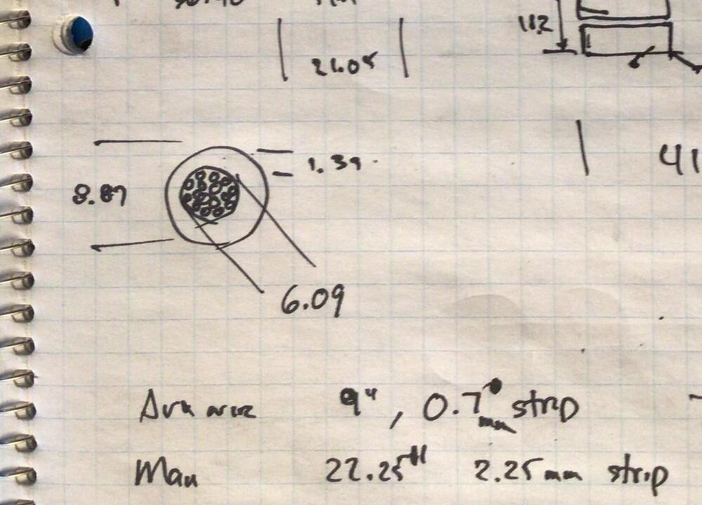
That would be great. Here's a clip from zKars notes. if I'm understanding the drawing correctly, he measured the wire diameter at 6mm (.24inch) and the insulation OD at about 9mm (.35 inch). I'm finding gauge numbers and wire diameters all over the place and am just looking for something similar.
-
-
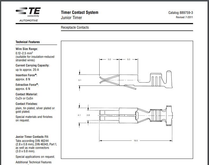
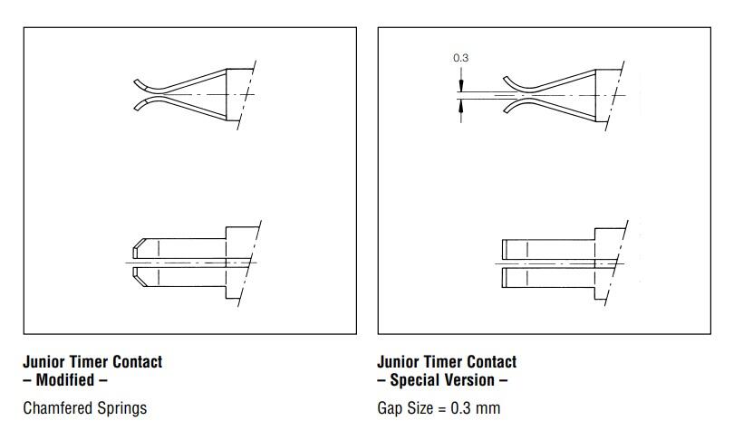
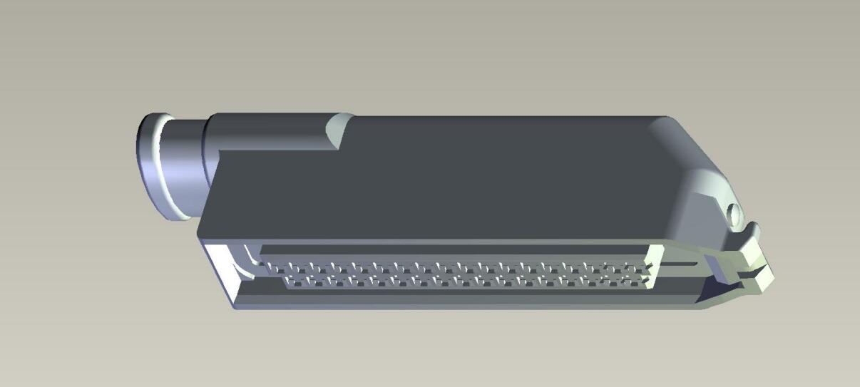
I think you would be surprised at the low amount of insertion force required to mate one of those female contacts onto the male tab. They do that on purpose because by the time you get to 35 of them, it adds up. So if you aren't 111% sure that you have a contact issue, I might keep investigating. But if you are looking to replace some contacts, i believe everything involved is old Amp (became TE) "Junior Timer" series. JT. There are many different categories within that family, but I believe the contacts used on the harness side are specially designed to be a lower insertion force. And yes... there should be a retainer tab on each contact. You should not have to worry about all the contacts come flipping out by accident. I think. ☺️

-
 Here are the original Nissan parts fresh out of their bags. Note the negative side only has the protective rubber cover. Yazaki was the supplier and their name is screen printed on the cables, just like on original spark plug wires.
.thumb.jpg.2d76a210cd295c389e788b3830b5df8f.jpg)
.thumb.jpg.da2f9756c9198b7cf0a6a1fbd2890b7b.jpg)
-
I don't think they are quite perfect @26th-Z there was no protective cover on the negative terminal on the early 240Z, just on the positive side to stop a short with the inspection cover.
- Today
-
 It has been a serious while since I was able to put some actual work in the car. I had some urgent projects on the house to complete, and then I managed to injure my hands, but now I'm back at it again. First, I had to re-install my tank. Since I sold my new fuel tank including rubbers and straps at the Japanclassic, to help somebody get is car running again quickly, I had to wait for a new one to arrive from S30.world. Unfortunately, new straps are currently not available anymore, so i had to go through my set of existing straps to get the best ones for temporary usage: First i had the rubber insulator blocks installed on the tank: And then had it all wrapped to avoid scratches on my brand new tank: And then everything installed. Thanks to my new transmission hoist, this was a lot easier than last time. And last but not least, i had the drain plug installed, which comes with the tank: Next? Front end work. Ever since I had my wobbly bent EU spec front spoiler installed, I was wondering myself which route to go. EU-spec corner valances with the mounting holes for the spoiler, but no holes for the Lower turn signals or other way? After thinking about it for a while, i decided to take the best of both worlds. Some might call it sacrilegious, but I decided to go what appeals the most to my eyes. US spec lower turn signals, but EU-spec front spoiler (which also helps stabilize the car and is not just for the looks). My original thinking was that the US-spec corner valances need to be modified with that "loose-nut" mounting brackets for the lip, but when checking my EU-spec valances, i realized that on the corner valances (unlike the center valance) there is only a simple hole. So the modification of US-spec valances to fit the EU-spec spoiler is simply to drill a 5mm hole in the right place. To get the right place, i made a nice little template from tape. Transferred it from the EU- to the US-valances, and drilled / cleaned it. Unfortunately, I found that on the LH-side somebody had previously drilled holes in the wrong places, for whatever reason. Probably they had some different spoiler installed? I'll leave that to the bodyshop. So everything set to install the spoiler completely? Almost. As you can see, the brackets on my worn out spoilers are quite bent. Some were even completely missing or "fixed" with a bit of backyard-engineering: After I bent all the existing brackets in a more-or-less correct position and installed it back on the car, i have to admit it looks quite good, even though it's still just a completely temporary mock up. I also had my replica US-spec turn signals installed (I will look for some good OEM-ones, as these lack the mandatory E-stamps on it). Which made the iconic, but also a bit ugly, EU-spec turn signals obsolete. Even though I don't think the look is too bad, I always have the feeling that they were just slapped on the car in a hurry, and are held on the bumper with only one nut, so they always look a bit off in their position and are hard to get it right (see previous photo). So I had them removed. The US / Japan spec turn signals always looked much sleeker to me, fully integrated under the bumper. Like intended from their designers. So for the moment, I'll stick to this setup. But I might change back to full EU-spec, if required. During this work, I was also able to fix two previous issues with the front bumper alignment, which is great too. From my point of view, the front-end (everything in front of the radiator support) is completed now. Next I'll focus on some other points. My 2-do list is getting smaller, and I'm happy with every task I can check off. I expect DHL ringing on my door with some nice stuff from Japan every moment, and i have some more things on the way here, so expect another update soon.
 -
I'm generally familiar with the brown-out condition the Z's ran under due to an undersized alternator or so it was explained to me when I replaced my headlight switch assembly... I addressed that a couple decades ago by installing a high output one. Also, during the pandemic, one of my projects was to convert the entire car to LEDs (minus the headlights), which dropped about 200W of load off the electrical. The headlights I was planning on doing very soon...but now that is clearly on hold until I have a drivable car again. ;)
-
 Steve at '240zRubberparts' shows a reproduction cable set as out of stock but they are available on the bay for the same price Steve was asking. I bought a set a long time ago and they are perfect. eBayDatsun 240Z Reproduction Battery Cable Set | eBayAt long last! A hand-crafted reproduction of the original style Datsun 240Z battery cable set. We've all waited a long time for this. For those of you who pay attention to detail and want to add th...
 -
Not 111% certain on root cause yet, but 100% certain it isn't the ECU (cold solder joints or otherwise). The problem was very reproduceable previously by hitting the ECU hard enough at any time, not just when warm. During testing, I BEAT on the ECU with zero effect. What I did not do is whack the actual harness plug as planned, the pins simply were not secure enough. They did not slide out on their own, but any brushing of the wires in-situ would likely have caused them to slide out or lose contact. They were simply not tight at all. If you look in the photos closely you will see I have a rubberized tie-wrap wudged between the dual-bank wires to help them maintain contact. I don't have an official "pin drag" tool, nor do I have any pins that are the precise size of the ECU pins, except on my spare ECU...I tried a bit of googling about Bosch 35pin connectors to no avail but may revisit that. I should note though that the blade connectors I used are definitely thinner than those on the ECU. I had to really really push to get the female ends of the extensions on the ECU vs the harness connectors that could have been pushed in by an ambitious ant. At this point I have removed the 3 miles of electrical tape wrap that was over the rubber harness covering all the way down to the harness head. I did not have enough time to figure out how the harness head disassembles, so if anyone has one laying around and wants to give me some pointers that would be great. I've not had any time to give it a close look yet. The best I found was one for sale on EBay that has some useful photos. I have a large array of spudgers and other disassembly tools, so I'm sure I can get it apart, but it is always nice to have a look at the inside of what you are working on first. Old plastic is old. My biggest concern is that the problem might be an internal break in one of the wires that isn't discernable externally. Hopefully not though, all of the wires under the tape/rubber look like they were installed yesterday; they are that fresh and new. There is even some marking paint on them that is still pliable; mummies were less well preserved before burial. Another concern I have is when I get the casing open that all the individual connectors come flying out, leaving me to do wire-tracing to re-identify their homes. Hopefully they have individualized stays that are still in good shape. I don't know how I will tighten up / micro-crimp the female leads or if I will simply replace them. There isn't a lot of play in the harness so I am loathe to cut them shorter to get new ends on. I don't even know what these types of ends are called or if they even have a special name. I think they are the same as an injector plug and I have several spares of those, so next weekend I'll look into that. The adventure continues...
-
 Wholesale Canadian changed their profile photo
 -
Wholesale Canadian joined the community
-
Do you want me to measure it? You'd be amazed the stuff I've found on EBay and Craigslist!
-
For the record, I just read that zcar.com thread and see that I might have actually borrowed the transistor replacement idea from ZXPastor. Not sure. I got the replacement transistors at a Fry's Electronics store before they shut down. Cracked solder joints aren't uncommon on the old Datsun electricals. The headlight and running light connections, on the top of the steering column, crack and break also. You might add some relays before those fail. Full lighting circuit current runs through them. They get hot. Will be following to see how things work out. You'll have three ECUs to swap in and out for testing and comparison. Good times.
-
So... While we're here. Anybody have an educated guess as to the gauge of wire used in the original cables? The common choices here in the US are 4-gauge, and 2-Ga. You can get others, but those two are the most common.
-
There goes Roo again showing off his ebay prowess. Your kung foo is the best.
-
-
-
 I really, really want one of these. If my 289Z were fully restored and I had no need to spend money on it, I would definitely get one.
 -
Don't overlook that when you have the connector disconnected from the board that the solder joints are probably less-stressed. I didn't see the common cracked solder joint problem mentioned in the thread. For some reason the internet is not picking up the old threads when I search. I only came across one. I've seen the others though.
-
RESULT: Loose harness connector(s). Now to figure out how to either tighten/tweak the harness connectors...or replace them 🫤 There is still a mystery (to me, at any rate) on why the engine would sometimes simply shut off like a switch and sometimes stutter-stop, and why sometimes it would re-start immediately and othertimes re-start 10-20 mins later. My hypothesis is that by simply getting in/out of the car while diagnosing I was re-wiggling the loose connector(s) such that they had good-enough connections, and the changing fault symptoms were a result of different pins or a different combo of pins losing contact. The end result is the same: Fix all the connections and do pin-drag tests on all of them to make sure they are sufficiently grabby. Thank you to everyone. I hope it was fun for you too.


.jpg.6a7ee9596ce0a8e3482d42779bbb3892.jpg)
.jpg.ac5d0880366baaf14fda79c9b3a6419a.jpg)
