

Clock replacement for 240Z (Quartz)
Entry posted by Mikes Z car
2,121 views
Hi all,
I got a quartz clock from Michael's (arts and craft store in USA) and replaced the mechanical clock mechanism in my 1970 240Z (my clock face says JECO). There is a thread where someone else used this same clock for their Z, the following is my experience. The easiest way to do this IMO is to use the hands from the new clock and to wrap wires onto the new clock battery connections to remote the battery location to perhaps the fuse box. I didn't install that way as I wanted the clock hands to look stock and I prefer soldered connections.
Materials needed:
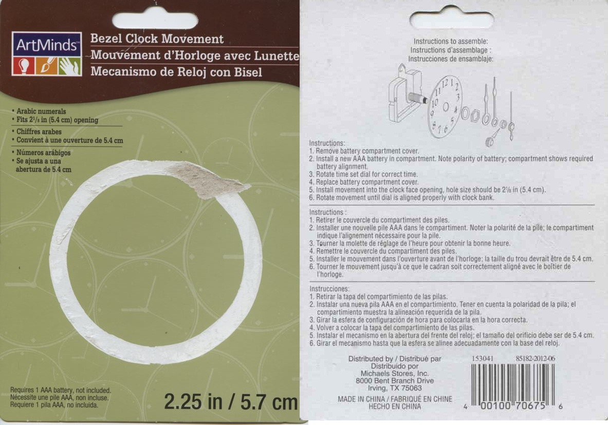
A Quartz clock from Michael's ($18), see pictures of clock card for model
B Battery holder for AA (or AAA) battery from Radio Shack
C Small wire to run from clock to battery holder
D Epoxy glue
E Glue gun to put a dab of glue on inside of set time knob
F Optional tape to cover three bolt holes in back to keep light in
G Bench grinder, dremel or possibly sand paper (to remove raised edges on back of clock face and hour hand)
H Soldering gun if soldering connections
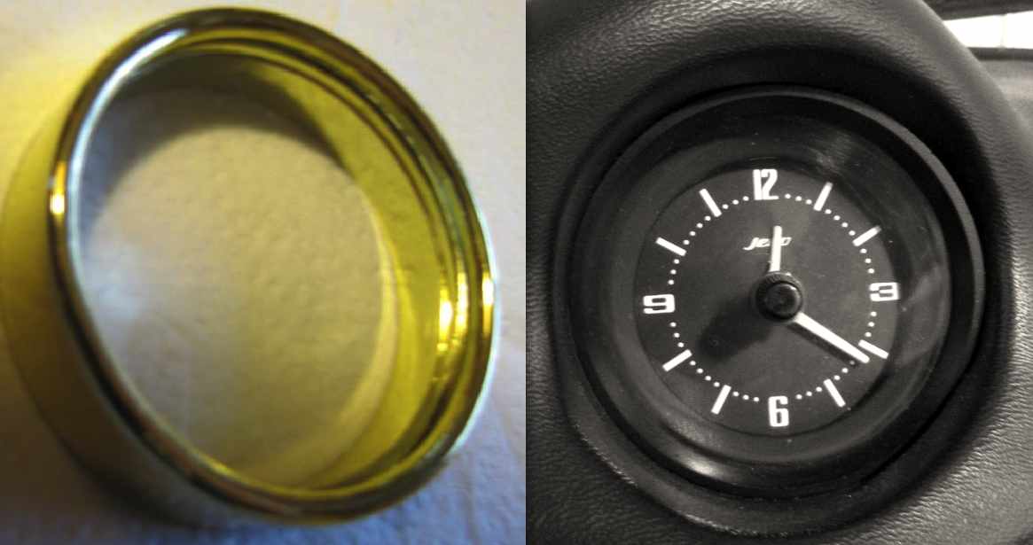
1. I ran the new clock for 24 hours verifying accuracy. Michael's clock front bezel and final result:
Bezel (not used):___Final result:
Clock card from Michael's:
The existing clock can be taken out through the heater fascia panel or glove box. Thread on removal:
http://www.classiczcars.com/forums/help-me/46462-new-clock.html?highlight=liner
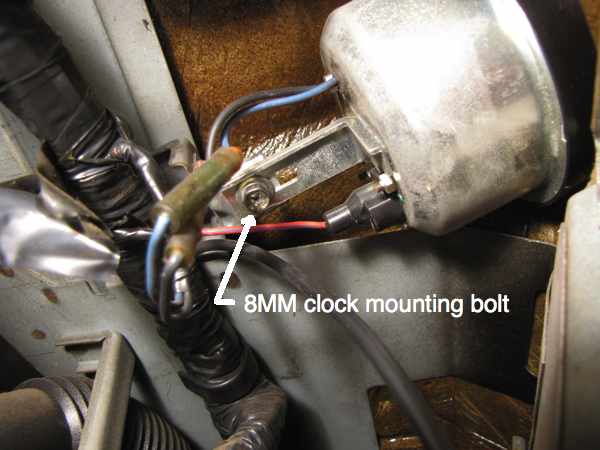
Also see clock threads listed below. I went through the heater panel as it was already open for other work. Per these clock threads some 240Z clocks have a bracket for mounting, mine doesn't seem to have a bracket. My clock was held on with an 8MM bolt that is also a phillips head. I had to use a nut driver for more leverage.
2. On back of the clock I removed the three small nuts. I also removed the 2 screws that hold the two clock halves together. I cut the wires for the motor off the back of the clock.
3. I pulled off the Z clock hands but had to gently use a small screwdriver from the side to persuade them to come off. Screwdrivers can be covered with tape to prevent scratches. Inadvertent scratches can be marked out with a black marks a lot.
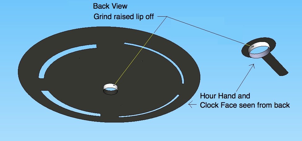
4. I covered the 240Z clock face with a ziploc bag I cut a slit in to go around the center hole by taping it on both sides of the thin aluminum face to protect it though thin cardboard might have been better protection however I didn't damage anything. I did not tape directly to the front of the clock face to avoid marks. After removing the hour hand from the 240Z clock to prepare it for re-use I taped the front of it to a piece of cardboard to expose the raised edge to discourage it from taking off while using the bench grinder on it. I ground the raised edge flush on the back of the face and the back of the hour hand. The minute hand didn't need modification.
Front view:............................Raised edges on back to be ground off:
5. I epoxied the new clock movement around its edges onto the back of the face making sure to get the post for the hands centered in the hole on the face. Epoxy wanted to let the new movement slide out of position so I re-centered it a few times as it dried.
6. I wanted to re-use the 240Z hands but they have mounting holes that are too big to fit tightly on the new movement so I epoxied the 240Z clock hands on top of the hands on the new movement from Michael's. To make that possible I cut off about 1/4 inch of the minute hand on the new movement as it was too long and would have been been seen sticking out from under the end of the stock 240Z minute hand.
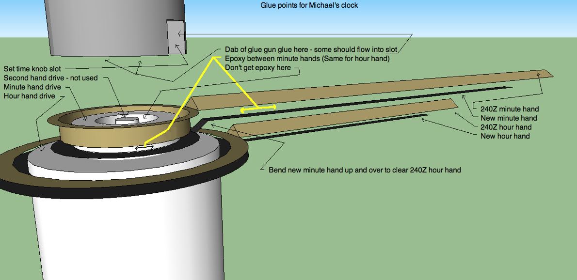
On both hands on the new movement I ground off part of the sides of the arrow on the ends of the hands as they were wider than the width of the 240Z hands and again would have been visible once the clock was placed into operation. I had to be careful here as the new hands are thin aluminum.
7. For the battery connection I could have wrapped wires onto the existing battery holder which would have been much easier than what I did. An idea here would be to wedge the wires in the battery compartment with a wooden dowel cut to the size of an AAA battery and maybe glued in. Another idea might be to solder the wires to a small piece of flat copper with the flat copper wedged in between the battery connections and the wooden dowel. See * below for how I did the connection to the circuit board.
8. I pressed on the hour hand from the new movement that had been prepared to be physically smaller so it would hide under the 240Z hour hand. Next I epoxied the 240Z hour hand that had had the raised edge removed on top of it. The edge would have raised the hour hand to a height to where it would not have cleared the minute hand I was about to install. The 240Z hour hand wanted to slide off center so I had to recheck it periodically as the glue dried. Five minute epoxy might have worked better.
9. To install the minute hand from the new movement I put it over the already glued on hour hand to check for clearance, I needed to bend the minute hand up and over the hour hand assembly using tweezers for the bending. I applied epoxy to the 240Z minute hand with a toothpick to make sure I didn't get too much that might flow into the second hand mount point (not used) in the center of the new clock post to avoid having it bind. After gluing the stock 240Z minute hand I had to recheck it periodically as the epoxy was setting to check for centering and to make sure it was sitting flat with respect to the face. I put a toothpick across and on top of the minute hand at the post it was on with a small weight on the toothpick with a spoon to hold up one end of the toothpick with the idea of keeping the minute hand flat and centered on the post so it would look right.
10. For the time setting function I put a small dab of glue gun glue on the end of the set knob next to the minute hand (a thread mentions using a glue gun). This was to make the set knob reach further when pushed in to contact the 240Z minute hand that was glued on top of the new movement minute hand. I made sure to get the glue down in the slot at the end of the setting knob to secure the glue better. Too much glue can be trimmed with an ordinary finger nail clipper. I think the end of the glue dab needs to be fairly flat. Not enough glue and the set knob when pushed in won't contact the minute hand making setting the time impossible, too much glue and the knob will bind the minute hand possibly stopping operation of the clock. One other thing I did to further secure the glue dab was to take a toothpick and apply a very tiny amount of epoxy to the junction between the dab and the set knob. I used jeweler's magnifying glasses to make sure I didn't glue the set knob so it wouldn't push in.
11. The end result is that the clock looks great installed in the car and is keeping good time.
Here are threads on fixing Z clocks:
Zclocks good quality:
http://www.classiczcars.com/forums/thread5093.html
Keep hands from new clock:
http://www.classiczcars.com/forums/open-zcar-discussion/48910-clock-redo.html
Getting clock out thru glove box (tends to destroy glove box) or heater panel:
http://www.classiczcars.com/forums/thread9492.html
Different kinds of clocks described-motor type-pendulum type:
http://www.classiczcars.com/forums/thread18442.html
Fixing electric circuit type clocks:
http://www.classiczcars.com/forums/thread22795.html
Replace with desktop auto car parts store clock -orange face:
http://www.classiczcars.com/forums/thread36393.html
Replacing capacitors on clocks that use them sometimes helps:
http://www.classiczcars.com/forums/thread18851.html
Zclocks and Auto Meter clocks discussed:
http://www.classiczcars.com/forums/thread13723.html
Clock runs when car runs but then quits a few days after car is parked:
http://www.classiczcars.com/forums/thread12992.html
Changing out mechanical movement to quartz discussed, radio shack 12 volt to 1.5 volt regulator mentioned:
http://www.classiczcars.com/forums/thread10767.html
Oiling original mechanical clock sometimes works sometimes doesn't:
http://www.classiczcars.com/forums/thread7817.html
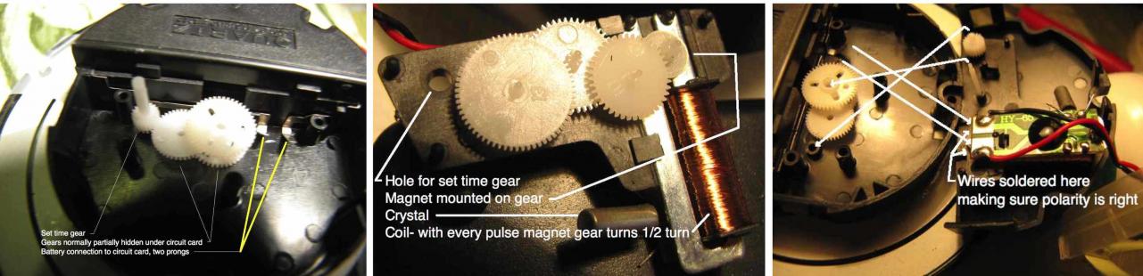
* I tried to solder to the connections in the battery holder but the solder would not stick. To solder directly to the circuit board I took the movement apart by unscrewing a screw and unsnapping the two plastic latches on the sides. I soldered the new battery wires directly to the circuit board where the existing battery holder connects VIA a spring like action by two prongs (The prongs aren't soldered). I scraped off the two circuit board "pads" with a pocket knife where the two springlike prongs connected and got down to a copper colored metal which my solder gun could solder to. The wires I used are very small 30 gauge, they need to be to make for easy soldering to the small pads and to make it easy to get them to pass out of the movement though a small hole could be drilled in the plastic case of the movement for the wires. I personally feel taking the movement apart and getting it back together properly was not particularly easy as there were several very small plastic gears that kept falling off and I had to remember where they went.
Clock innards:
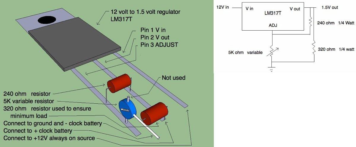
12. **** How to get rid of the AA battery: ****
Schematics below include the 320 ohm resistor needed for quartz clock per spec sheet for minimum load of 4 mA. Be sure to adjust the 5K pot for 1.5V out before connecting clock.


4 Comments
Recommended Comments
Create an account or sign in to comment
You need to be a member in order to leave a comment
Create an account
Sign up for a new account in our community. It's easy!
Register a new accountSign in
Already have an account? Sign in here.
Sign In Now