240260280z
Free Member
-
Joined
-
Last visited
Everything posted by 240260280z
-
 http://www.cnn.com/2012/05/29/tech/innovation/ketchup-coating-mit/index.html?hpt=hp_t2
 -
-
I have been meaning to update this article with tuning guidance following further study on a side draft forum but the data I have so far is inconclusive. I have a set of Webers here that I will experiment with once I break in a resto's engine. One of the problems I found in working with an experimenter on the side draft forum is that the accelerator circuit leaks fuel all the time and it lowers the air:fuel ratio. I speculate that the engine vibration shakes the weights and allows fuel to pass AND there is a vacuum at at accelerator circuit's nozzle at partial throttle as the top of the throttle valve approaches the tail of the main venturi. This leaky accel. circuit makes tuning more difficult. At present, here is what I would do with Weber DCOE's to tune. 1. plug inlet jet/ball valve leak back to accel. circuit at bottom of fuel bowl. 2. set throttle linkage so that valves are covering the first progression hole. 3. remove main jets. 4. experiment at low rpms and tune the idle circuit for idle and low rpm operation 5. install the mains and tune for high rpm and WOT performance 6. install the accelerator circuit jet/ball valve AND add springs to press the weights down OR replace the weights with springs. 7. adjust the accelerator circuit for slow and fast RPM transitions You will have to wait until I get Mikunis. My next project will be ITB's and Mega squirt. FYI here is data from my friend showing the AF ratio and proving a leaking accelerator circuit. (plugged vs non-plugged during slow accelerations (2 min.) to prevent activating the accelerator circuit). This test was repeated 3 times. The red numbers show the change in Air:Fuel Ratio at each corresponding RPM. Here is where I think the vacuum pulls on the accelerator nozzle and causes the greatest fuel leak at cruise:
-
I did ~ 4min with a sand flapper on a drill + valve grinding paste and another 5 min with a brake hone without and without grinding paste... it still does not fit however it is a bit looser for the first 3 or 4mm before it jams. I am getting worried that I may not have a flat face now that I have done so much with a hand tool. This is complete BS how MSA and Powerforce can make and sell ****.
-
BAD DOG is great!
-
In racing bicycle metal tube design, studies found that tubes can be thinner in the middle of a span to save weight and not sacrifice rigidity and strength in a significant manner, as well, some designs had the main tubes of aluminum and the rear triangle and forks out of chromoly steel to maximize strength. Some early aluminum bikes has all aluminum components but flexed like crazy and broke, later designs used larger diameter tubes to increase strength. I assume the same studies and experiments must be done for automobile tube implementations but it is hard to dig up.
-
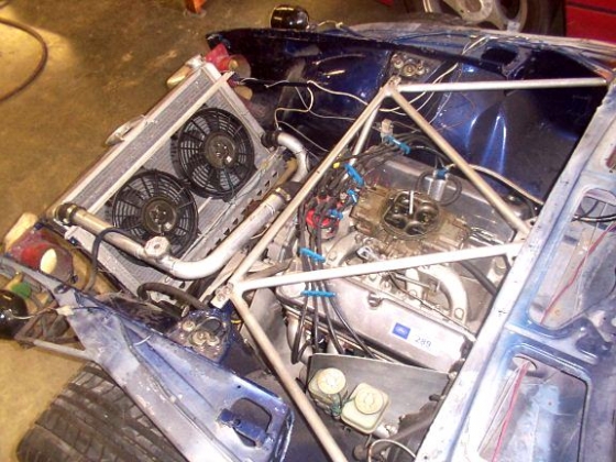
Hi John, I was referring to simply looking at what others are doing via online pictures. The fundamental static engineering rules I refer too are what one learns in an entry level engineering course: loads, torques, etc. in bridges, trusses, towers, etc. The general rules are: straight sub-members and triangle geometry whenever possible. In looking at online photos of other's work, I saw things like a crossbeam through the dash is not one piece but rather complicated into two that were angled where butt-joined, I have seen many "almost triangles", overly complicated dips in door areas, over gusseted, non-gusseted, too many sub-members, not-enough sub-members. I know it all depends on the application, rules, and personal taste however, it got me thinking that there must be an ideal optimized configuration to start from. I just went through this page and it seems to parallel with the core of my question however they show many cat's to skin: http://www.erareplicas.com/misc/stress/deslogic.htm Here is another easier question: "What is the best design for an off-the-shelf engine compartment reinforcement assembly?" Here are some examples, however which gives? 1. Most stiffening 2. Lightest weight 3. Best stiffening to weight trade-off and How does tube diameter, tube wall thickness, internal butting, and mounting point method affect stiffening and weight. The best geometry may be useless if it attaches in a weak manner or in an inappropriate location. A Lightest, no curve in cross member B Big gussets, almost triangle, cross member curved in middle to clear motor,small strut-tower mounting plate C Little gussets, two little triangles, cross member curved near ends to clear motor, large strut-tower mounting plate D No gussets, three triangles,no curve in cross member


-
I have seen ~4 heads with cracks in-line with the location where the runners are anchored into the head. My speculation is these cracks result from thermal cycling of the steel and aluminum and their different thermal expansion rates. Or, from overheating (high exhaust gas temp) and their different thermal expansion rates. Nothing you can do about it.
-
This is done all the time with bike frames, I wonder if anyone has done an actual study for Z cages? The strength/rigidity to weight would be optimized by Tube dia. vs wall thickness vs geometry for a z. I think once an optimized basic design/configuration is found for these two items (strength & weight) then this basic structure can be tweaked for: 1. compliance with rules 2. ergonomics 3. safety I started looking at images of cages online but so many break fundamental engineering rules of "static structures" that I decided to post this question. I guess another option would be to clone BRE and BSR designs but I assume computer modelling has come along way to better their designs? (It certainly has for bikes).
-
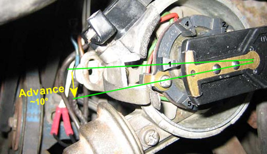
Just get the crank at TDC and the distributor's rotor should have just swept past #1 CCW ~ 10 degrees (advance).

-
I am now looking at this same detail. I think that rather than buying a new mount, one should be able to loosen the oil pump, rotate the distributor spindle, to make any mount work in its sweet spot.
-
Perfect! Thanks for your help.
-
Where does the forward end of this spring (#23 in drawing below) attach to the linkage? I can see the hook welded to the body for the back end of the spring.
-
Lithium grease in a spray can works great for lube. Not sure if it drys out over time but it is easy on the rubber/urethane.
-
Labour of love.
-
I ended up installing the engine and transmission together as one with two friends and an engine lift with tilter/balancer. I installed the clutch and transmission with the engine hanging on the lift.
-
Installed clutch, transmission, then motor.
-
Rebuilt a breaker plate. Sorry no pics. Buttery smooth... also rebuilt the rest of the distributor.
-
I have 3 cranks: L24, L28, and LD28 Neither of the 2 MSA untis fit. My stocks damper fits all 3. On the MSA unit, even the woodruff key does not fit in width or depth. I wasted $350 on these POS. I just checked,and the MSA website now says to buy the part then take to a machine shop to make it fit. BS!!! .
-
Thanks! I bought two and two bolts and $$$ for shipping to Canada. MSA suck for selling this ****. B@stards!!! What a waste of time and money.
-
Thanks guys!
-
Bought it plus the $$$ bolt Does not fit. I searched Zcar.com and found one post where a guy had to get it machined to fit. I am thinking of boiling it in a bag on a Coleman stove where the car is. All suggestions welcome.
-
In best way I mean, reducing chance of smashing stuff/chipping paint and ease of lining up parts. I have engine hoist. 1. Transmission first then motor 2. Motor first then transmission 3. Motor and transmission together (I did this before with a friend but I am thinking it may be challenging for 1 person.)
-
Well I think you are north of Anchorage so you beat the Z's there....and you may be north of Fairbanks however, I hear that St.Nick. has a Z.
-
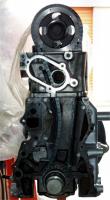
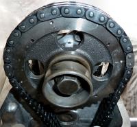
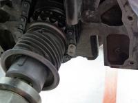
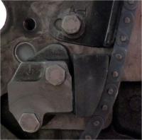
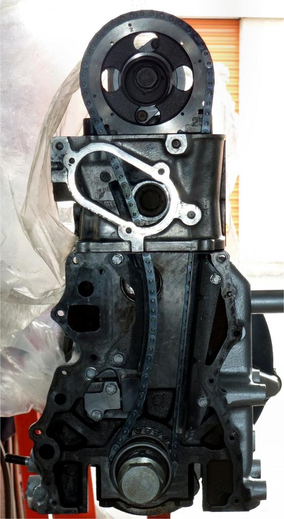
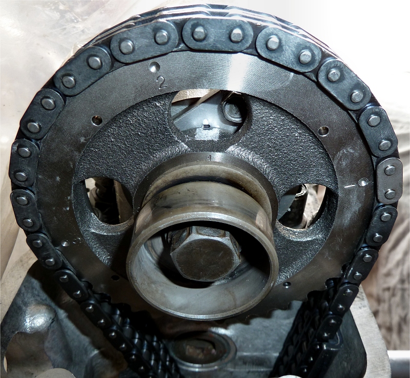
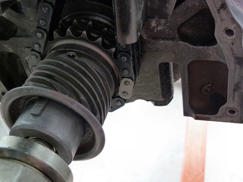
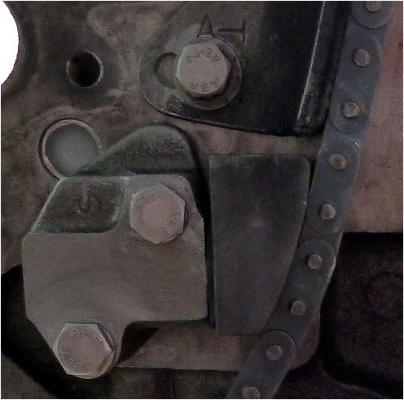
Some pics I just took of the motor I am reassembling. The full monty. The 0mm tensioner slack. Cam 1st position and bright link. Crank up, dimple and bright link.