240260280z
Free Member
-
Joined
-
Last visited
Everything posted by 240260280z
-
 You can view the page at http://www.classiczcars.com/forums/content.php?161-Rain-Gutter-Drip-Rail-Removal-and-Installation
 -
You can view the page at http://www.classiczcars.com/forums/content.php?157-Hatch-Vent-Trim-Installation
-
You can view the page at http://www.classiczcars.com/forums/content.php?158-Refreshing-Hatch-Vent-on-early-240z
-
You can view the page at http://www.classiczcars.com/forums/content.php?162-Lubricating-Refreshing-Cables
-
-
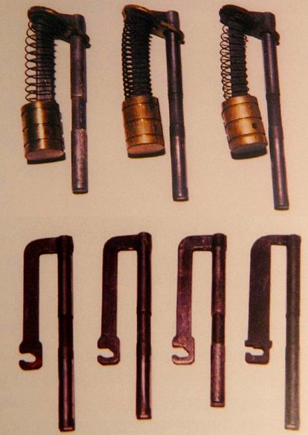
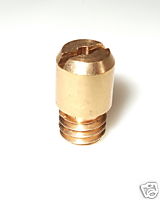
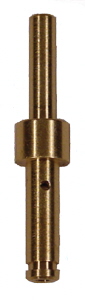
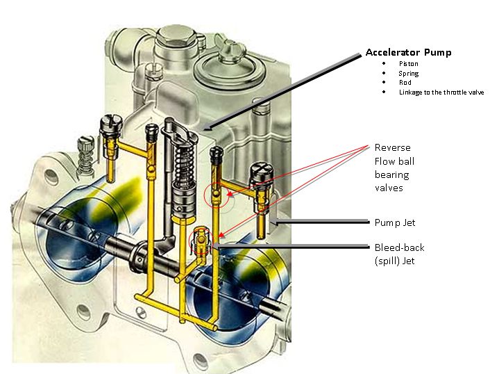
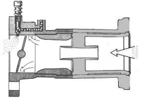
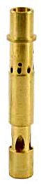
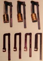
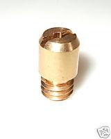
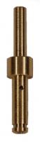
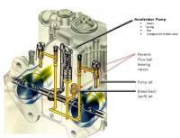
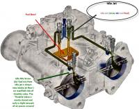
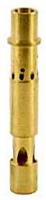
Key points to understand the functioning: 1. The Bleed-Back/Spill jet sits at the bottom of the fuel bowl. 2. When the throttle valve is closed (idle), fuel enters the bleed-back valve, flows past the ball bearing valve and fills the pump chamber as the rod is pushing the piston is up high in the pump chamber and the spring compressed. Weights atop the two other ball bearing valves keep them closed and prevents fuel from flowing out of the two jets. 3. When the throttle is opened quickly, the rod drops and the spring pushes the piston down. This forces fuel backwards. The ball bearing in the spill jet is forced upward and closes this valve preventing fuel from back flowing into the fuel bowl. The pressure also lifts the other two ball bearings and corresponding weights (opening these valves) and allows the squirt of fuel to shoot out each pump jet. 4. The diameter of the pump jet holes, the length of the piston's excursion, and the spring tension affect how much fuel is squirt and the time duration of the squirt. 5. When the throttle is opened slowly, the rod also drops but the fuel squirts slowly back into the fuel bowl as the ball bearing valve in the bleed-back/spill valve is designed to "bleed" on slow throttle transitions. In fact the progression circuit is designed to be the key supplier of fuel during slow throttle transitions...however some fuel will inevitably go through the pump jets. Size of the bleed back valves, accelerator ball bearing weights and piston spring pressure are the key factors in how "leaky" the pump jets are in slow to medium transitions and also can be customized for normal fast transition squirts. Accelerator pump rods and springs can come in different sizes. A notable Weber user on this site recommends 10mm rod throws for Datsuns. The pump jet. Note the a very very small washer/gasket accompanies this part and comes with most rebuild kits. Back-Bleed/Spill Jet that sits at the bottom of the fuel bowl
-
For bleeding the master hook a small hose to side of master and run it to the reservoir.The recycles the fluid and makes less mess.
-
Try Mothers or Meguiars products for car cleaning that are commonly available at Autozone,Pepboys,Walmart. Find one that states "for road tar"
-
Found These: Front: http://www.porterfield-brakes.com/product_info.php?productID=11222 Rear: http://www.porterfield-brakes.com/product_info.php?productID=3985
-
I read good reviews of these pads from "down under" 6 years ago and put a set on my Z. Had it on the track once and no fade but I was not pushing like you: PBR Metal Masters http://www.pbrperformance.com.au/performance.htm
-
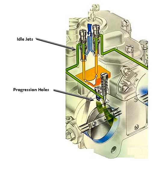
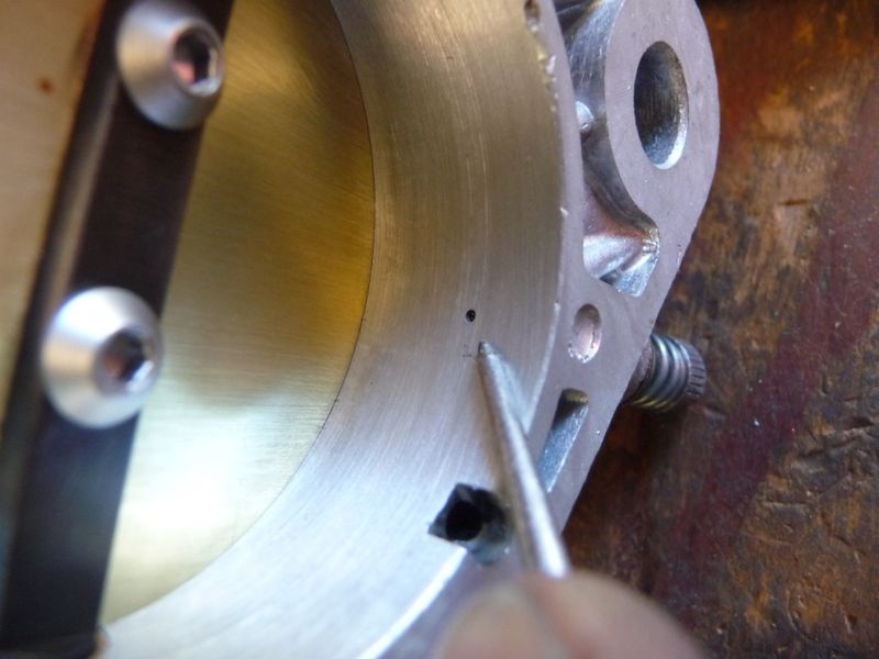
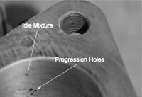
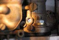
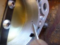
Progression holes can be viewed from above by simply removing a threaded brass cap. This inspection is important for setting the throttle valve position at idle as it should be at or behind the first progression hole. In this photo,you can see that the throttle valve is blocking the first of the three progression holes. It is a wee bit too far forward as it should only block~ 1/2 or less.

-
Very nice.
-
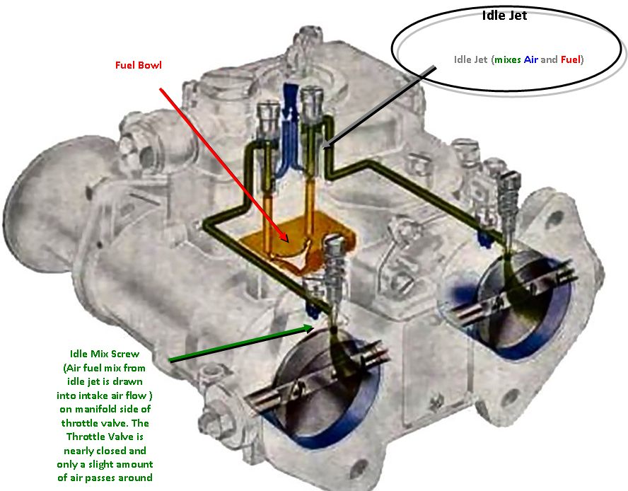
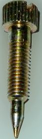
Idle Circuit Drawings Idle Mix Screw Idle Mix Hole Note that it is on manifold vacuum side of the throttle valve and is subjected to a large pressure difference that pulls the air/fuel mixture from this hole. Some air also flows by the throttle valve at idle to dilute this mixture.


-
Thanks, I am in the same boat but now I am starting to put it all together in my head so I figured that I would make a tutorial thread. I am no where near the expert level that I want to be (yet) but I am presently getting hands-on experience and delving into the theory in parallel so that I am not "parroting" too much For the rest of this thread, I'll add similar details for each circuit, add some rebuilding details, then compile some tuning info specific to Z motors.
-
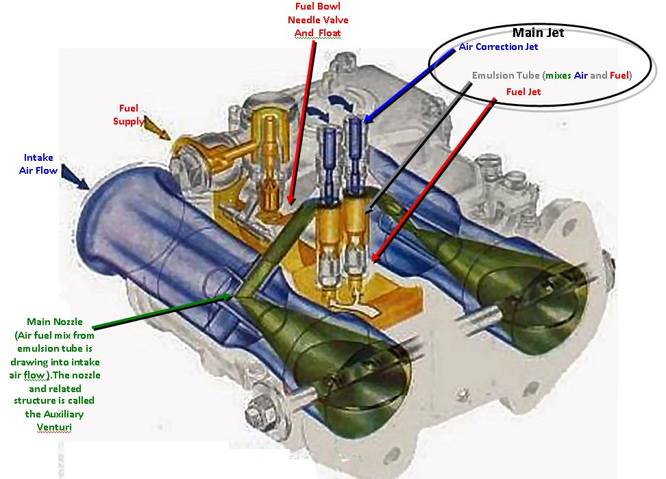
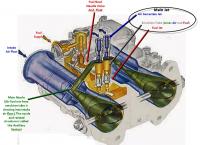
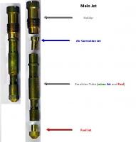
Now some drawings showing the Main Circuit and its components.
-
It came with the car. I believe it was an msa aero 2 kit w/o the side parts (here). I sold the parts and now have a gnose and open back. http://www.ridejudge.com/ride/38427/1977-nissan-datsun
-
http://www.classiczcars.com/forums/showthread.php?43162-What-is-best-way-to-add-an-electric-fuel-pump-to-early-240z&highlight=fuel+pump+oil+switch
-
Put the low pressure fuel pump near the tank so that it primes by gravity and so that it pushes the fuel. You can put a filter between the tank and pump to protect the pump and carbs. The carbs have built-in filters that should catch bits if your pump starts shedding impeller metal/coatings. A regulator near the carbs and feeding them ~3.5 to 4 psi (measured at the carb) is required. Cap off and seal the head where the mechanical pump was removed. Do not use a high pressure fuel injection pump unless you have a good fuel pressure regulator with a bypass outlet for feeding the return line. An unused power lead in the harness runs from the fuse box area to the fuel sender area. You can use a 78 280z oil pressure switch and a relay to control the pump operation safely.
-
efi overview: http://atlanticz.ca/zclub/techtips/efisystem/overview.html
-
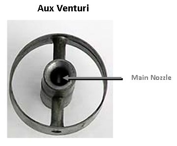
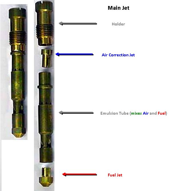
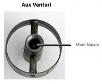
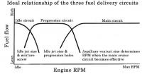
I am exploring Weber carbs and decided to try to simplify and present their functioning so that others can quickly grasp the basic concepts. To do this, I decided to make a fictional path of design that Mr.Weber, may or may not have traveled. I will provide further details for operation and maintenance in future posts, however this first post is a very simplified introduction. Blue The Ideal The simplest carburetor design that comes to mind would be a tube to flow air with a source of gasoline spraying in the middle of the tube. This would provide even distribution and symmetrical mixing at the highest velocity point of the tube. Approaching the Ideal: The Main Circuit The Weber carb commonly used on Datsuns is basically just a tube with a fuel nozzle in the mid-stream of the air path. Unfortunately another part was required.... the Throttle Valve. To control the amount of fuel and air drawn into the engine a throttle valve was added. Its location was chosen to be downstream from the fuel nozzle as the manifold vacuum on the motor side of this valve would otherwise suck the fuel from the fuel nozzle when the throttle valve was closed. The main drawback of the throttle valve location being down stream is that it still blocks the air flow when open and, fuel sprays over it and can also be deposited on it. In addition to a simple tube with a fuel nozzle design, Weber shaped the tube so that it was narrowest where the fuel was drawn into the air stream by using the Venturi principal. This promoted fuel draw and fuel distribution. It is interesting to note this simple tube and nozzle design is nearly identical to a modern high performance fuel injected individual throttle body (ITB) manifold architecture. Reality and The First Corrective Actions: Adding the Idle Circuit and the Emulsion Tube Unfortunately for Mr. Weber, the above design was only marginally optimal for middle to wide open throttle and it failed completely at idle. Here are the main problems that he faced: At lowest rpms (Idling) when the throttle valve was nearly closed, there is not enough air flow over the main nozzle to draw fuel. (Lean) At higher rpms when the throttle valve was moderately to fully opened, the air fuel mixture became too rich as too much fuel was drawn from the main nozzle. (Rich) Weber was not beaten as the fundamental design worked in principal and could be modified to work. In fact the above design is actually the so-called “main circuit” of a Weber carb. Onward: The way Weber addressed these two problems of fuel flow at both ends of the RPM spectrum was: To address idling lean, Weber knew that the main nozzle was no where near the high velocity air flow so he added a new and totally separate second so-called “circuit”: the idle circuit. Basically he added a needle valve on the high vacuum downstream side of the throttle valve. This needle valve independently controls the amount of pre-mixed fuel and air (mixed upstream and not shown for simplicity) to flow past the throttle valve and feed the engine when the throttle valve is nearly closed (and the main circuit was not functioning due to low air flow). The simple one circuit carburetor now becomes a two circuit (Main and Idle) To address the need to lean the mixture in the main circuit as the throttle valve approached "Wide Open Throttle valve" (WOT), he added a “fuel/air mixing tower” with holes in it called an “emulsion tube”. Air and Fuel mixing took place in and around this tower before the fuel was drawn out of the main nozzle. Fuel entered the tower at the bottom of a well and air entered from the top. As the fuel demand increased approaching WOT, the fuel level in the tower& well lowered and in turn exposed more air holes thus mixing more air with the fuel. This ultimately leaned the mixture (as required) in the main circuit as more airflow through the carb occurred. Emulsion Tube Weber now had a 2 circuit carb design: One being the idle circuit and the second being the main circuit…. But how to switch from one to the other slowly and quickly? Dealing with the Transitions: Adding the Progression Circuit and the Acceleration Circuit. The Progression Circuit (for slow transitions from Idle to Main): Weber found that, as the throttle valve slowly opened, when transitioning from the idle circuit to the main circuit, the air flow required to activate the main circuit did not occur quick enough. This delay in the main circuit starting caused a lean spot between idle and main. The solution used by Weber was to simply add more fuel holes near the throttle valve. These holes were drilled upstream of the idle needle valve port. As the throttle valve opened, it exposed each successive hole to the manifold vacuum. In turn, (due to high velocity air and manifold vacuum) it would draw more mixed air/fuel from each progression hole. For economy, the source for air fuel Weber used was the idle circuit. The Accelerator Pump Circuit (for fast transitions from Idle to Main): Weber found that if the throttle valve opened quickly (when transitioning from the idle circuit to the main circuit) the progression circuit above did not have enough time to operate as the airflow suddenly was across the whole carb throat rather than up near the roof and progression holes. This sudden bust of air and delay in the main circuit starting caused a lean spot between idle and main. The solution used by Weber was to add more fuel by using a one-shot-squirt-gun-like pump that was activated on a quick throttle opening (hammering the gas pedal). The design also had a clever feature where slow throttle valve openings did not squirt additional fuel (to be shown in more detail in subsequent posts). Summary: - A Weber side draft carb used on many Datsuns has two independent "circuits": The Idle Circuit and Main Circuit). - A so-called Progression circuit is used to aid in slow rpm transitions from Idle Circuit to Main Circuit. - A so-called Acceleration circuit is used to aid in fast rpm transitions from Idle Circuit to Main Circuit.


-
Also a moral application of "Give Caesar what is Caesar's" falls into this situation.
-
Today: Drove by a cellphone in the middle of a T-Junction in our subdivison. Stopped, on the way back to have a closer look. It was not in bad shape and has been run over but just scratches on the outside of the clam shell. Put the run-over battery (that was on the road 3' away) in the phone, made a few calls to the last dialed numbers with no answer...and later when the owner called back, hand delivered to a neighbour ~ 400m away... even went back and found the battery cover. The guy's wife had entered the house, looked on their home phone and asked why her husband had dialed the house 3 times from his cell when she knew he was working in the garage. FYI:It was a Samsung
-
I saw that on craigslist or ebay last week... beauty. Congrats!
-
Yeah it seems like if you wait for a year to cycle, and watch the weely sales flyer, you can get most important tools at canadian tire for 45% to 65% off (ratchet sets, wrench sets, screwdriver sets, bit sets, power tools, torque wrenches, etc. but only princess auto has the roll-up-the-rim tool
-
Interesting. We have a few z's for sale here in Halifax, Nova Scotia, Canada....very close to Europe by sea (in fact there is a large autoport here). If any Europeans want nice z's pm me or my buddy Ross. Some examples of cars we have now: http://zsportcanada.com/listings/view/Datsun/240Z/81/ http://zsportcanada.com/listings/view/Datsun/280Z/77/ http://zsportcanada.com/listings/view/Datsun/280z/70/ Here is a Z we sold at the Autoport: