Jeff Berk
 Subscriber
-
Joined
-
Last visited
Everything posted by Jeff Berk
-
 I had to change both the dash and fuse box harnesses but the problem ended up being due to a bad connection.
 -
It worked out fine except for an extra wire. But then again, my original wiring had undergone so many modifications, I might of been missing that wire due to PO's re-wiring to install a radio or anti-thief system.
-
I have a 260z that has undergone may upgrades, downgrades and lateral grades. The carbs right now are 4-bolt round tops. Somewhere along the modifications, the return flow fuel line was disconnected and plugged. I'm getting vapor lock issues on hot days when I'm driving hard so I'd like to reconnect this line but I'm not sure where it goes. It is likely in Section EF (Fuel System) of the FSM; however, the only copy on line is a bit too fuzzy to read or to follow the diagrams. Could someone please pm me a copy of this section in a better resolution? Thanks Jeff
-
I think you might want to get a tie-rod fork (a.k.a. pickle fork) from Autozone, Advance Auto, or whoever to separate it. They loan out these tools and you need just to return them within 30 days for a full refund of the deposit. https://www.homedepot.com/p/Powerbuilt-Tie-Rod-Ball-Joint-Separator-648468/204505272?cm_mmc=Shopping|THD|G|0|G-BASE-PLA-D25T-HandTools|&gclid=Cj0KCQiA_5_QBRC9ARIsADVww153tZZuaYVzwUjeTD87h7OVzBB9gakynvGAtcEwbrHDdULQWLN0hYsaAlwgEALw_wcB&gclsrc=aw.ds&dclid=CIGI0PLzudcCFQK7Twodco0HGg
-
Does anyone have a fast idle setting screw tab off of a 240z or 260z. I'm talking about that triangular piece that is attached by two screws and uses a third screw to push against the throttle linkage to increase the RPM for tuning the carb's? I've got a 260z with round tops so the setup is likely the same as a 240z.
-
I'll give that a try after I wash off the underside. Thanks
-
I've got an oil leak in my 260z (L28 engine). Not having a lift, I asked a mechanic at NTB to see if they could find the source using their lift. I suspected either a rear seal (I replaced it a few months ago) or the oil pan gasket. Instead I was told that the upper oil pan was leaking. What is an UPPER oil pan? From what little I could find on the net I know I need to remove a cross member to replace it and it uses RTV to form a gasket, but that's about it.
-
FYI, I used dry ice to shrink mine so it would fit
-
Concerning the dash padding, it sounds like this device would work for anyone in the Cleveland, Ohio area but creating the model would be difficult. They also have a scanner with a 2-meter capacity, but I understand that 3-D scanning is not especially easy. http://thinkbox.case.edu/equipment/shopbot#centerCol Between the Cleveland Public Library's Makerspace and Case Western Reserve's Sears Think Box, there are a lot of resources here to create objects for roughly the cost of the material. Are their any detailed pictures of the 280z headlight connectors out there? From the few blurry photographs I've seen it looks like female bullet connectors embedded in a socket. That can't be that hard to make. The water-proof outer shell can be created using a flexible filament (e.g. NijaFlex).
-
I guess my question is what would you do with the design files (or whatever they are called) and the items generated by the prototype machines? If you create files that can be used to control a simple 3-d printer for example, would you offer to "print" the item for the Z community for the cost of material, for a fee that included the material and a profit (assuming the college permits commercial use of their equipment), or to sell or give the control files away to the Z community for their use on their personal 3d printers? I'm not saying that this is not a good idea, there's a video out of Jay Leno using a 3-d scanner and printer to create parts for his stable of cars and there are currently very few 3d printer files out there for Z parts. I'm just wondering what is the best way of using these resources. Jeff
-
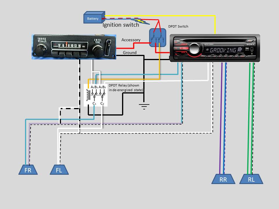
I’m trying to figure out how to hook up the original radio as well as a modern day radio in a 1974 260Z. The original speaker is gone and I have two door and two rear compartment speakers. If I chose to have the original (monaural ) radio power the two front speakers and still be able to run the two front and two rear with the modern radio, I’m assuming I need to do some special wiring since both radios cannot power a speaker at the same time and since the two front speakers cannot be hooked together for the original radio because that will be a problem for the modern radio that needs to keep them separate. Please look this over and offer suggestions on if it will work or if there is a better way. 1) Power from an ignition controlled source goes to a DPDT switch that toggles between powering the original radio and the modern radio (red line) and a power feed to a DPDT relay (orange line) or an open circuit. 2) The original radio on the left has two speaker wires, the positive wire (white) and the negative wire (white with a black dash). The negative wire splits and goes to both rear speakers. The positive wire splits and goes to contacts A1 and A2 on the relay. 3) The modern radio on the right has eight speaker wires with the rear speakers wires (green and blue pairs) going to the two rear speakers (RR and RL). The front speakers have two pairs of wires with the two negative wires doing to the two rear speakers (turquoise and white with black dash) and the two positive wires (turquoise and white) going to the B1 and B2 connectors on the relay, respectively. 4) Assuming A1 and A2 are open in the de-energized state, the speaker signals will travel from the modern radio through the turquoise to B1, then to C1 and then to the front right (FR) speaker and through the white wire to B2, then to C2 and on to the front left (FL) speaker. 5) Assuming the relay has been energized by the DPDT switch which is sending power now to the original radio, A1 is connected to C1 and A2 is connected to C2 in the relay. This will send the speaker signal from the original radio to a split connected to A1 and A2 so that both front speakers are powered. The above assumes that it is OK to have the negative wires from the front speakers connected to both the original and modern radios at the same time and for the negative front speaker wires to be interconnected. I might be able to find a relay that has 4 internal switches, but that might be hard to find.
-
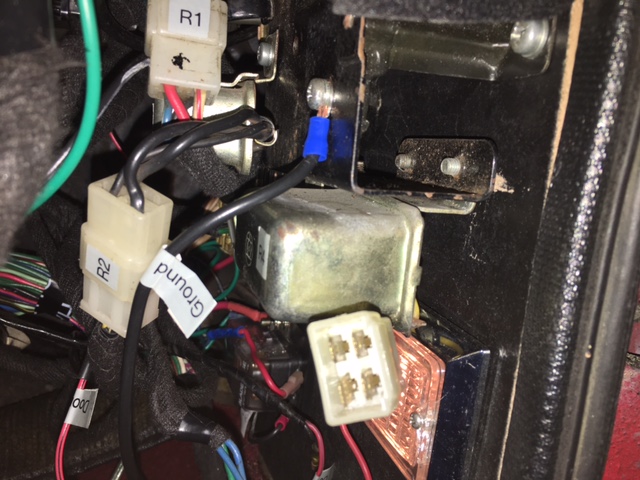
Actually, your's looks not that bad. I'm glad you have some of the wires labeled (#4 in the second shot). You might want to tape wrap some of the wires together that are going to the same component groups. Also I see some relays dangling. I 3D printed a relay holder for my two flasher relays to keep them out of the way (public library has several 3D printers). There are a number of metal bend tabs that are used to hold wire harnesses in place. See if there are any that you could utilize that could help organize the wires. If nothing else, no one will be able to see the wires once the dash is put back together. Remember that this car pre-dates cars with circuit boards and ribbon cable so there will be a lot more wires strung behind the dash.
-
OK!!!!!! I think I'm there...THANK YOU CO I went to Autozone and picked up a new relay and wired it in, adding a ground wire since the new relay had a plastic shell. So far it seems to be working. Now to secure the wires so it doesn't look jerry rigged. Now onto the next electrical glitch.
-
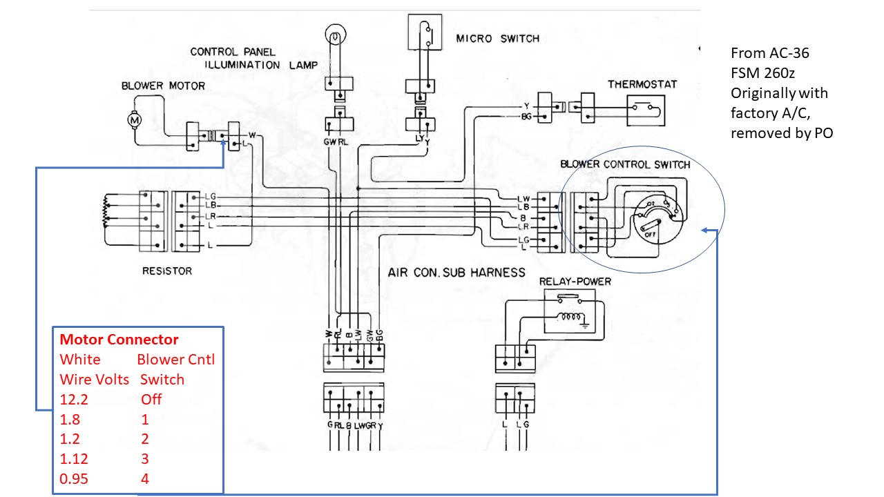
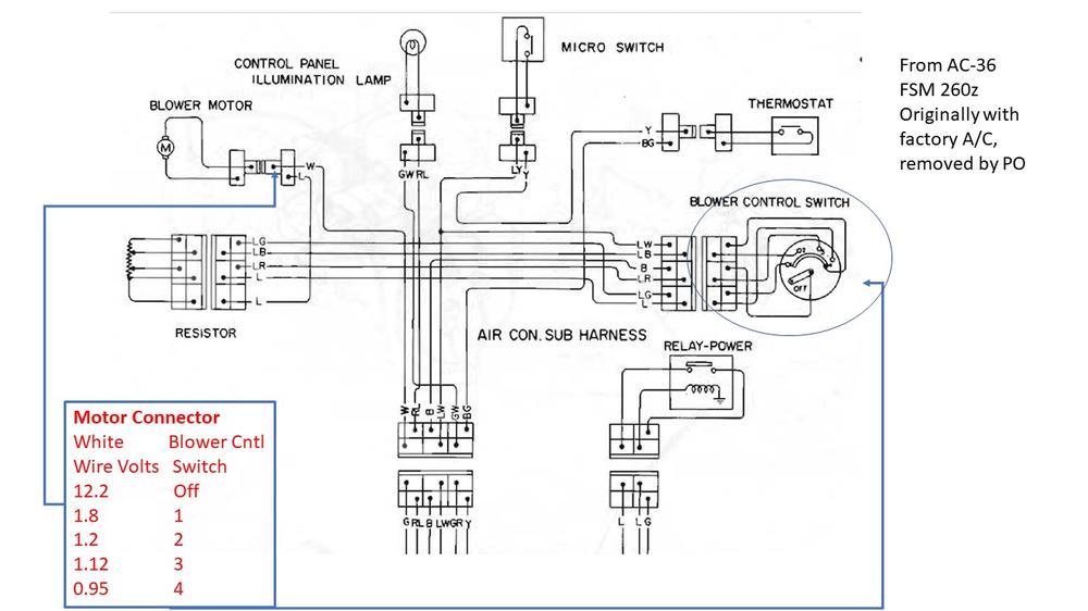
CO: I removed the relay cover and one of the points looks rounded. I lightly sanded them with fine sand paper (wish i still had my points file). With the ignition OFF/fan OFF/Relay installed: There is 12 volts between the diagonal G & L wires while back probing. Therefore there must be continuity. With the ignition at ACC/fan OFF there is no click, points are open, between G&L 0 Volts, 37 ohms. With the ignition at ACC/fan ON there is no click, points are open, between G&L 10.2 Volts. A relay is inexpensive enough, maybe I should buy one. As a side note, I found that plugging/unplugging the relay blew a fuse but not the one for the blower motor. For the dash lights (not working right now) and the voltage regulator under the hood. Jeff
-
I had sprayed the contacts with cleaner but have not used anything abrasive on the female blade connectors. I'm going to try and clean the relay internal contacts.
-
CO.. I had to go back to the car and check but yes, with the G&L jumpered, the fan does obey the speed control and I get the 4 speeds and off. I do hear the relay click when the ignition is turned on with the relay connected. With the relay disconnected again, I'm seeing 12V on the non-diagonal L wire. Interesting that I'm seeing 0.1V with the ignition off. The relay appears to be grounded to its shell; however, there is a fourth wire on its connector (seen in the photo as a head-on view) that has no matching wire on the mating harness connector. This could be a ground that Nissan chose not to implement. The fan relay is just to the right of the "Ground" tagged wire. The ground wire was added because I was worried that there were too many ground wires from different components connected to a single grounding wire in the harness and was a potential cause of some wire melting events I experienced. To the right and up a bit are two screws that mount the power relay to the relay panel. That is how the relay shell is grounded. As you can see, I went a little crazy with the label maker. JB
-
Well... when I jumper the L & G wires the fan runs at full speed even with the ignition off. Questions: 1) I'm assuming that means I have a bad relay. 2) Can I rejuvenate a relay by opening it up and cleaning the contacts? 3) Can I use a modern relay or do I need to hunt down another used one and keep my fingers crossed?
-
Thanks CO, that's a start. Diagram BE-53 shows fuse 5 counting down on the left side powers the blower. I'll clean it up as well as the fuse-box clips. I'll also try what you suggested for the relay. I had replaced it with a used relay because the original one had a fried wire. Thank you for the help on this. I'd like to get this working so I can drive this car into late fall.
-
I've been at this for some time so I need some idea what to try next. Background: This is a '74 260z that formerly had an A/C. The original controls are still there but the vacuum tubes are disconnected. The fan was not working. 1) I removed the fan and when I applied power to the blower motor connector, it ran at full speed. 2) I checked the blower control switch using a continuity meter and each position seems to work. 3) The power relay puts out 12 volt with the ignition in the on-position. 4) I verified the proper electrical connections using the color codes on the attached figure and there are a lot of them. 5) I traced (using a continuity tester) the Green wire from the power relay to the heater connector where it became a white wire to the blower motor connector. The voltage at the white wire on the blower motor connector ranged from 12 volts (fan of) to less than 1 volt at the 4 setting. I'm a little confused as to how this is supposed to work and why the fan should be off (which it is) at 12 volts when if I remove the fan and apply 12 volts directly to the blower motor connector the fan runs. Can anyone tell me what to try or test next? Thanks for your time... Jeff
-
-
The one you have sounds like the one I have right now. I purchased this one: https://www.summitracing.com/parts/sum-890115 They also sold me a radiator hose adapter to install along with it but I don't want to go that route if there is a way of connecting the thermal sensor directly, especially at $50. https://www.summitracing.com/parts/atm-2283 The plug on the thermostat housing looks more accessible so I'll unscrew it and take it to a hardware store and maybe I'll bet lucky.
-
On making the old system work again, the old system looks kind of beat up (missing control knob, no enclosure box) and has some odd wiring (one wire going to the coil). I can try and open it up and look for a relay to replace, but I'm not sure if that's the issue. Summit Racing had a screw-in sensor that looks like the one 7tooZ posted but it has a 3/8-inch pipe thread. What type of threading is used on a Z? I noticed that 7toZ has a bushing on it. Is that a NPT to some type of metric bushing? If so, where do you find such an animal?
-
-
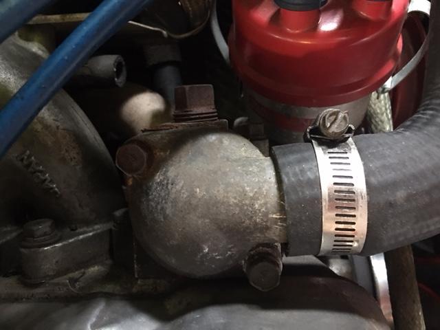
I am trying to figure out the best way of controlling the electric radiator fans in my 260 Z. The previous owner installed dual electric fans operated by a thermostat with a temperature probe in the upper radiator hose connection to the radiator. The temperature switch no longer turns off the fan so that even when the car is cold the fan is running and I need to pull the fuse. Would it be best just to replace this with an identical unit or should I install a temperature sensor in place of the threaded plug of the thermostat housing? If so, does anyone have an idea what the threading is on this plowed? Thanks for reading this… Jeff
-
I purchased this harness thinking my old harness was bad. I was wrong so I'm keeping my old and selling this one. I've cleaned all the contacts and re wrapped it with cloth tape. I added an extra ground wire because I've had problems in the past with the original ground configuration. One connector housing is slightly damaged but still works fine. Most of the terminals have been labeled. This is reportedly off of a '74 with a manual transmission. I tested it out in my car and it seems to work fine. I'm asking $95 including shipping from Cleveland, Ohio. You can take $8 off for local pickup.