


Dave WM
Free Member
-
Joined
-
Last visited
Everything posted by Dave WM
-
-
-
-
IMHO, wait for a good reason.
-
Personally removing a working part just for the sake of making it pretty is not a good idea, yes you can break something in the process. Now if its got a leaky manifold gasket, you have a reason. Or if you have a show car and want it to look perfect that's a reason. on my 280z the 1st and last stud on the manifold common bolts were both broken. the gasket had not yet started to leak but it would have with time. So are you asking for trouble, depends it may come right off no problem and it may not. No way to know for sure until you try. IF you try it may be a good idea to have some way of heating up bolt/nuts if they seem overly tight. Some PB blaster on the nuts would be a good idea as well. I still think its not a wise move to remove it for appearance sake alone.
-
I don't see any sharp ridges from those gouges, I suspect nothing to be gained by filing, suggest you just use as is.
-
agree that seal is too far gone. FYI the FSM calls for the use of sealant, so after installing the new seal you may still need to use the goo. I suspect the OE seal is better but not sure I would pop for the extra 6x price.
-
flat file, knock off any ridges, sanding tends to be too imprecise (unless you have a very flat hard backing plate), a flat file with I believe its called a "mill cut" is what I would use. its flat and has a diamond shape pattern. Just draw it across the obvious damaged area to clean up any ridges. You will not be able to get rid of the defect but you can make it less likely to get hung up. more control than sand paper. the key here would be to not reduce the height of the pad, I think that is the main wear area that is of concern. Very little material would be removed.
-
did you try those international vendors? I was told the same thing when looking for a transmission part, they had it in japan, took a couple of weeks but got it for less than would have been if I bought from a dealer. That being said, I really don't think you will need new inserts, the damage is confined to an area that should not effect the operation once cleaned up. I suspect the dealers do NOT bother with trying to locate parts that are not in local warehouses.
-
you may try this 1st worked for me
-
one other thing, you could just dress it up with a file and see how well it operates. That is not the normal kind of wear that would be expected so it may have no impact on the function.
-
if they don't have it try those international sites.
-
maybe these guys https://www.nissanpartsdeal.com/parts/nissan-insert-shift~32608-e9800.html I have used these guys too https://www.amayama.com/en/part/nissan/32608e9800 and here too https://partsouq.com/en/search/search?q=32608E9800 just google the PN lots of stuff came up. I have used those direct from japan Amayama has great prices on things like Nissan OE bearings etc...
-
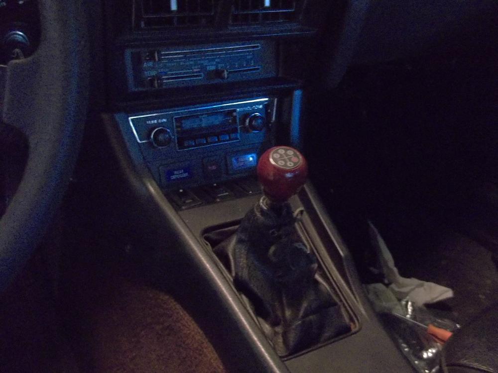
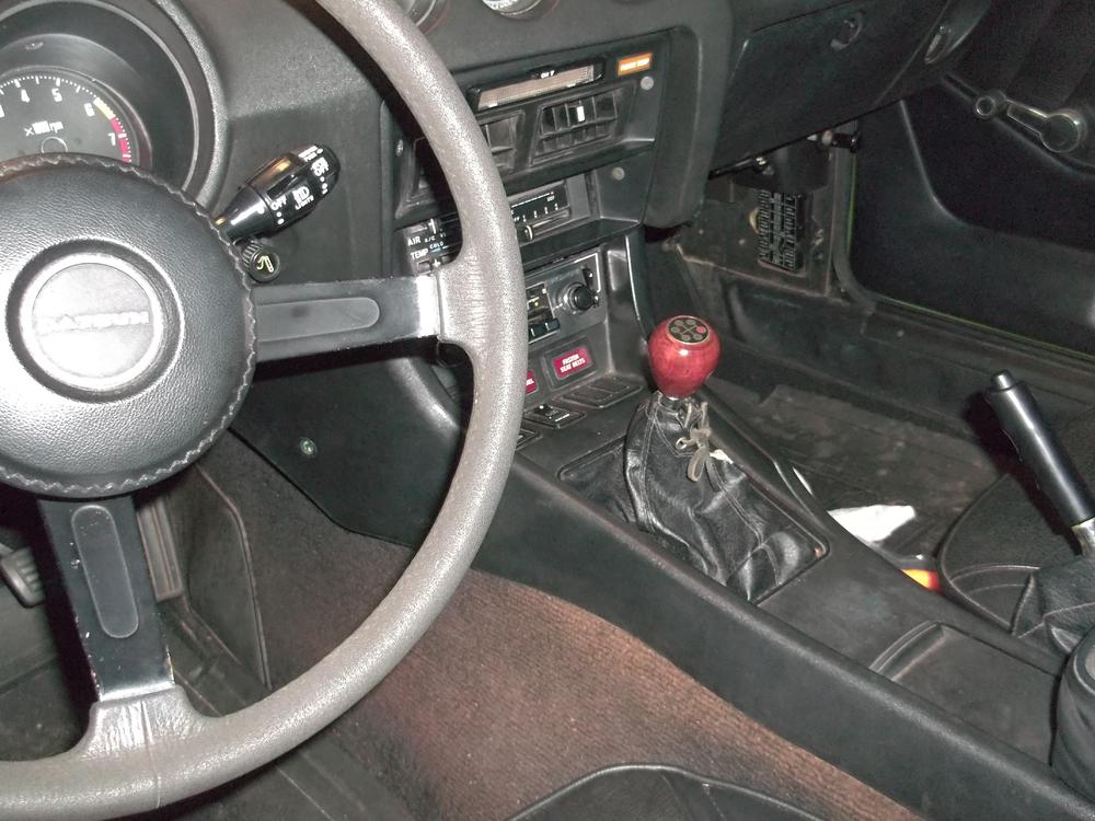
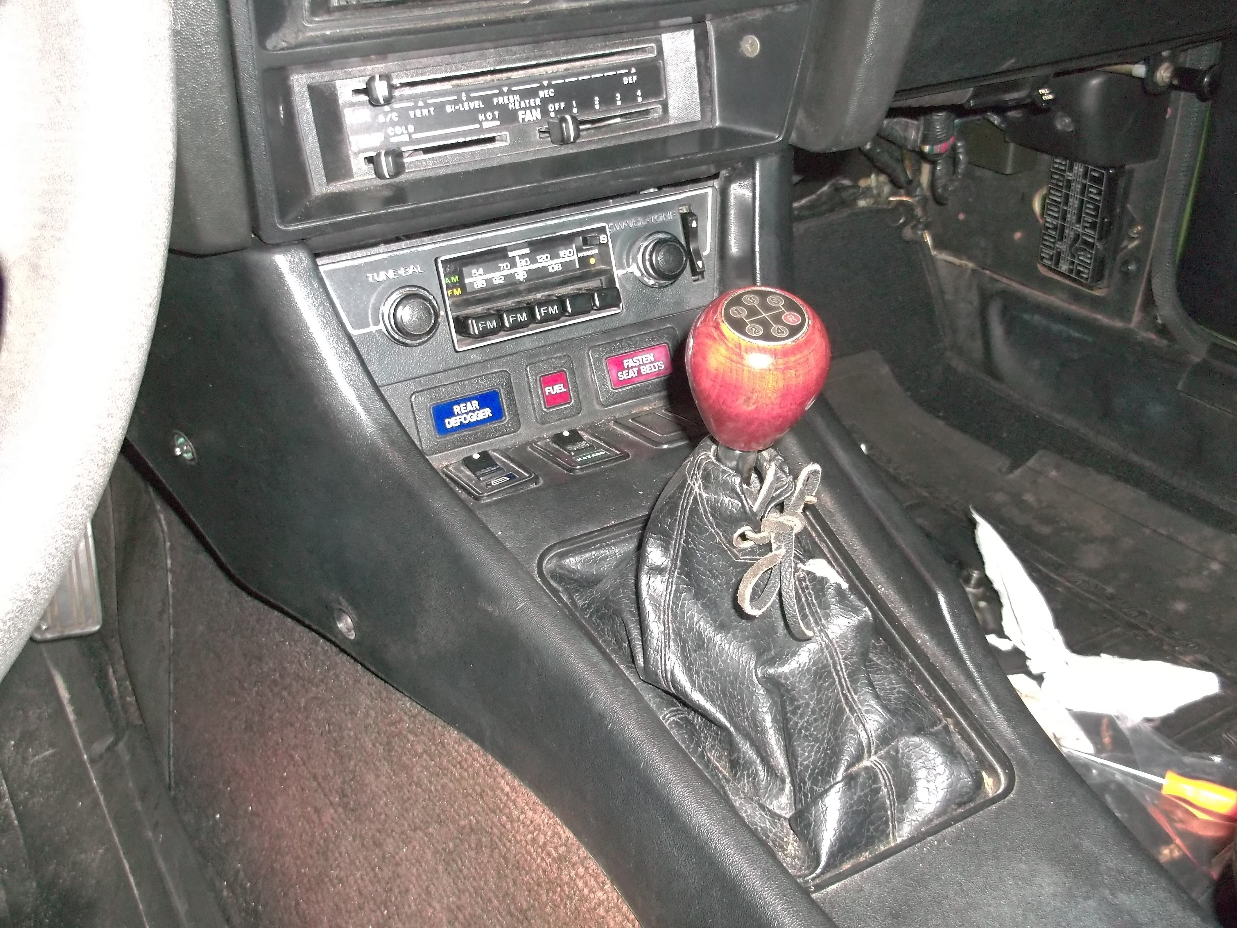
makes the radio knobs a bit easier to get at with the low position.
-
at least you had the good sense to use heat to break the bond and not break the bolt. I can only see one alignment dowel, hope the other is not MIA.
-
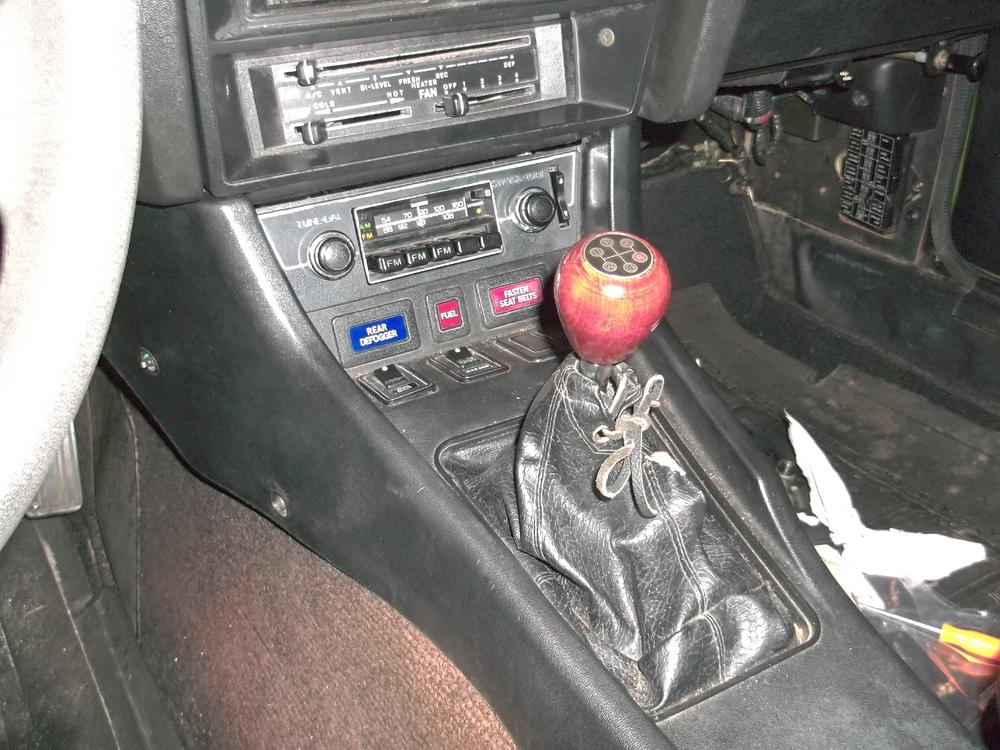
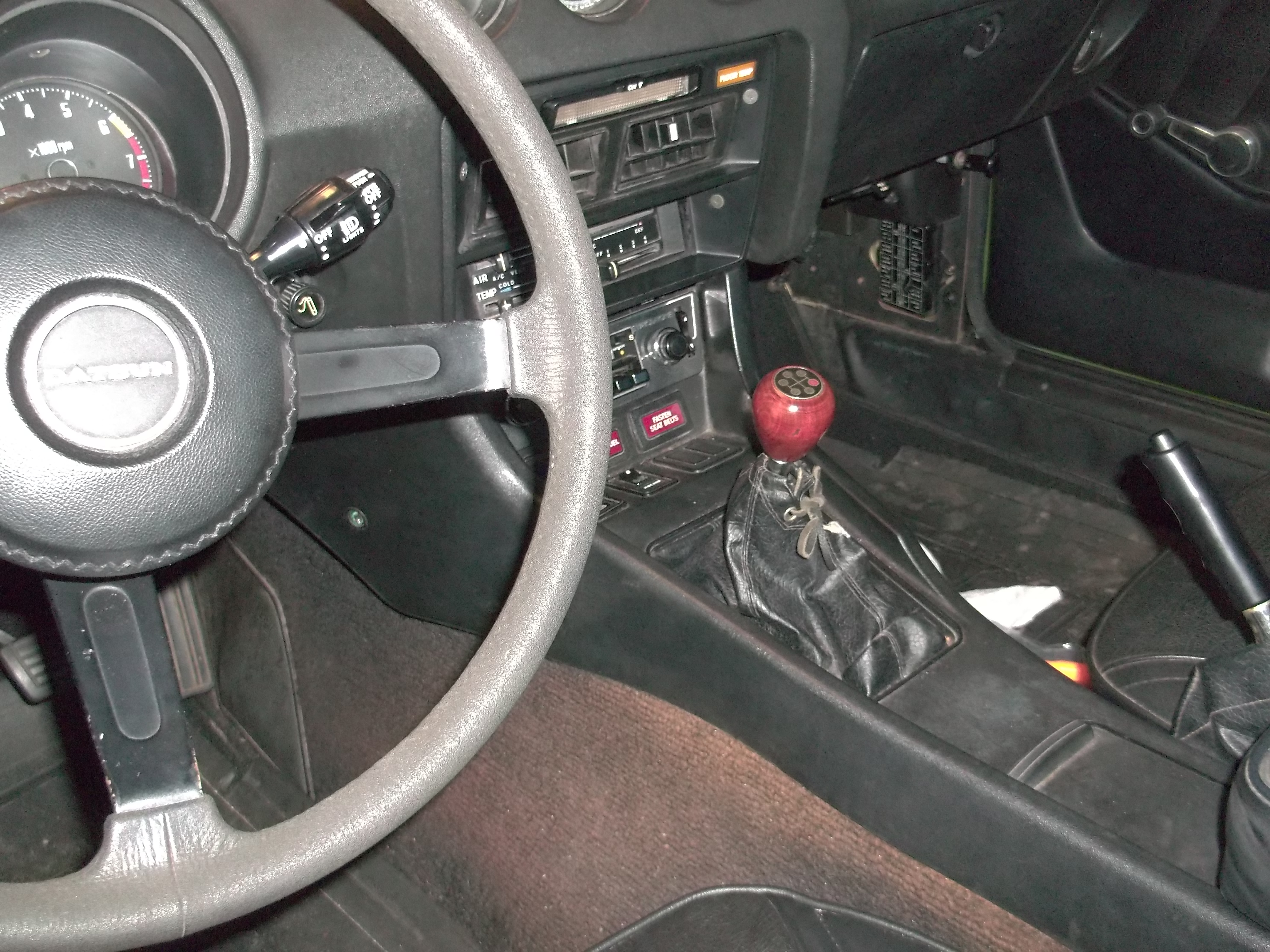
pic of it installed, actually I think 1/2" would be needed for the boot to not be stressed, 1" would be ideal for placement. I would bend from the bottom bend, I think maybe just a touch on the top. Another idea is to simply extend it by cutting in half about 2" down from the knob, thread both of the sides and use coupling piece about 2" long to rejoin. I think that would be the ideal fix. plenty of extra to allow best fit and keep it a more stock look, while still using the correct ZX end piece for the actual shifting. Use some red locktite and a jam nut on one side to perfect the thread alignment of the knob (it worked out perfect, nice and tight knob with excellent placement of shift pattern).
-
bring it over tomorrow!
-
video
-
Ebay 1000 watt 120v IIRC about 375$, seems like a lot for what it is, but it does work, and the flameless heat comes in handy. I was a Birthday present, I could never pull the trigger on it for myself, but glad I have it now. I really wanted one after breaking a Tstat housing bolt/exh manifold bolt/fuel rail mount bolt. Too bad I had to break all those before I had it. I installed it and did a test run, a little short for my taste, but still fine and shifts well, maybe better, hard to say. I will need to re bend about 3/4" more back bend as it pulls the leather boot pretty tightly now when in the forward position. 3/4 should be perfect. My leather boot is pretty worn and has a small tear in it so I will prob fix it when I get a new one and have to pull the console again.
-
I wanted to compare the feel of the two shifters, the ZX with its float fulcrum vs a Z with a fixed fulcrum. the problem with just using a ZX seems to be the shape, its more of a straight line vs the "S" pend of the Z. I presume this would have put the shift knob at an awkward angle, so I decided to try bending it. I used a "bolt buster" which is a hand held induction heater the heat the shift shaft where I wanted the bends to take place. 1st need to remove all the plastic of course, this was the pad that fits on the ball end of the shifter, and the plastic spring load fulcrum. After that I chucked it in the vice and selected a heating coil that was a little bigger than the metal shaft. I did the bottom bend 1st, maybe took a min for the metal to get hot enough to become plastic, then applying pressure in the desired direction completed the bend. After it cooled did the same with the top bend, but since it was close to the top I used a tool to get more leverage. In this case it was just an offset box wrench, larger enough to fit over the end of the shaft, just past the threaded part.
.thumb.JPG.8613f1a0934a5d7024e5b8ce801d4ce8.JPG)
.thumb.JPG.83177e91e61d3e03ed9f35917b31473d.JPG)
-
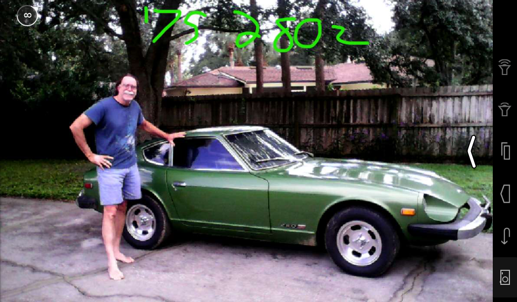
1st is taller so you can stay in it longer, and shift in 2nd later. Its not really much of a big deal. the real benefit is just having that very tall 5th for low rpm high speed stuff. One other thing I notice is the 4speed shifter seems tighter. It is different enough to notice but not so much that I would say a problem. It may have to do the kind of shift lever (not using the ZX but rather a notched for clearance non spring loaded shifter). I do have a ZX style shifter that I plan to bend and lengthen, but I don't know if that will feel any different. As far as tunnel cutting on an early 240, I have no idea, it fits my 75 without cutting. Tip you do NOT need to remove the center console to install the shifter, just have someone help you by pushing down the shifter into place while you help guide the shifter into the transmission after its bolted up to the engine. there is not a lot of room but it can be done. Then install the pin and C clip and pull the rubber boot over the transmission shifter ears. The key is to have the shifter already in the car (push it up from the bottom to clear the large rubber gasket and leather boot) pushed up and out of the way while engaging the trans to the engine. This will save you the hassle of having to remove the center console (don't crack it) and all the associated wires for the lights and radio.
-
do I see an intake snorkel ? the one that fits on the intake side of the air filter and ducts in air from under the passenger side fender. (not the elbo that goes back to the AFM).
-
its the rebuilt one that is in there now.
-
will take a look. I am thinking a bearing puller may work, the kind with the knife edge bevel.
-
the final setup was the orig reverse gears (chewed up a bit) and the replacement 3rd gear you sent (gear/baulk ring/needle bearing). It still had a little bit of the noise to which I think was perhaps a slight defect in the output shaft. I the reasoning is since the 3rd gear resides on the very end of the shaft (4th floats on a needle bearing that rides on the main) any run out will be the greatest on that gear (3rd) this gets transmitted via the shift fork into the shift rod, and then into the front of the bell housing. I am not sure why the replacement you sent seemed less noisy if that is the case, but I just wanted to try it and see. If the trans was still noisy installed in the car the next operation would have been a complete tear down and check for run out of the main shaft. There really is nothing else to go wrong, the box is so simple. I know the next time I work on one of these the very 1st thing I am doing is checking for runout.

.JPG.8c2e25d0dc642bda5facbac1500ffc28.JPG)
.JPG.83e982a109911070bd6040585cd0e6aa.JPG)