inline6
 Subscriber
-
Joined
-
Last visited
Everything posted by inline6
-
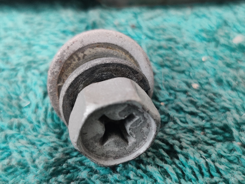
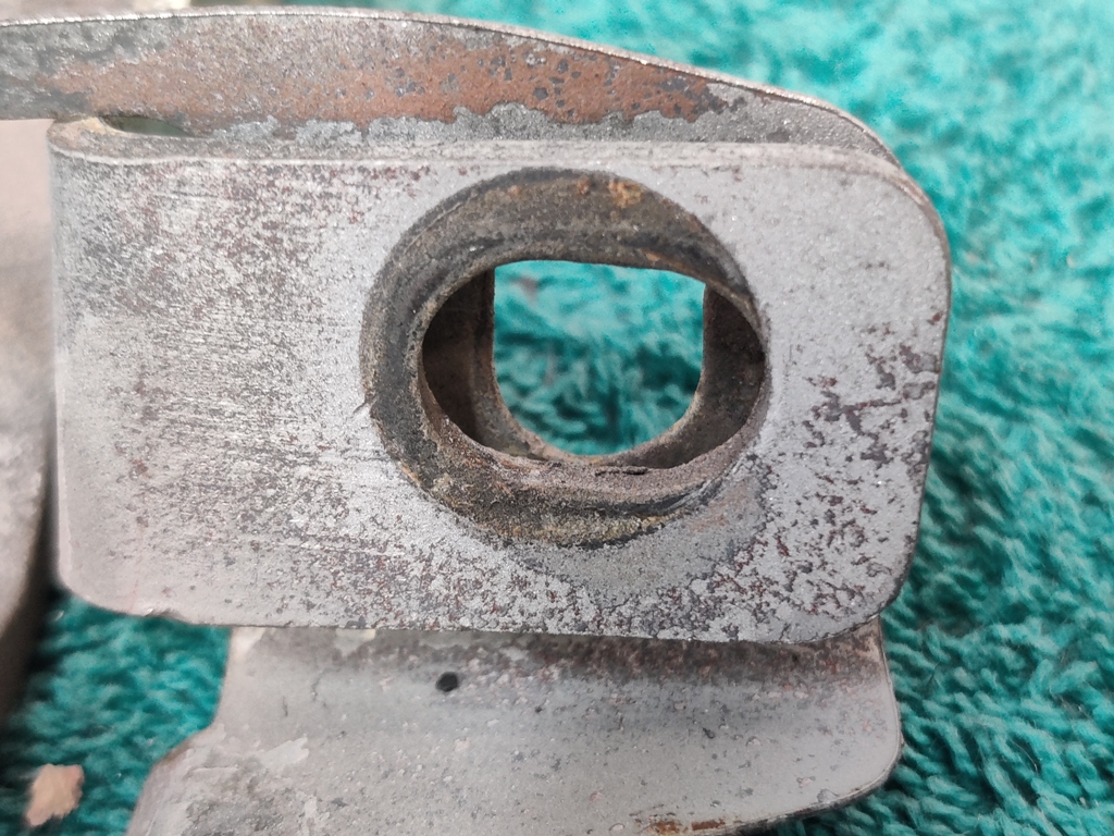
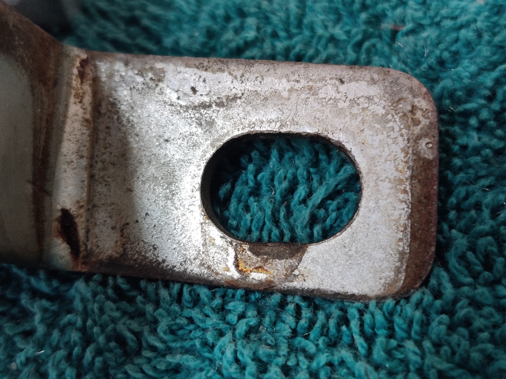
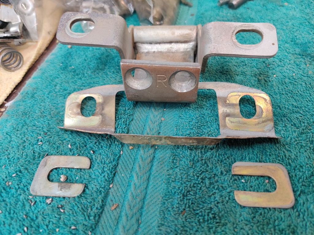
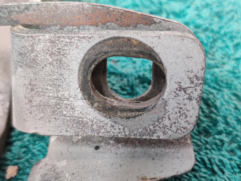
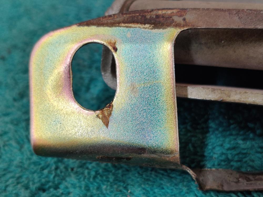
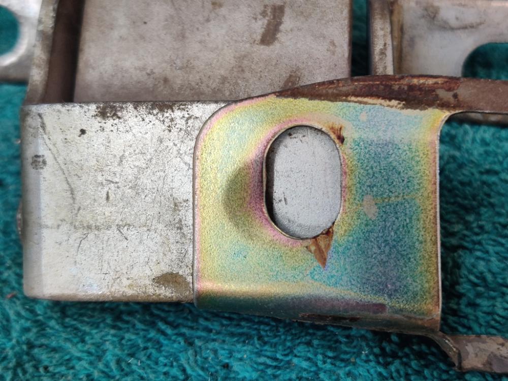
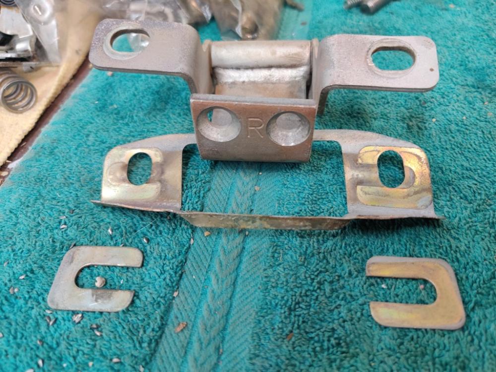
 I have purchased from that site (him) several times. My most recent order was in December. No delays in communication whatsoever. I bought a coil, two Hella H4 bulbs, no longer available nos oem door strikers some grease caps and some NGK plugs. B2433-U3110 coil $60 (ended up buying a blem unit for less) 80570-21000 rh door latch striker on body $16 80571-21000 lh door latch striker on body $16 99996-70476 Hella h4 kit $60 40234-S0400 set of 2 front wheel bear dust grease cap $14.30 (6) of NGK BP6ES $2 each Garrett
 -
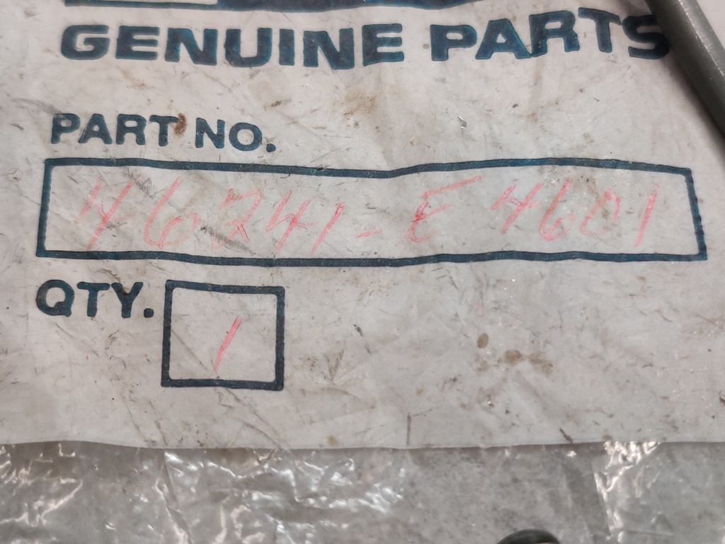
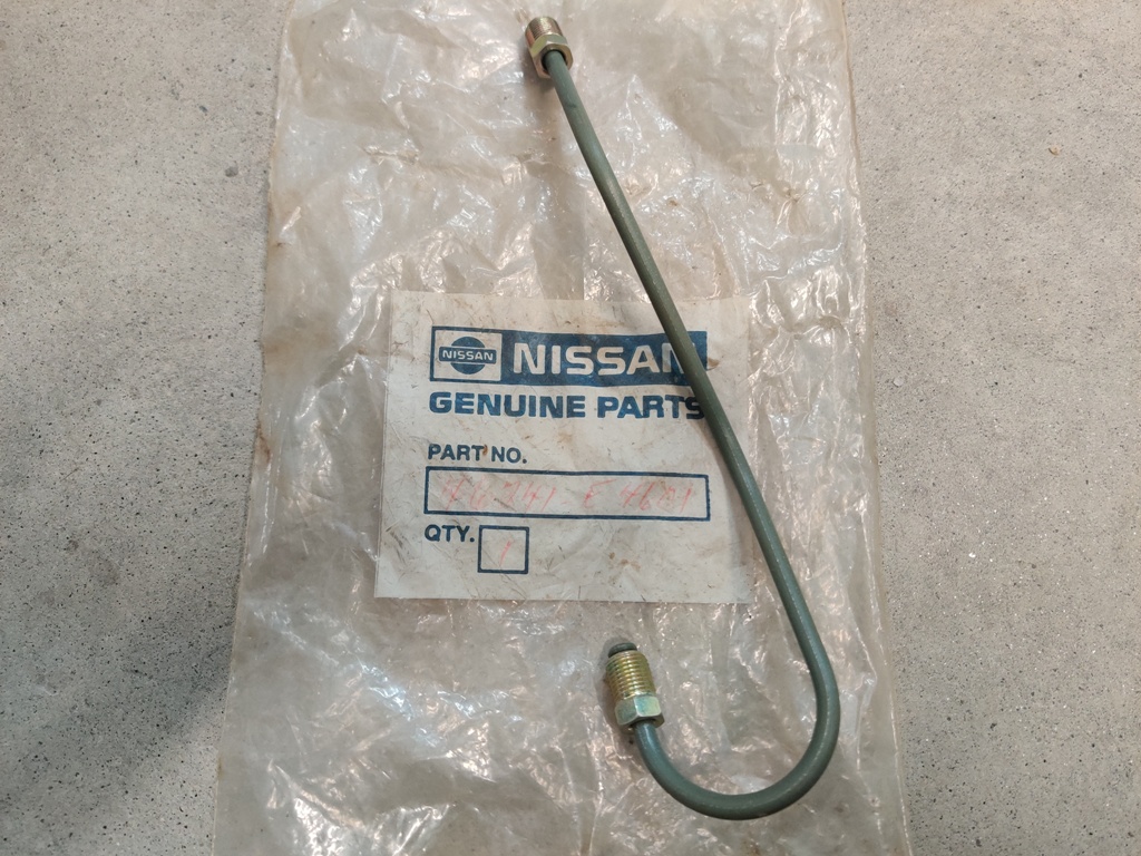
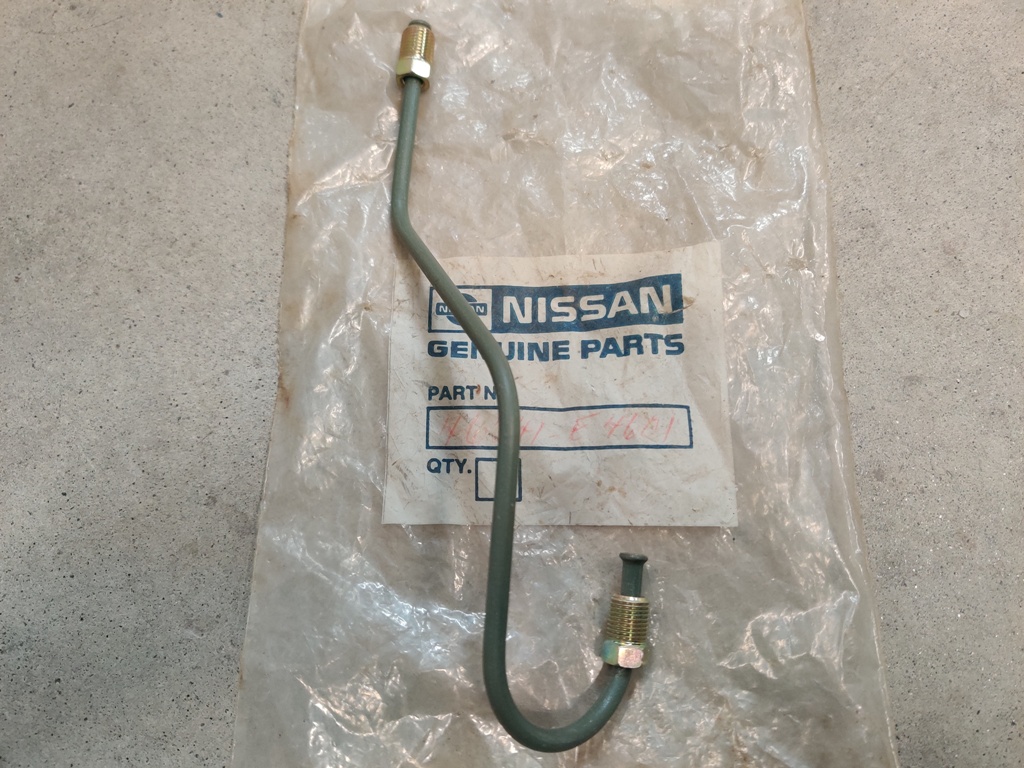
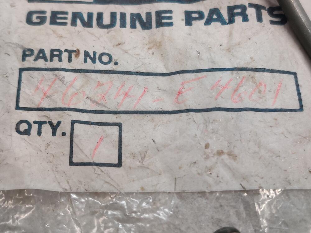
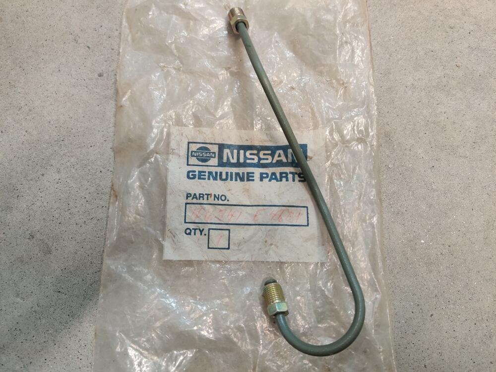
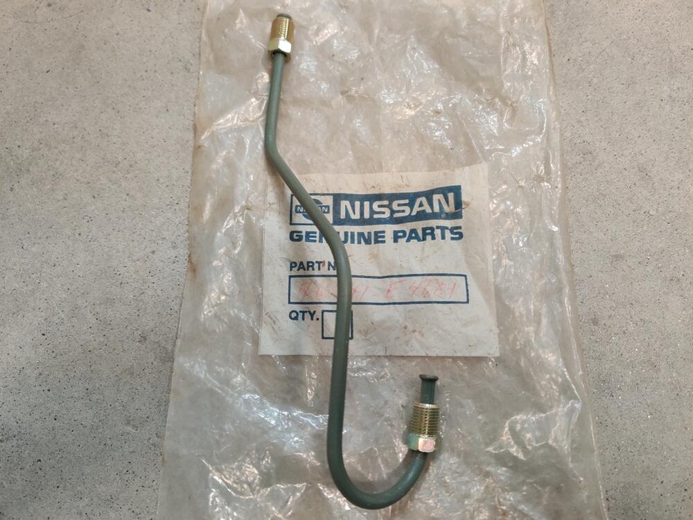
Oh! Well, that is a bummer because I may not have one of the hard lines I need then. 46221-E4601 for the front, is the one I may not have (#1 here in the "microfiche"). I happen to have a new old stock #2 though. I don't have any pics of these lines on the car I am restoring. I'll need to grab them and new style MC and a compensator to see what's what. Whoever fitted the new style cylinder may have bent the existing lines to fit rather than swapping them. If so, perhaps I can bend the front line back to original shape.
-
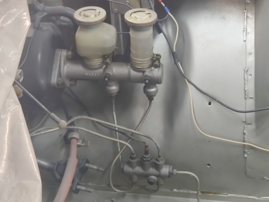
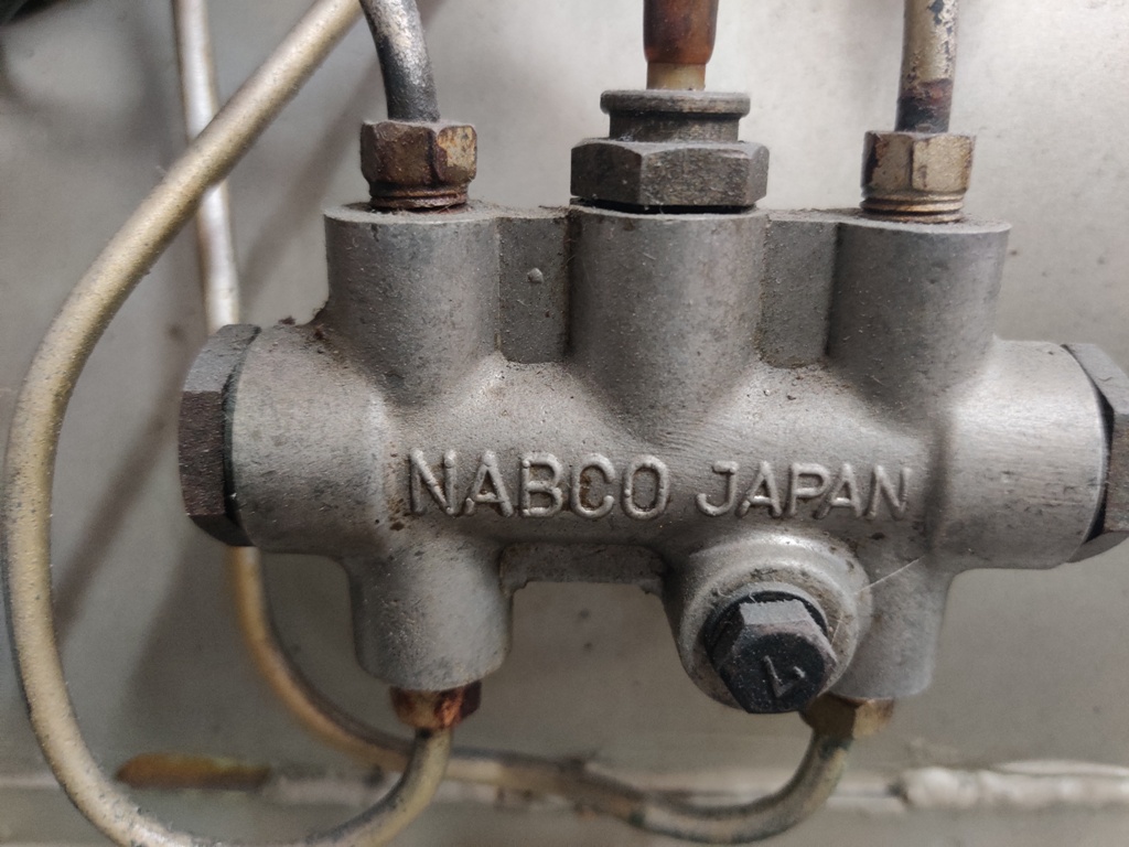
Yes, that is very helpful. So, for the later style, you "swap the lines". Because they are hard lines, I am guessing "swap the lines" isn't literal? You leave the hard lines in place at the compensator and bend them so they "swap locations" at the master cylinder? These are pictures from my 240z "track" car. It is a series 1 with a later style master cylinder on it.

-
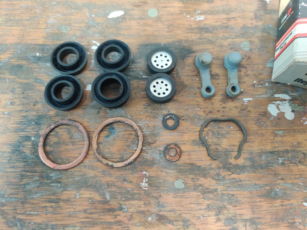
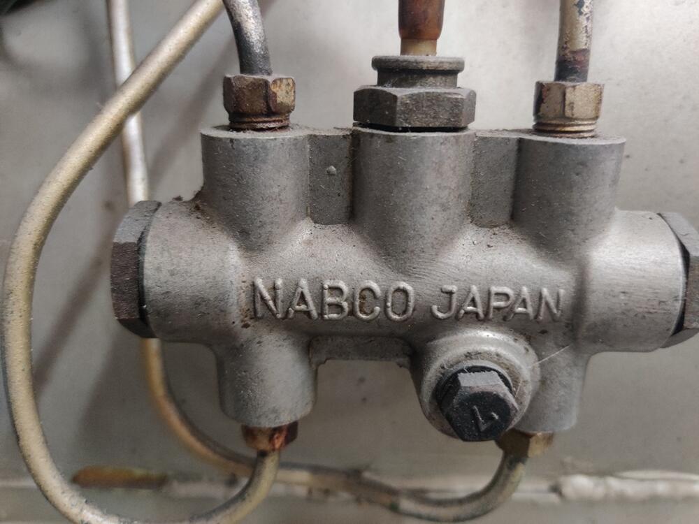
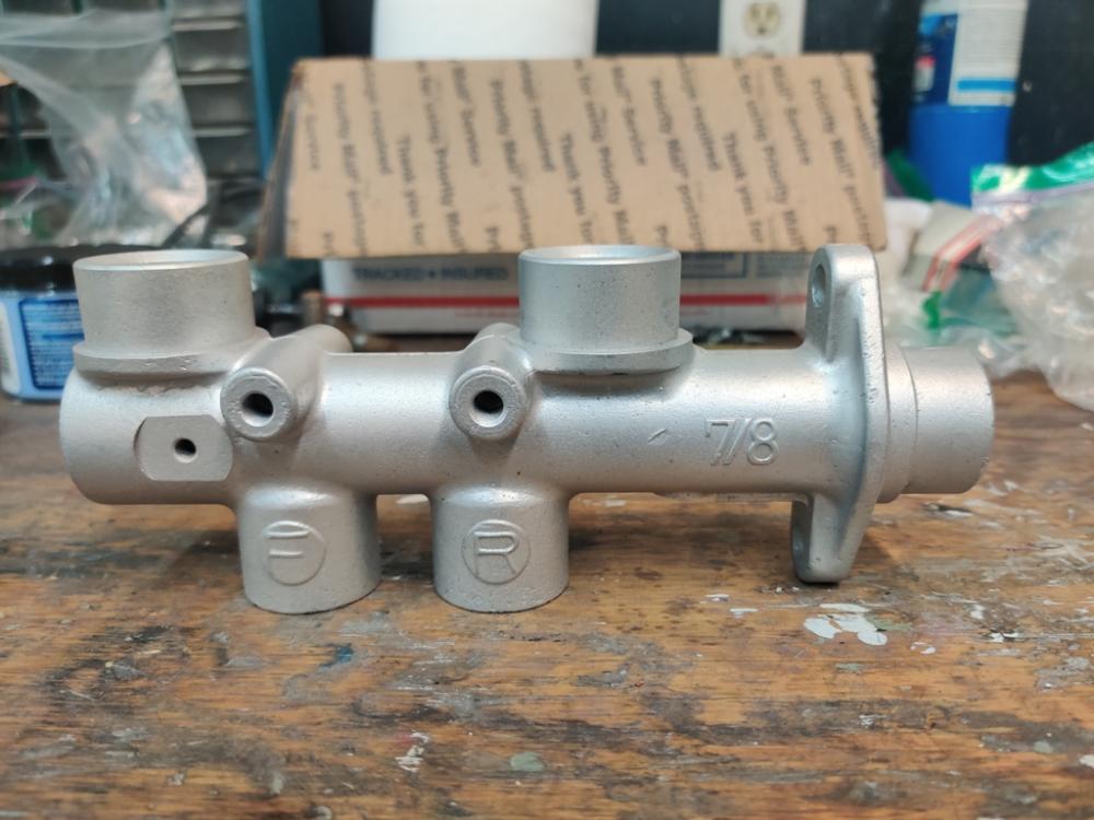
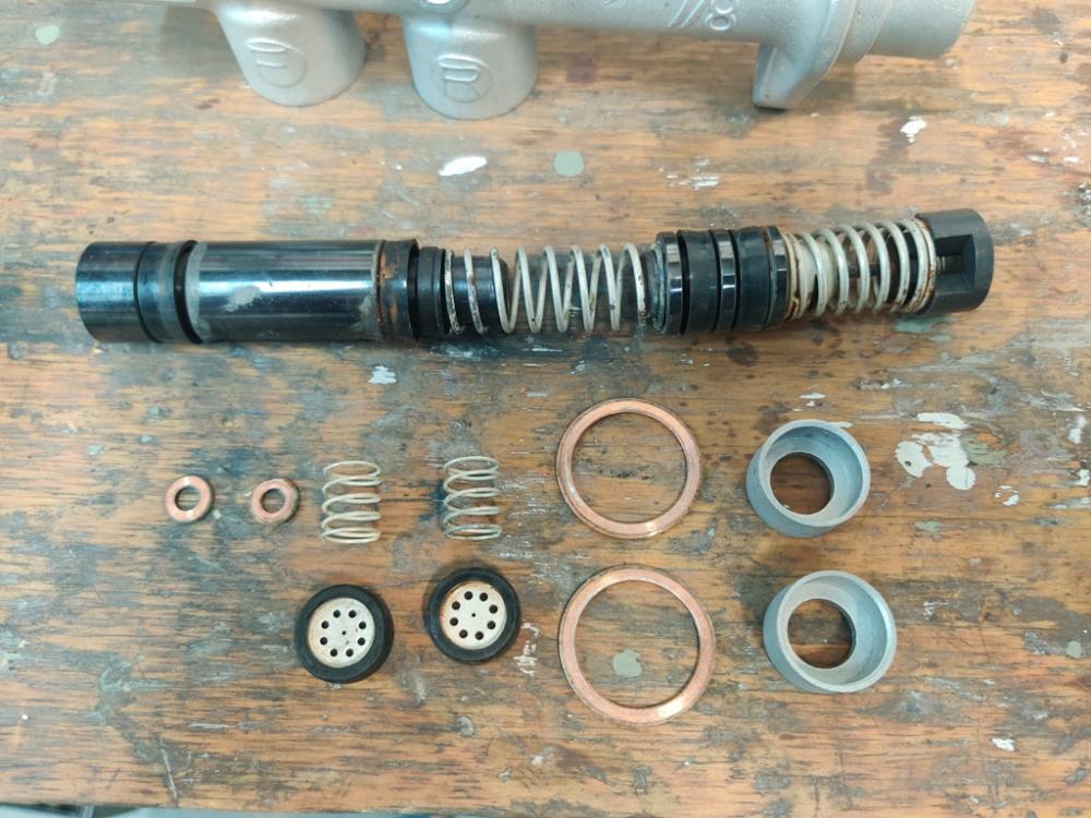
It took a while for me to notice, but the master cylinder which came mounted in the engine compartment of the car I am restoring is actually the "later style" which is "incorrect" for the restoration I am doing. It is this one which is for 240z's from 9/1971: http://www.carpartsmanual.com/datsun/Z-1969-1978/brake/brake-master-cylinder/from-sep-71 The one which was original on my car (6/1971 production) is this one: http://www.carpartsmanual.com/datsun/Z-1969-1978/brake/brake-master-cylinder/to-aug-71 I was able to source one off of eBay that is in surprisingly good shape and I happen to have an old rebuild kit for it which I bought back in the early 1990's: My question is this: given the front and rear circuits are reversed between the two, what do I have to do, precisely to put the original brake master cylinder back in the car so that the circuits are matched up properly? Or, asked another way, what is typically done to fit the later style cylinder to the earlier car? I note that these earlier style MC's are nearly unavailable now. So, I am guessing that people are frequently putting the later style in the early cars at this point. I found one relevant thread by searching, but it doesn't have quite the info I need.

-
I came across this video recently and was intrigued. I haven't tried this yet.
-
That is fine. As far as Randy goes, I'd just like to stop by and have a look at his cars for an hour some day.
-
His place is near me evidently. I need to investigate and go check it out.
-
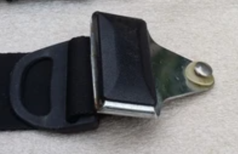
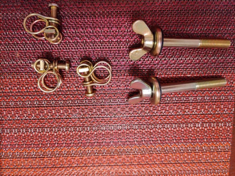
Updated list: New: Seat belt - black plastic cover for buckle clip (see pic) (or will buy belts with these buckle covers:) Also, need one black plastic loop like in this picture as well: Still needed from my original list: original radiator without automatic transmission fittings - need upper and lower tanks/caps to be usable Seat recline knobs (not cracked) -- item #6 in the picture here: http://www.carpartsmanual.com/datsun/Z-1969-1978/body-240z/seat-slide/type-1-adjuster-seat/6 metal engine fan blade assembly and possibly mounting hardware Amco - aftermarket rubber floor mats 4 pieces of rubber trim originally glued to corners of tool door compartments (these compartments are in the front of the rear hatch deck/floor area) original 14" Bridgestone 175HR14 RADIAL RD-150 spare tire. Prefer DOT code of (check DOT code on tire) "221", "231", "241" or "251", but let me know what yours is original carpet padding "jute" (brown horse hair like stuff). This "jute" was originally installed under the front floor carpet mats, under the seats, under the center tunnel diamond textured vinyl trim, and under the carpet in the rear hatch deck/floor. This stuff is fragile, and it would be nice, if you have any that is in good condition, to take some care with removal (it was glued to the tunnel) and care with packaging for shipment. Removal with diamond patterned vinyl trim/cover still attached (glued) to the top side of the jute would be preferred. 4 original hubcaps for a 6/1971 240z (early style) battery cover (the plastic related parts) for 1971 240z original scissor jack and related red painted jack tools, yellow wheel chocks and black vinyl tool bag. I am looking for some in really nice condition. There are letters stamped into the base of the jack that need to start with the letter Q (1971), and then be followed by F (June) as the second letter, then followed by A through Z or AA through EE as the third letter. As best I can tell, I need a jack with any of the following stamps: (QFS, QFT, QFU, QFV, QFW, QFX, QFY, QFZ, QFAA, QFBB, QFCC)
-
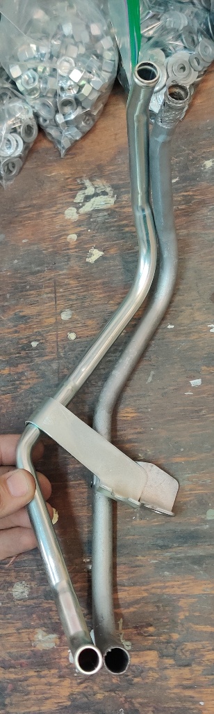
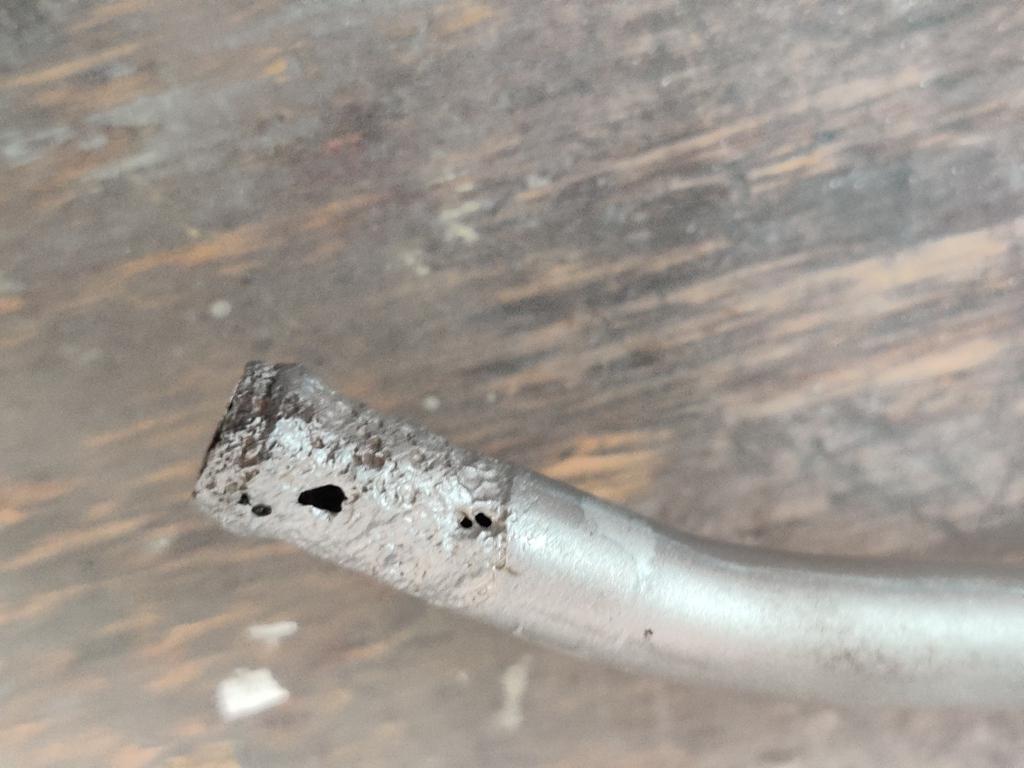
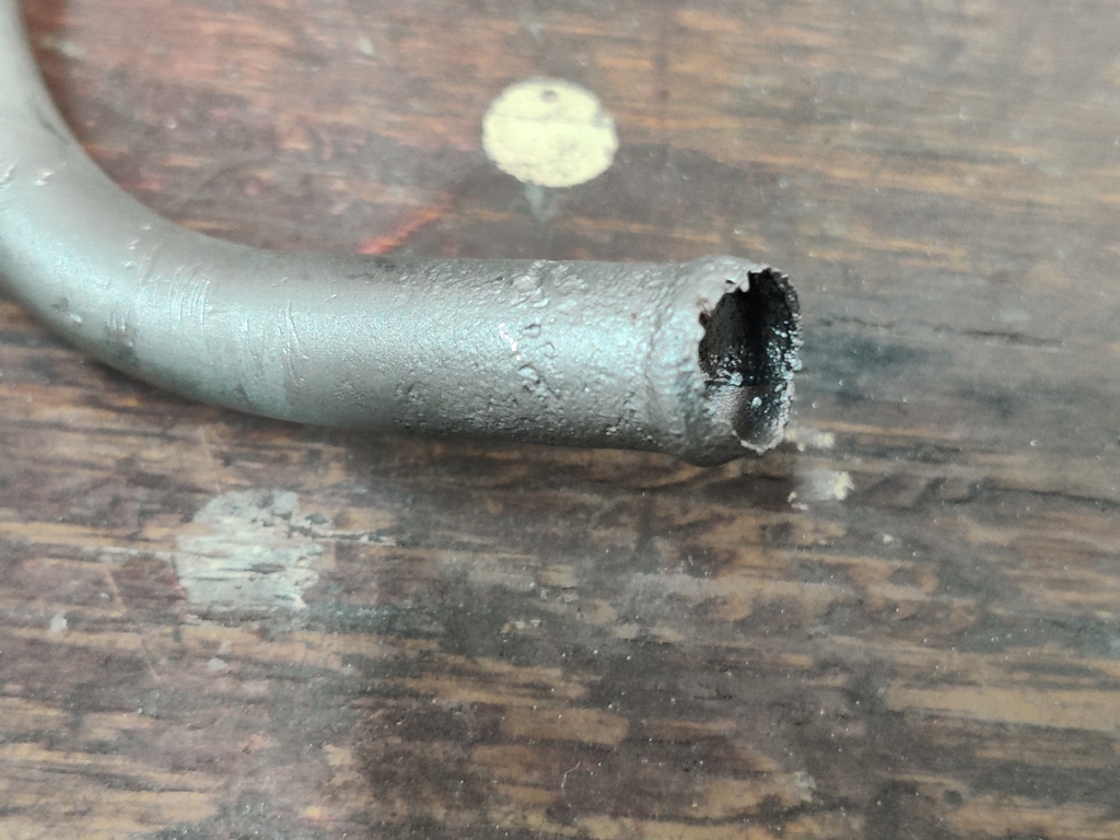
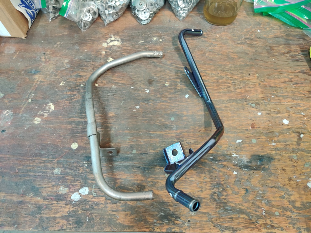
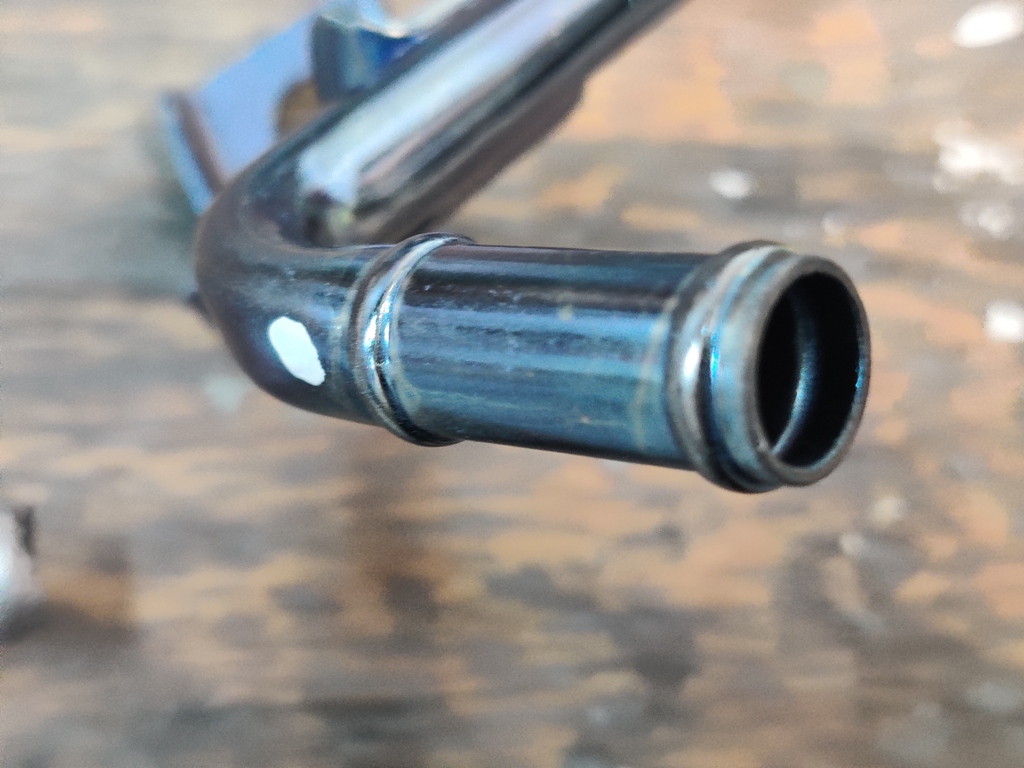
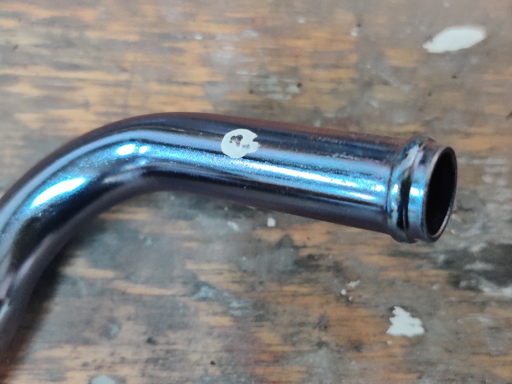
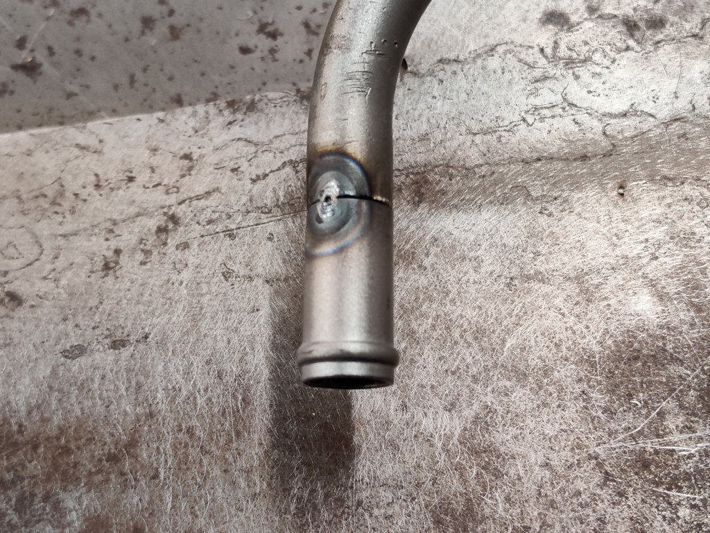
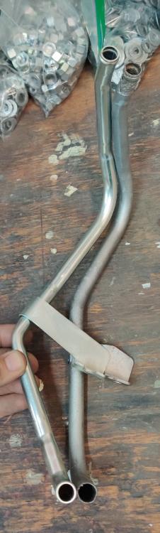
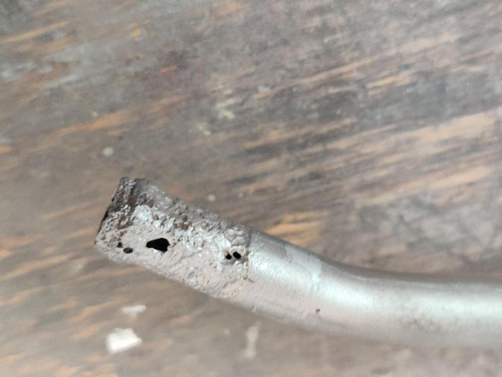
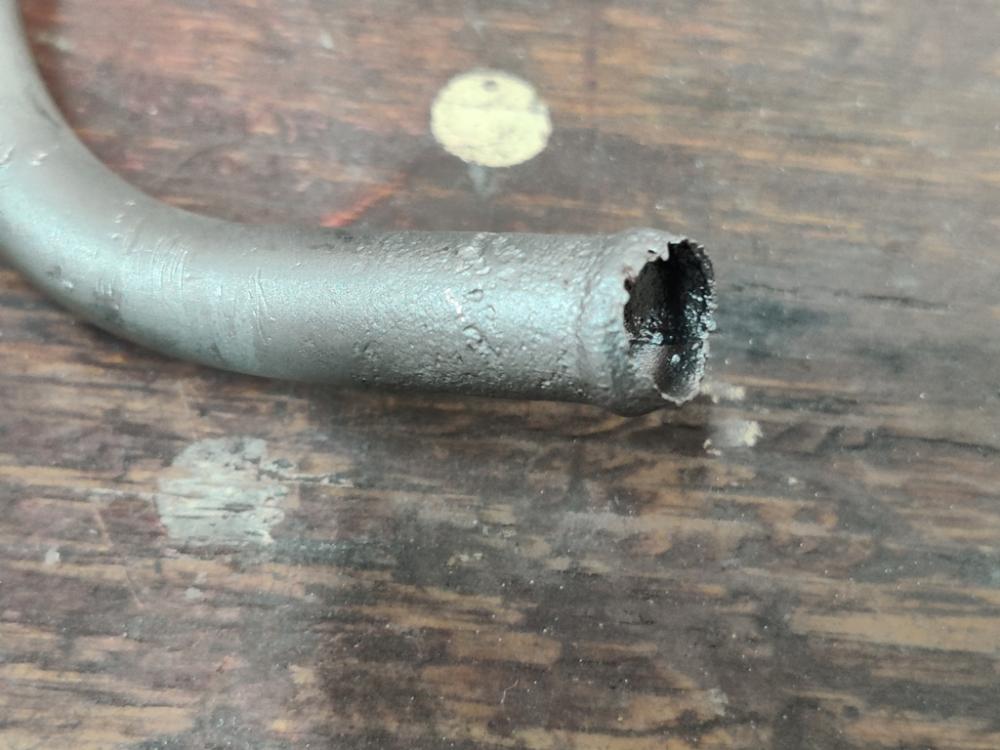
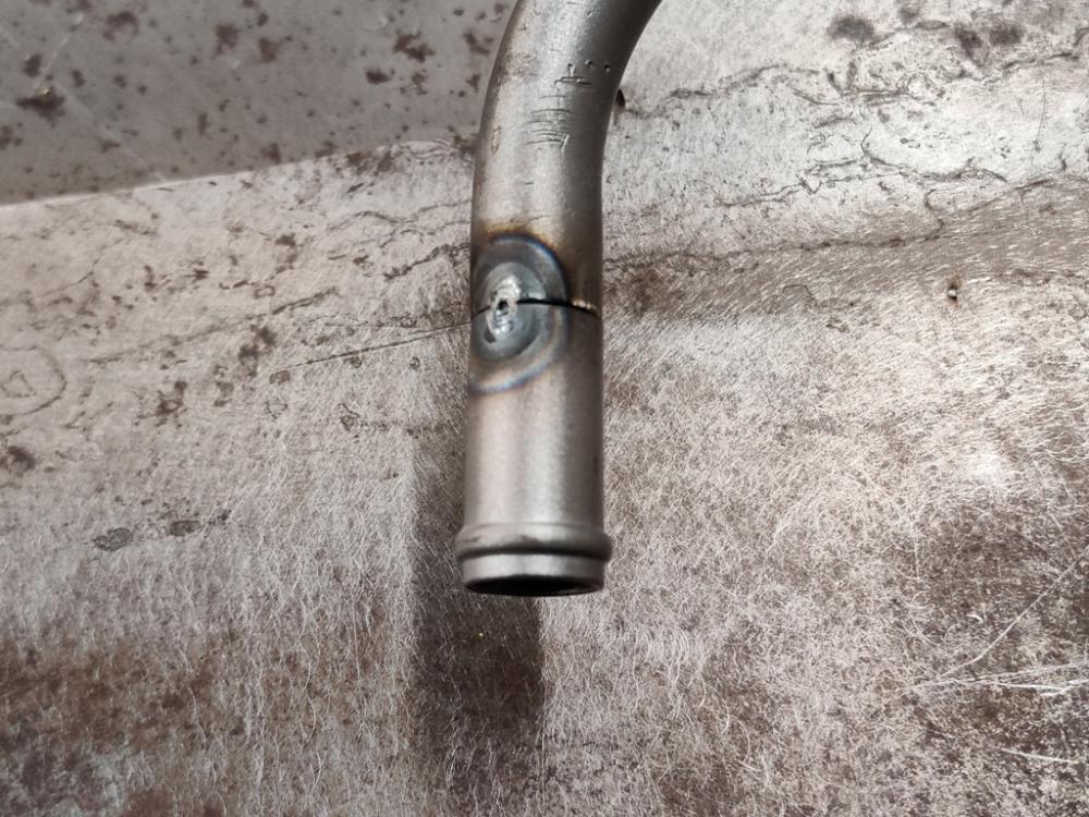
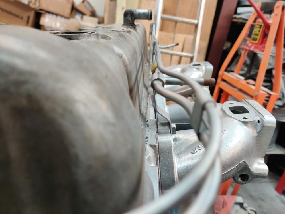
The work to prep the hardware for plating is laborious. Also, I have been trying to make sure I track down every last piece of hardware. The car was not fully assembled when I bought it, so trying to identify everything is difficult and time consuming. I am having some repeatable success with my hardware prepping process. Basically it involves bead blasting to strip, stainless media in the vibratory tumbler to remove the glass bead finish, and corn cobb metal with a metal polish in the vibratory tumbler to polish the parts followed by a Dremel tool with wire brush attachments and sometimes #0000 stainless steel wool to make the finish more consistent after the dremel wire wheels. I got a wire wheel attachment for my 8" bench grinder and gave that a shot for a few seconds. In addition to scaring me because I think it will take a body part off, it is way too aggressive for cleaning hardware. Oh well, only about $15 and will certainly come in handy for something. I thought I would share what I found out about the water pipe that goes around the back of the cylinder head. First, I bought the one that Motorsport sells. As you can see in the picture here, where I compare it to my original, it is quite different. The bracket is much taller. So the pipe is different to match. It would probably work, but I had an idea to fix my old one. Basically, the old pipe is in good condition except for the part where the hoses attached. Under the hose, the pipe corroded quite severely. Figuring that some modern Nissan would share a similar part, I went looking using image search on Google and came across a part that is not too expensive (about $25) that has what I need - good ends. It is a Nissan/INFINITI 14053-EA20B Engine Coolant Pipe (pictured on the right in the third pic here): It is the same diameter and has enough straight length for me to rob what I need off of it. I cut 25 mm off of each end and off of my old one. Then I decided to break in my Tig welder, which I bought 1 and half years ago - 😦. I know... right! Well, I finally overcame the trepidation of the learning curve and got it fired up. I practiced on the carcass of the new pipe for a bit and then managed to get two tack welds to hold one of the new ends on. I will practice some more on the sacrificed pipe before I finish weld the new ends onto my old one. I will test it for leaks of course. I think it will look really nice when I am done and have it prepped to be re-plated.


-
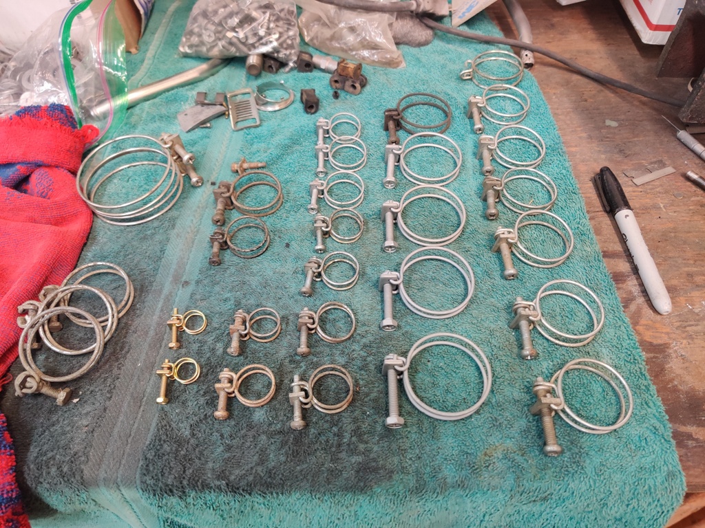
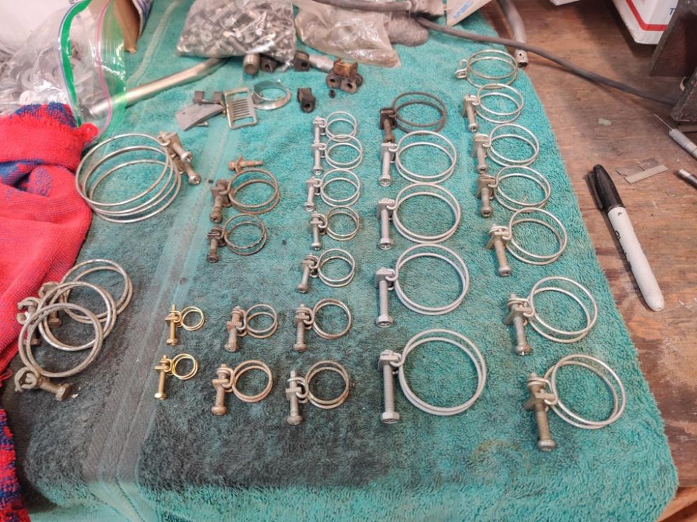
Most of my spares. Note that the ones which are dull grey are newer oem ones with the hex head. However, I have many here with the correct pan head and those screws can be swapped. Left-most are too big in diameter or wrong style. I need to know what diameter you are looking for specifically. The two gold ones are the newer style with hex heads, but I believe I have the proper screws in the right size to swap to those clamps. The four grey ones in the second column from the right look about right for the radiator, and I know I have the proper screws for those. You would need to send these off for re-plating in zinc (clear - which is silver in color) if you want them to look like factory.
-
Yep. They were originally silver, and I will be re-plating mine to silver instead of gold. Jim, if you confirm fuel pump clamp style, let me know. I have many different size OEM clamps in silver that I stripped from Datsun's years ago.
-
Yep. They are.
-
I may have what you need, both fuel and otherwise. Do you have an original fuel one to look at? They differ in style from the larger clamps. Here is what the ones on my car's fuel lines look like, though they were silver in color from the factory:
-
Attention grabbing for me for my restoration. Some number of fasteners is missing - I need to find and add. I will clean it up a bit as I progress on it. 🙂
-
I have been working on documenting the fasteners on the car. When I finish all of the documentation of the hardware, I will upload a worksheet to the resources section. In the meantime, anyone with a google account can access what I have so far by going to the link: Datsun 240z hardware - 6/1971
-
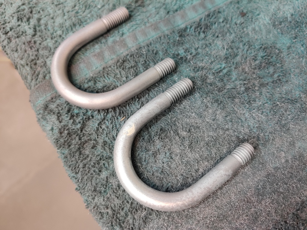
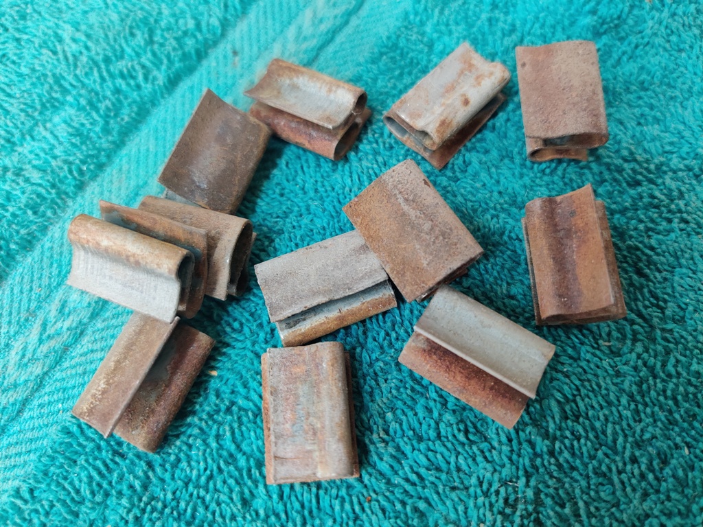
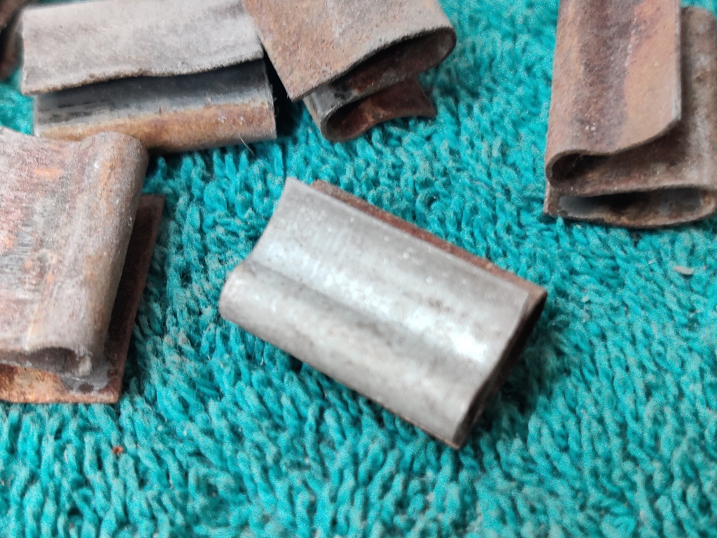
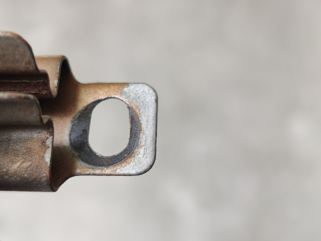
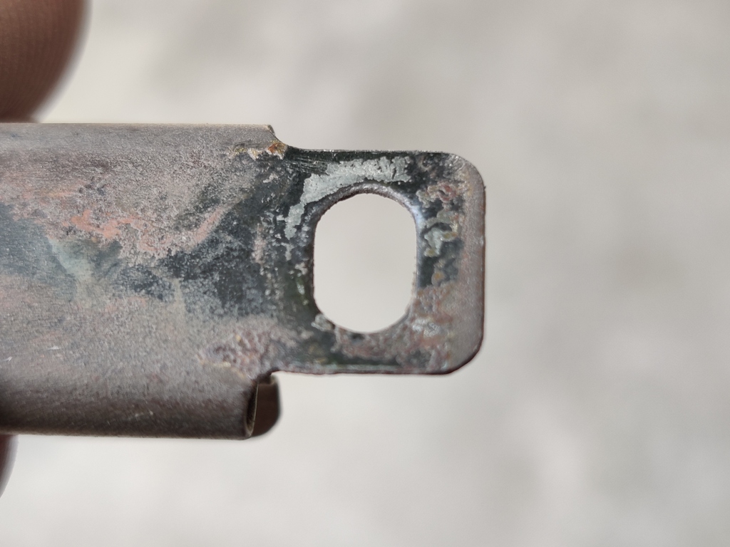
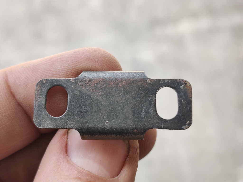
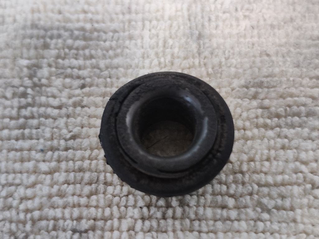
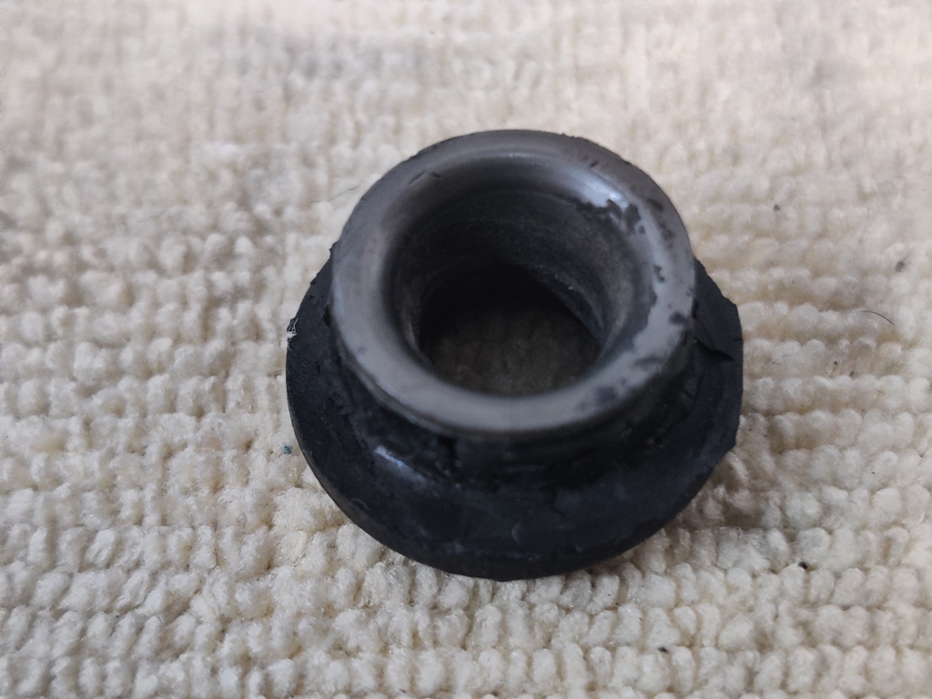
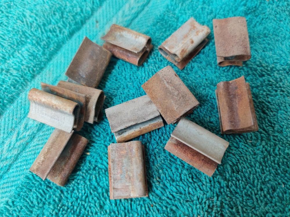
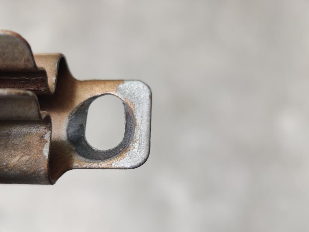
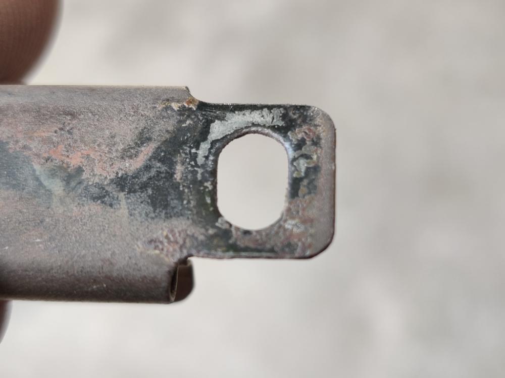
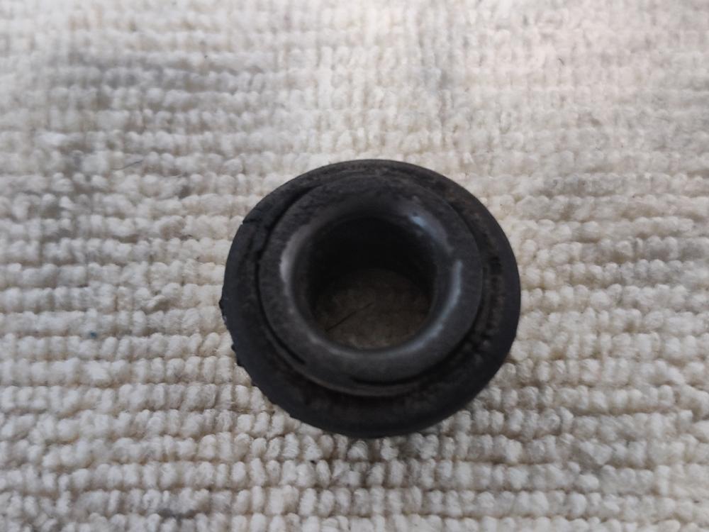
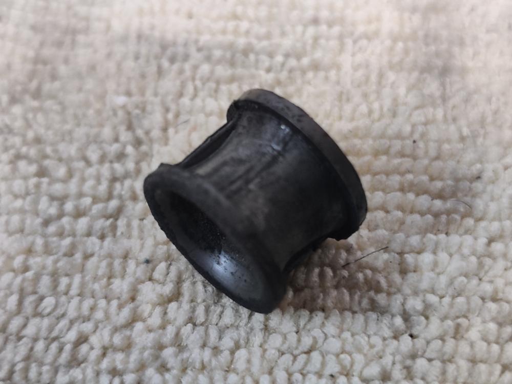
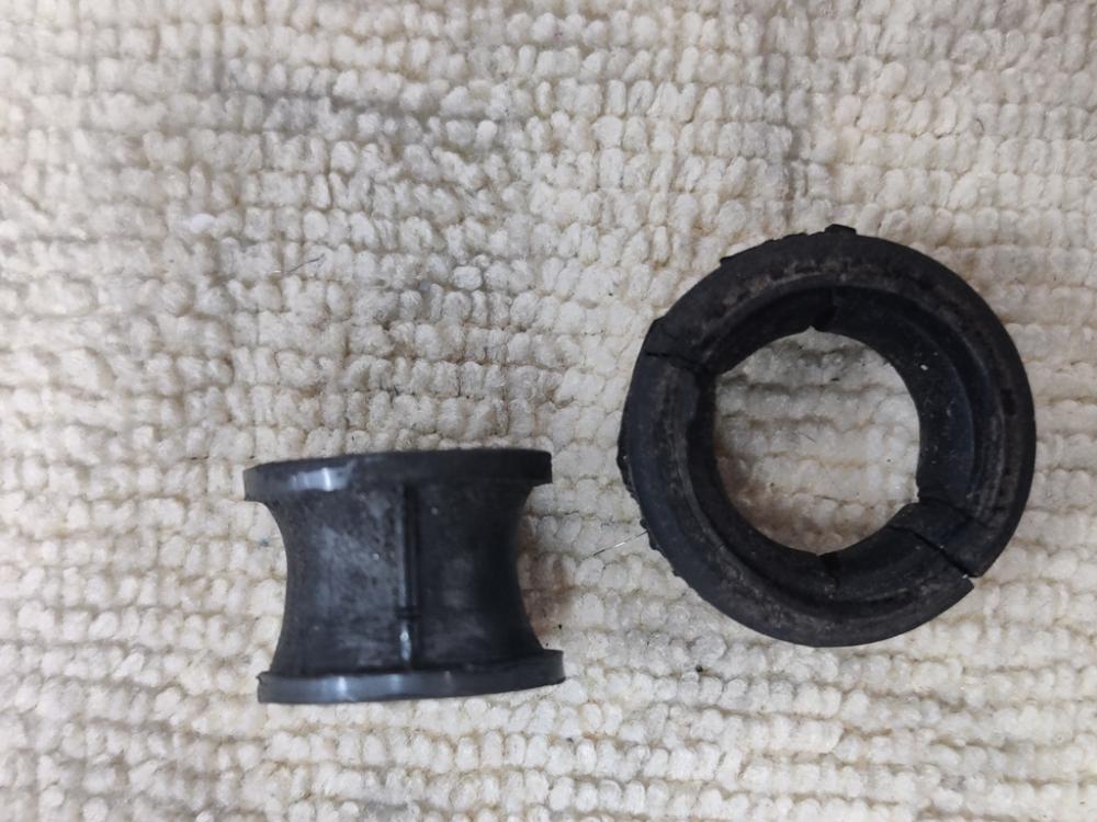
I see it has been a long time since I posted an update. I am still working on fasteners. I suspect that I am putting too much time into them, but I have no experience with getting hardware replated. So, I feel I can't leave it up to chance. I will probably send some "test" hardware along with it in various stages of prep or lack thereof. It will be interesting to see how the test hardware compares to my fully prepped hardware. I have a few observations to share, but not much of an update. First, the u bolt that holds the steering rack from twisting on the front crossmember - I happen to have two. There is a white blot of paint from the factory. I noted that under the white blot, the part was silver. So, this part seems to have received zinc plating (clear) from the factory. The clips that secure a rubber weather strip to the unibody under the top of the fender, here in their as removed condition. Amazing that they don't even have rust on their entire surface: The battery inspection panels have these metal clips. I find it interesting that they received a black coating originally that is not paint. This is actually consistent with other black plated parts I have found on the car. Black parts are, nearly without exception, springs or springy. The bushing in the bracket that bolts to the engine compartment firewall, which supports the back of the main throttle rod, is always rotten on any 240z. It is a two piece bushing, with a plastic inner barrel and a rubber outer grommet. The rubber part broke when I pried it out of the bracket. Here it is temporarily put back together: First pic has half of grommet removed. Middle pic is of the plastic barrel by itself. I will be trying to source a similar bushing from McMaster Carr. And lastly for today, I find it interesting that the hatch hinges were bolted into the car when it was painted at the factory. The odd part about that is that the rubber enclosure was in place also. My car had shims on the right side hinge only, and you can see by the original paint that they were in place when the car was painted. This, and the fact that the taper head bolts that hold the hatch to the hinges were not originally painted, tells me that the hinges and hatch were bolted to the car for fitment, and then the hatch was removed (the four taper head screws only were removed) for the original paint application at the factory. Also, hinge assemblies and shims were clear zinc, and backing plates were yellow chromate/cad. I think I am nearing the end of the great fastener round up and restoration of 2020/2021. I ordered some new ones a couple of days ago to fill in for the small number of originals that went missing at some point. I am digging through my boxes of old Datsun hardware to find suitable replacements also. I am having some success there, finding matching hardware with 4's and 7's and 9's on the heads of bolts - proper style and length. Yeah... I am more than a bit OCD I think.


-
Thanks for that. I see differences in the brackets. I will work on mine more and make it look like that one.
-
Different somewhat, probably because it is a series 1 car, but this one looks really good (and likely original) to me compared to many I see on previous BAT (Bring a Trailer) cars. https://bringatrailer.com/listing/1970-datsun-240z-65/ (around pics 62-67)
-
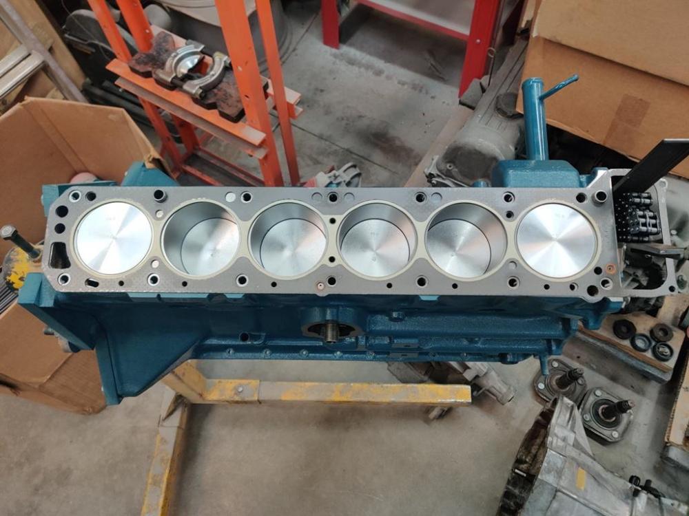
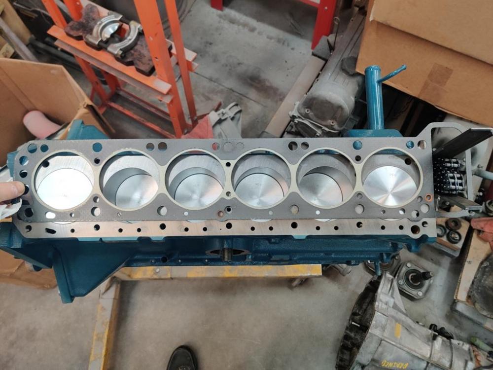
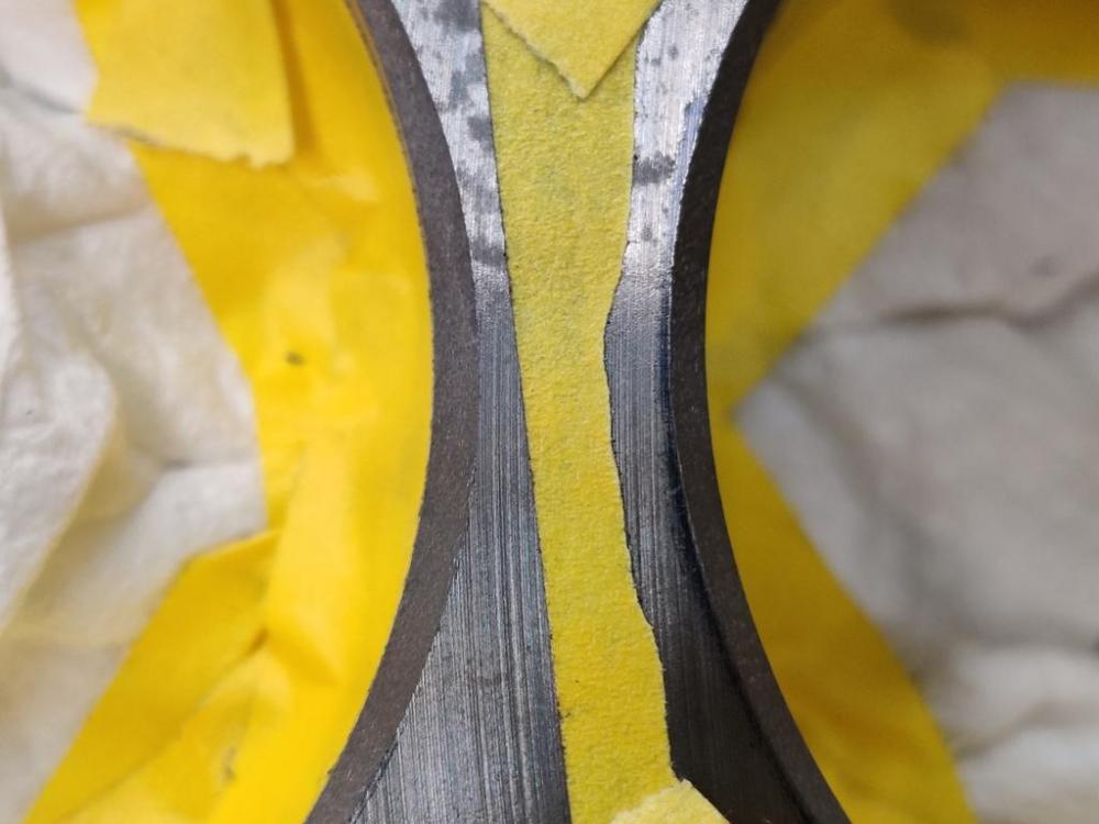
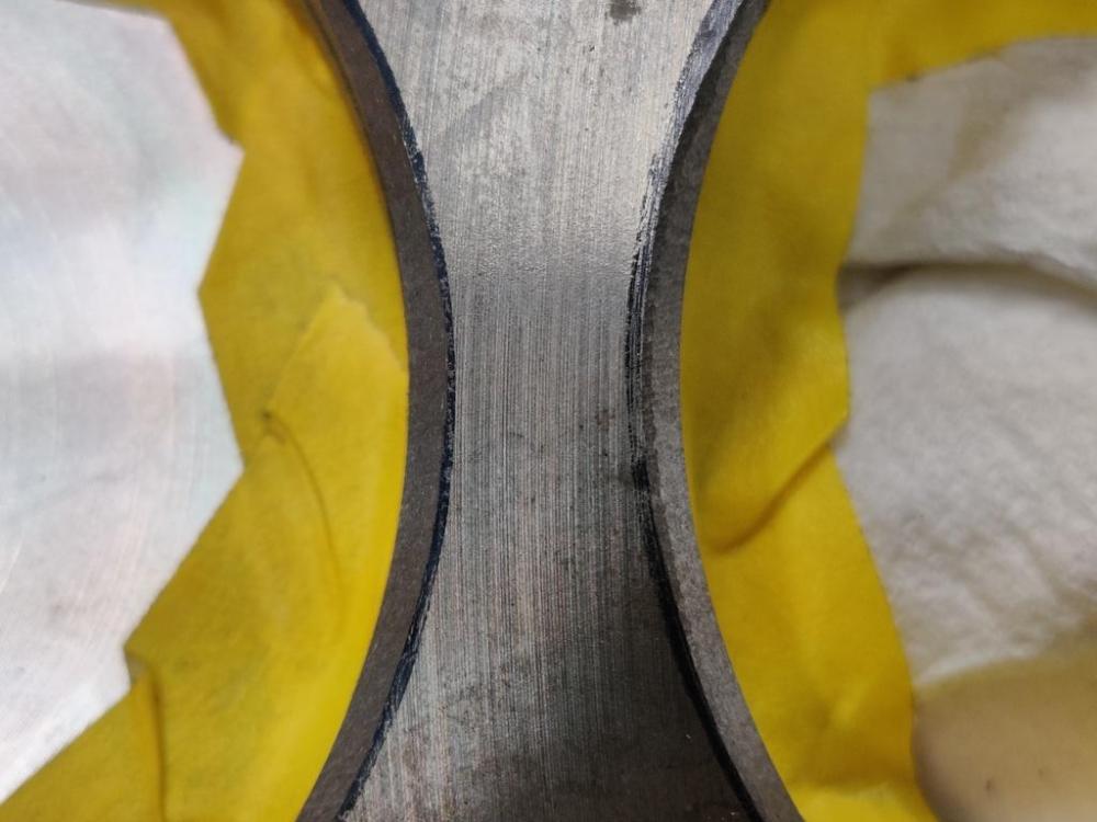
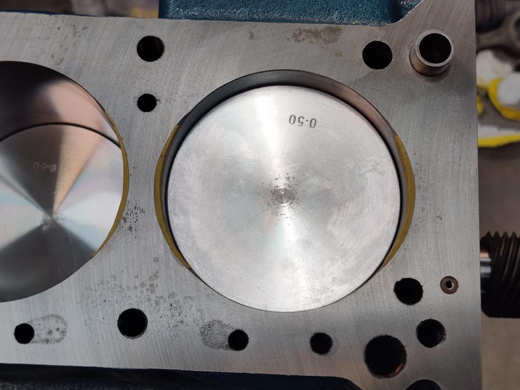
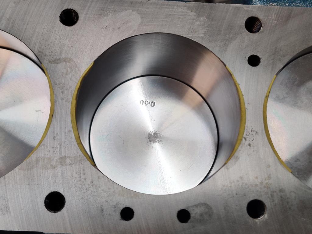
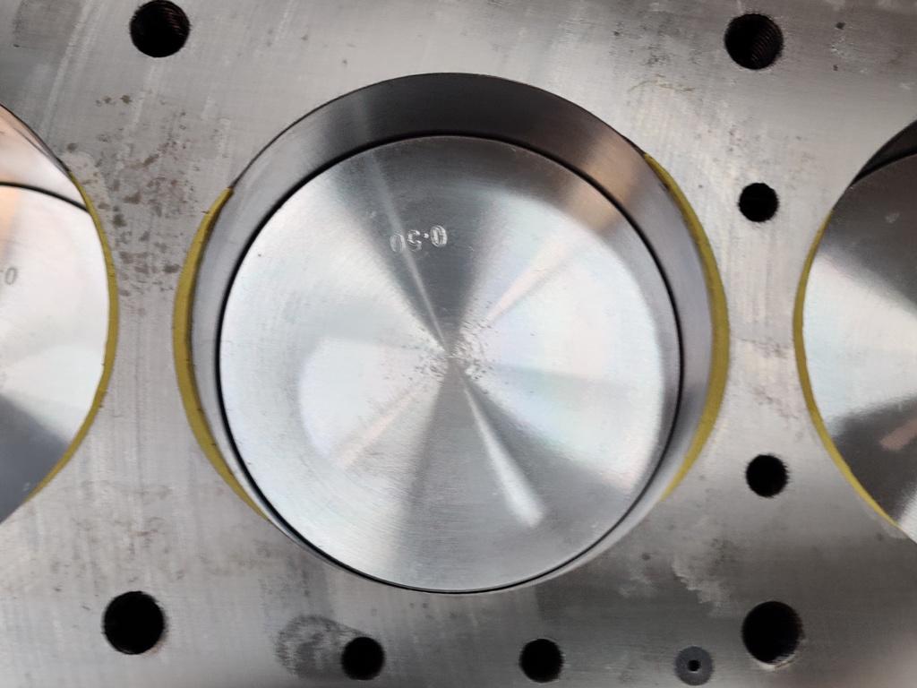
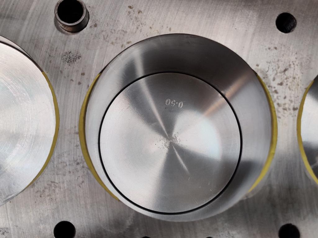
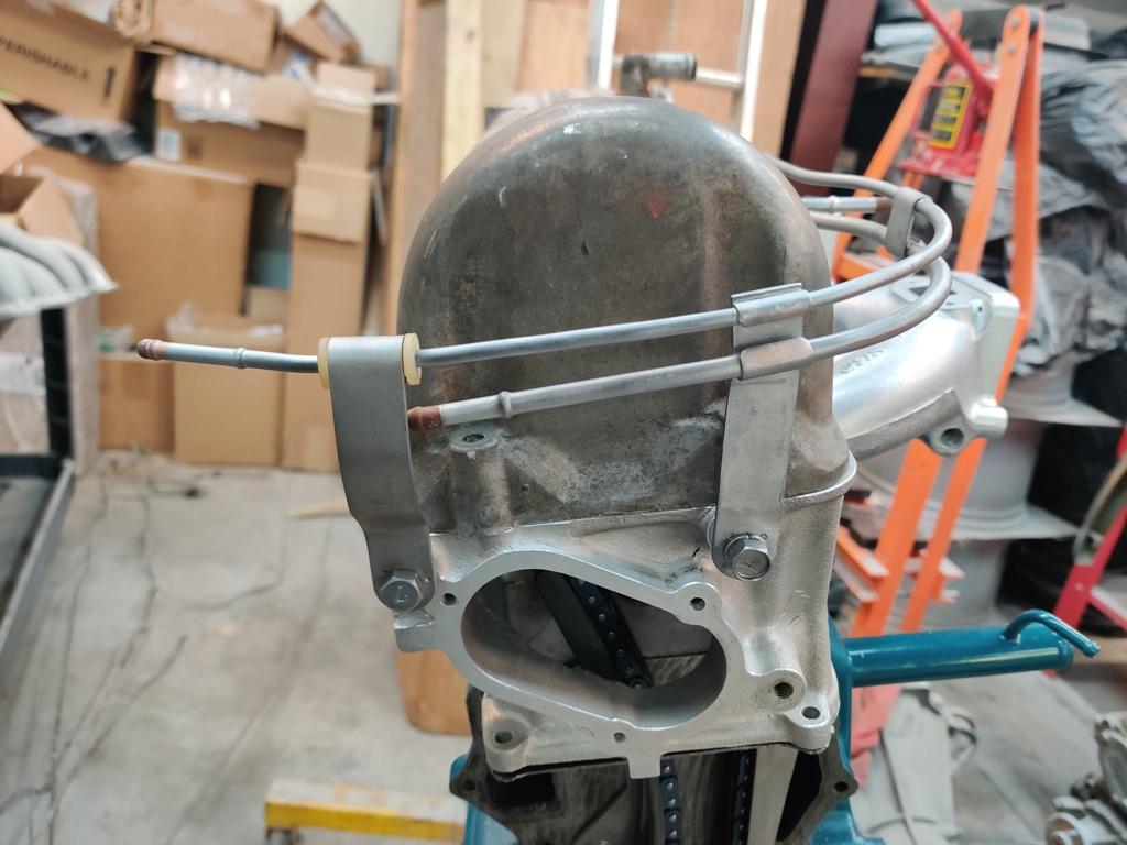
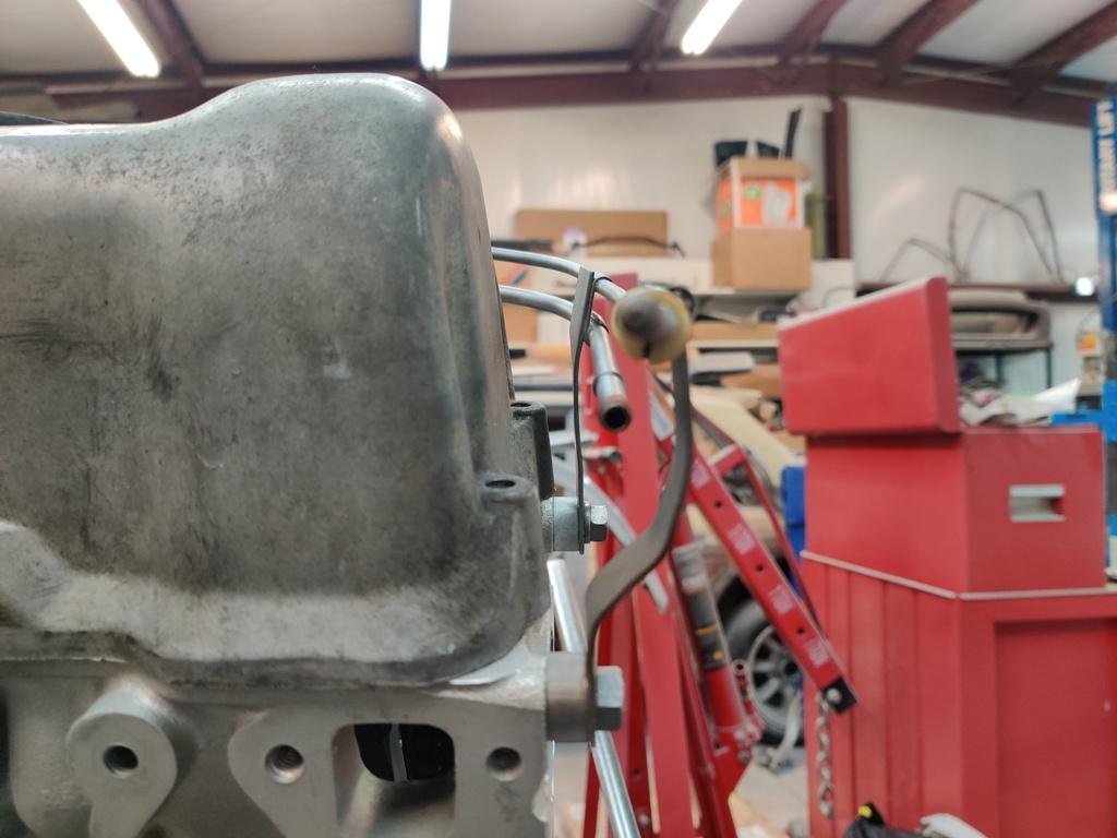
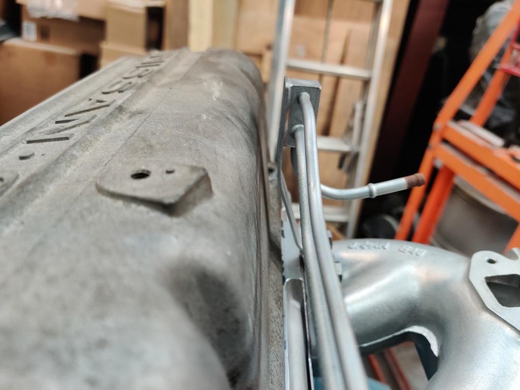
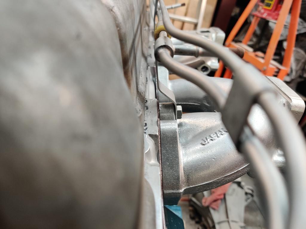
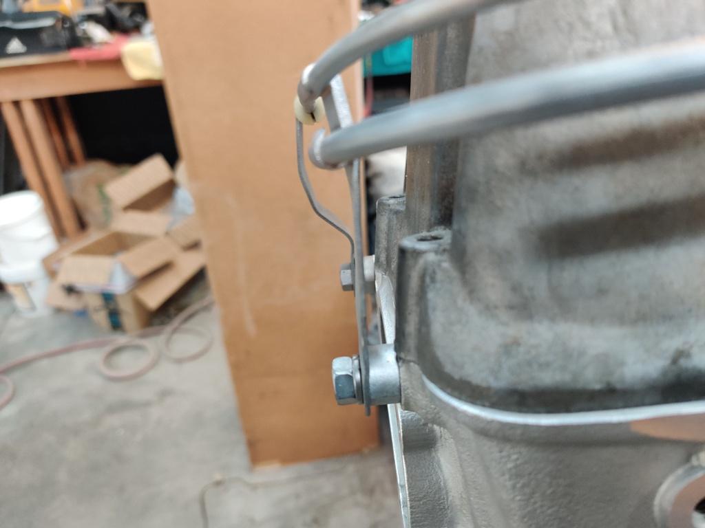
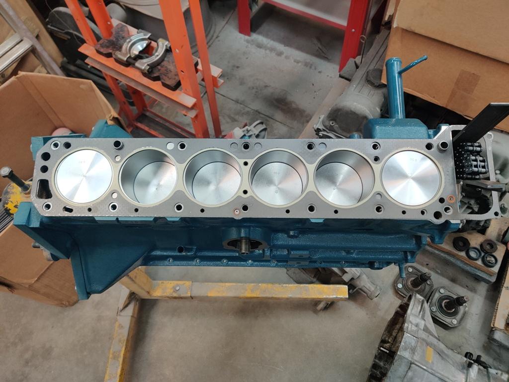
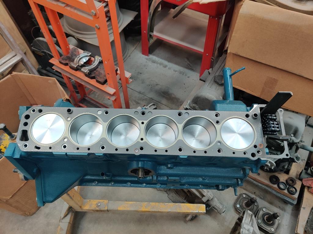
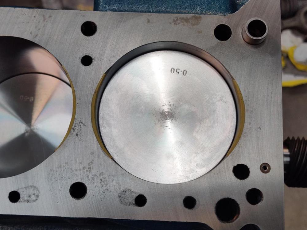
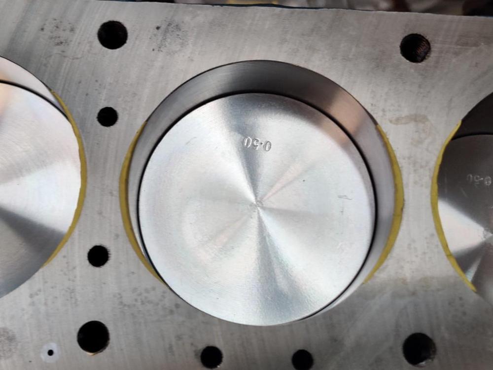
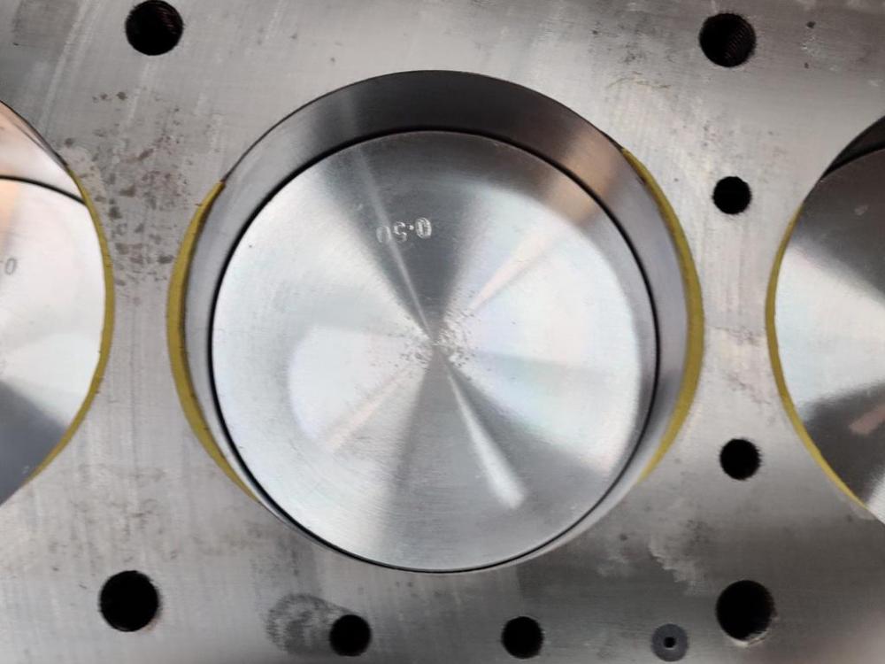
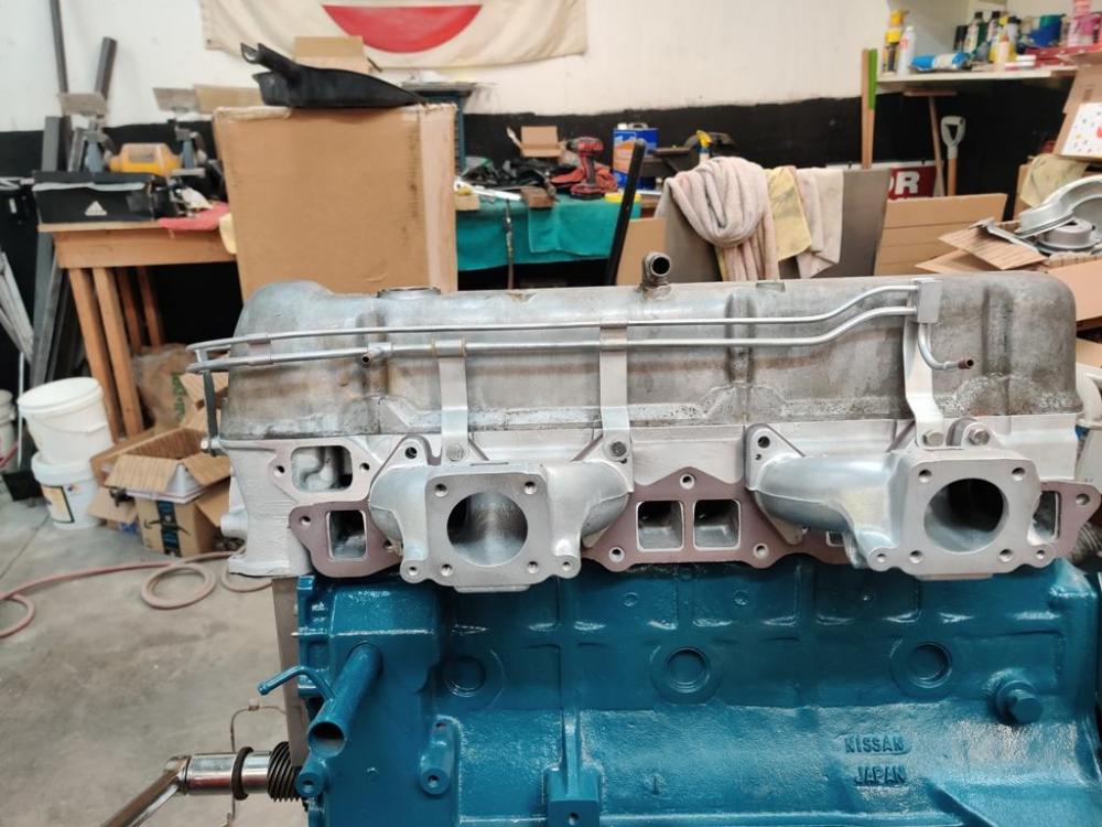
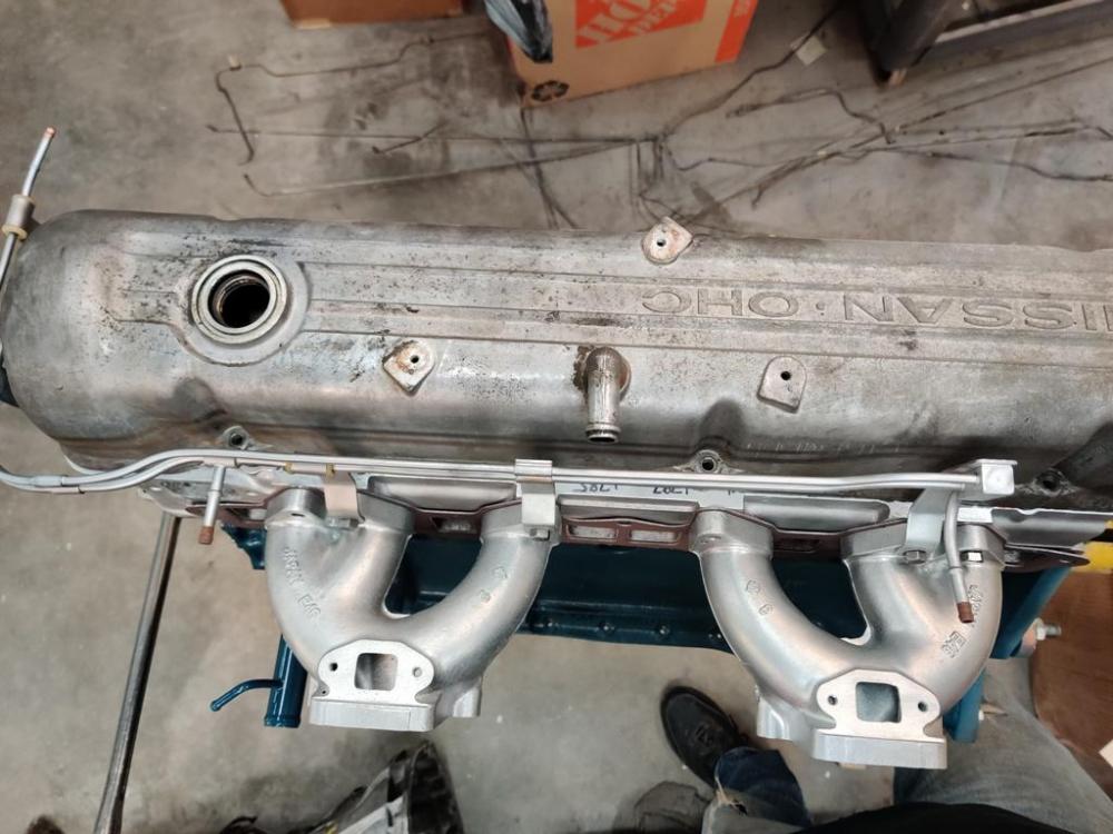
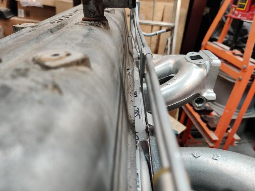
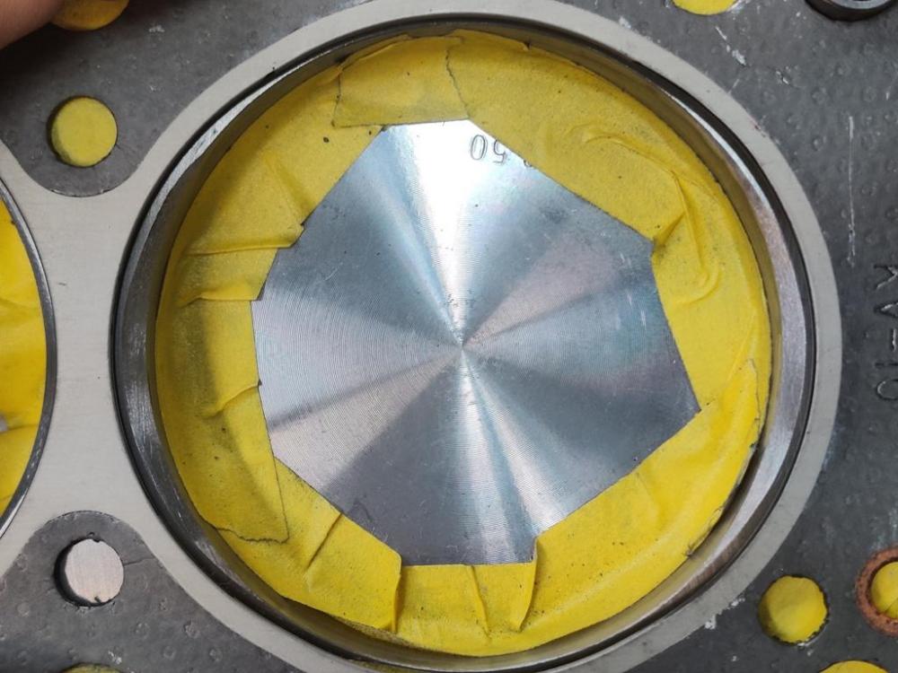
I added clay to replace the material that was removed from the bores for eye-browing the block. I then put the head gasket on, lightly bolted the head on, and ran the engine through revolutions to check for valve interference. When I took the head off, there was none that I could perceive - there were no marks in the clay. Of course, this engine is bored over a bit, so there was that chance before mocking it all up that they would not hit. 🙂 After checking that, I pulled all of the clay off and combined it into one piece which measured out to less than 1 cubic centimeter. So, compression ratio is not significantly reduced. Some pics - Cylinders 1-6 in order: Additionally, my fuel line assembly was pretty bent up, so I put it on the engine in a mock up fashion and worked on straightening it for an hour or more with a crow bar, vice grips (with wood stirring sticks used for protection from marks), and a hammer. It looks ok now, but I wonder about the brackets, if they are near original in appearance, or if they are quite bent still. The parallel aspect of the two lines seems pretty good to me. The brackets dictate the height of the lines along their lengths without much variance. I want to be sure the shape of the lines in the assembly is all sorted out before I send it off for re-plating.


-
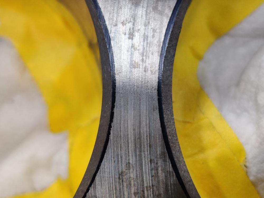
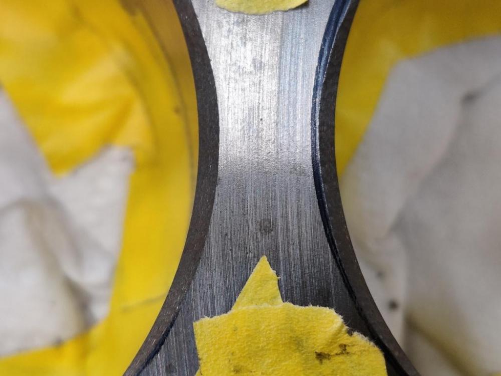
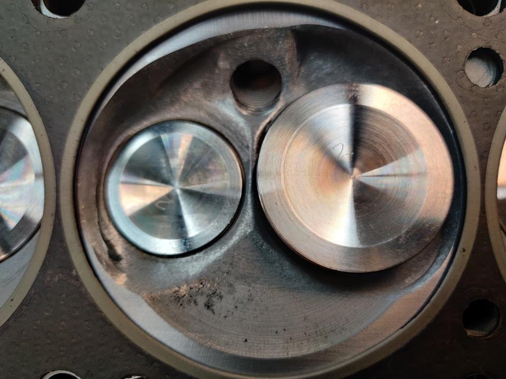
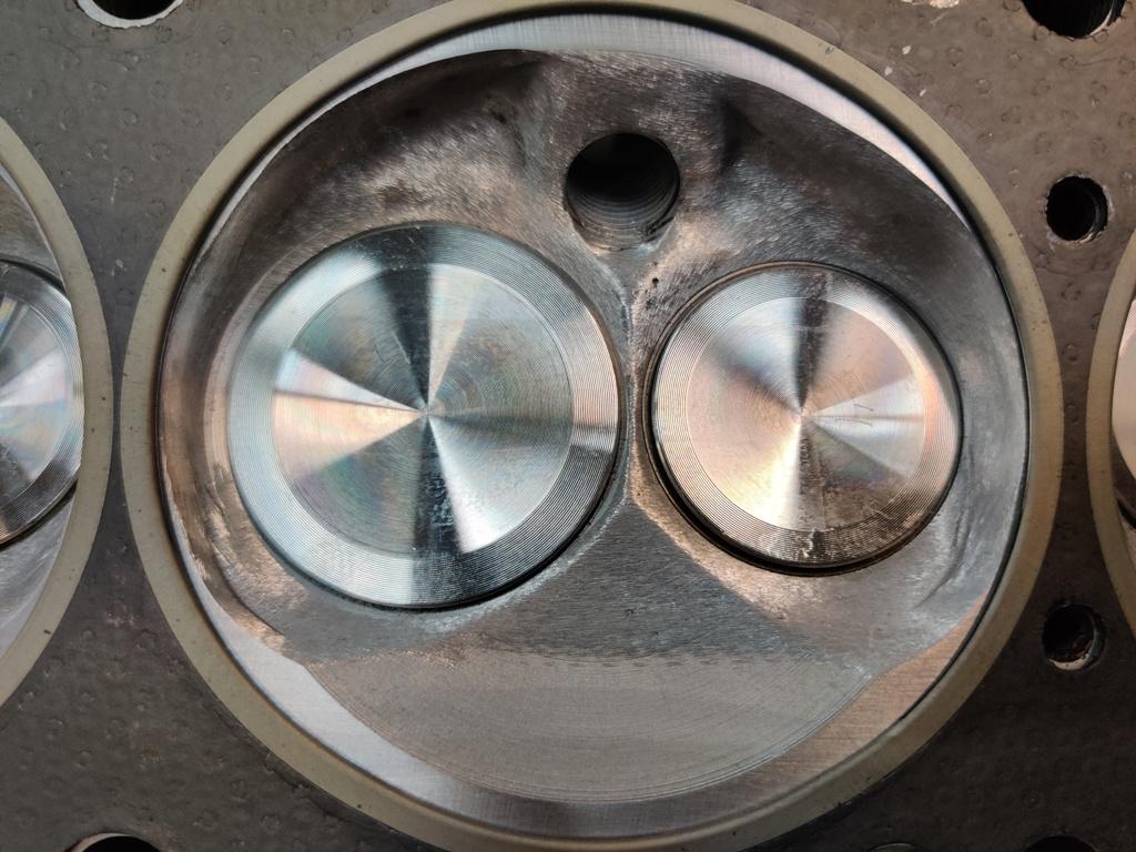
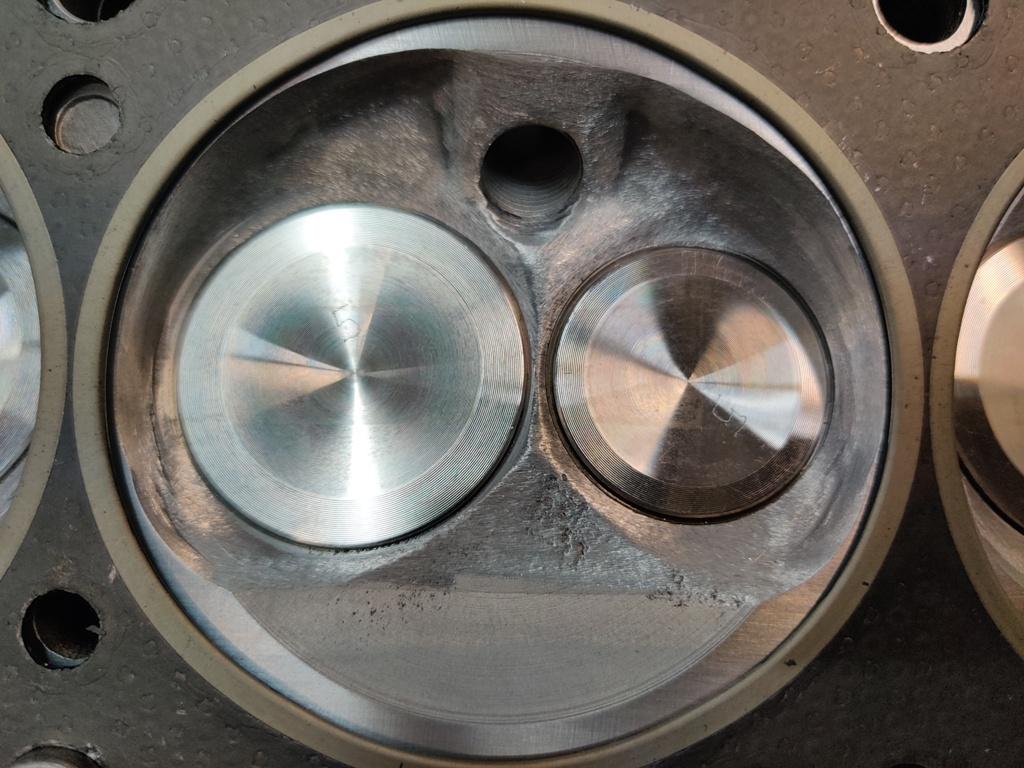
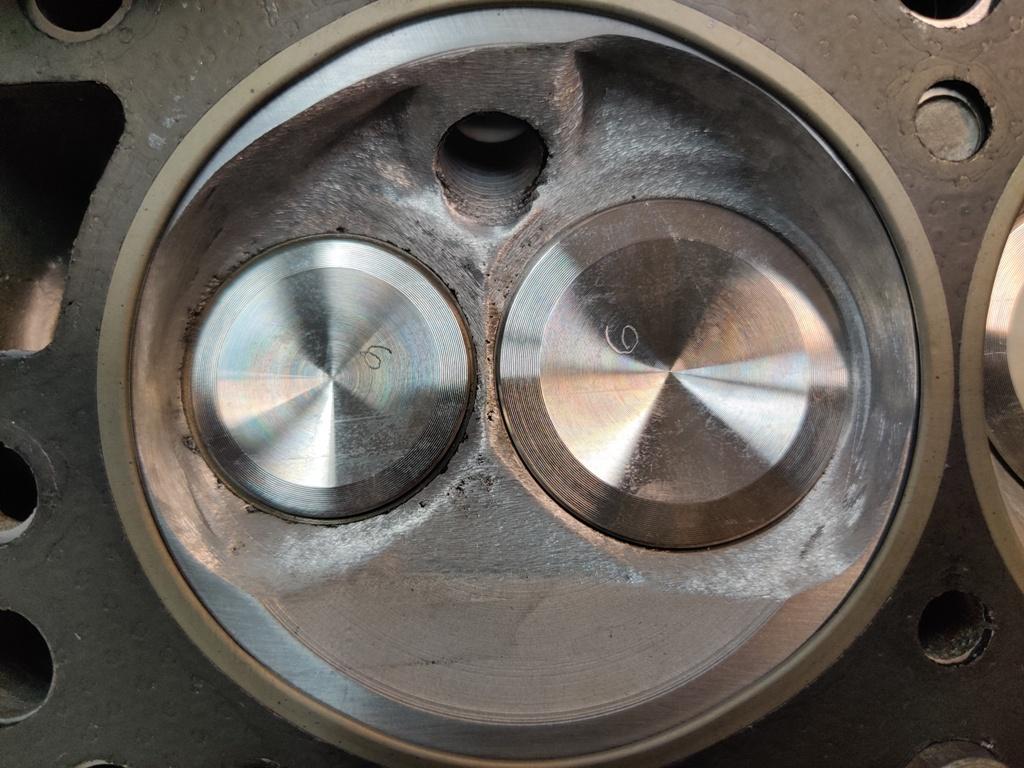
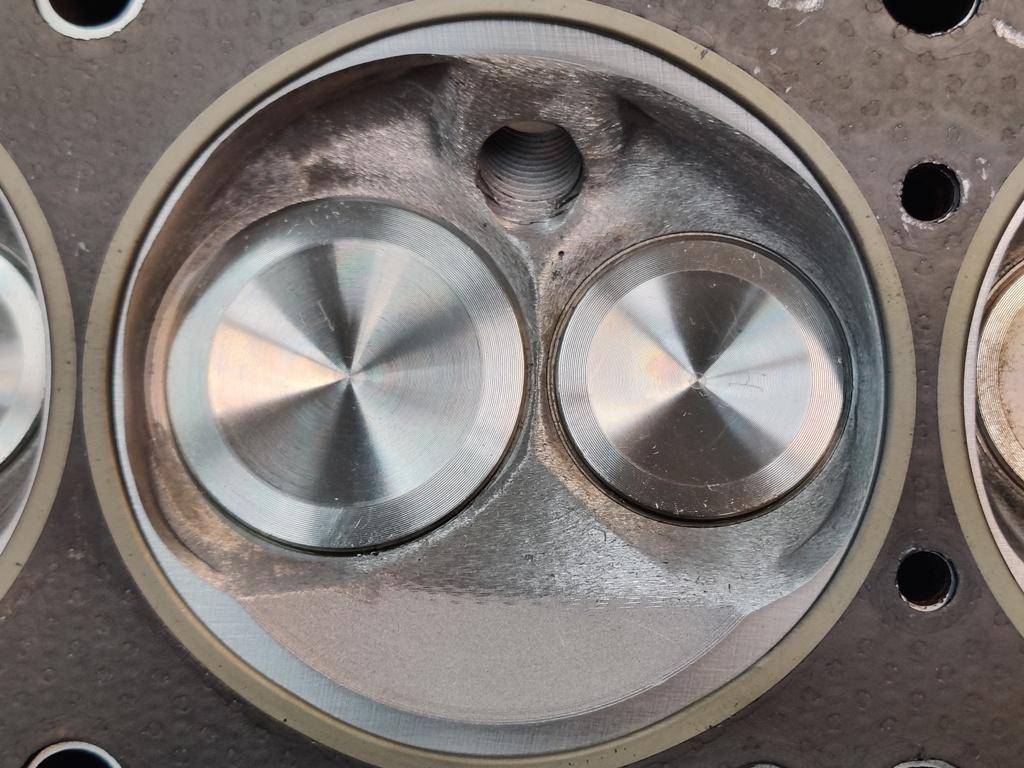
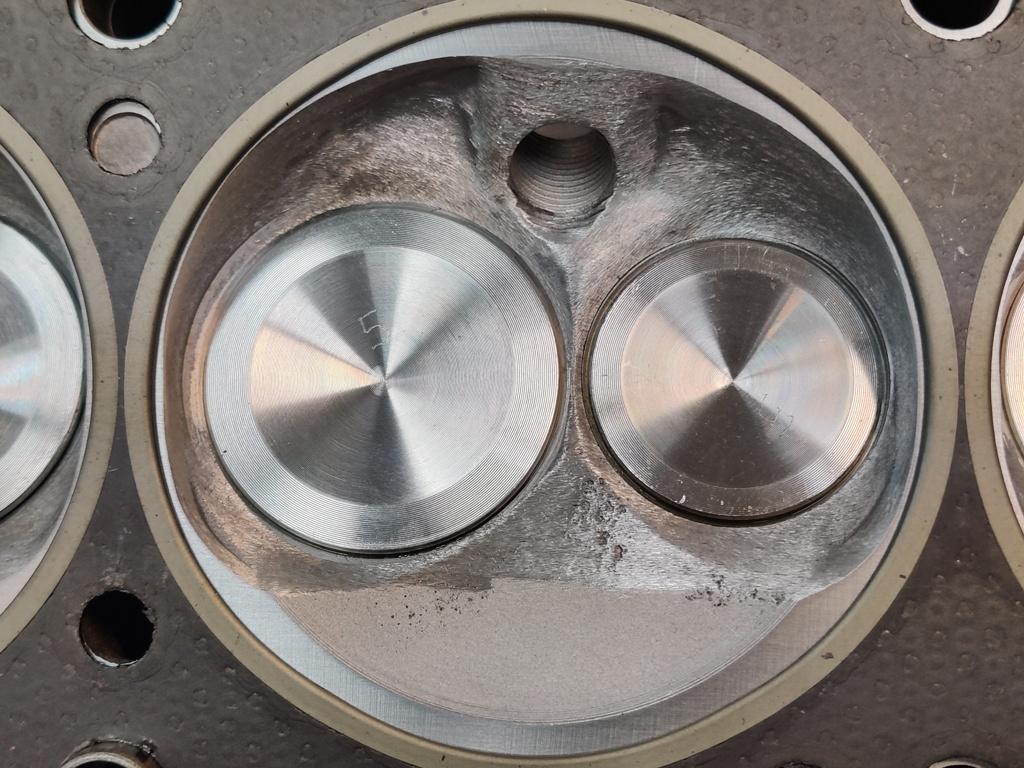
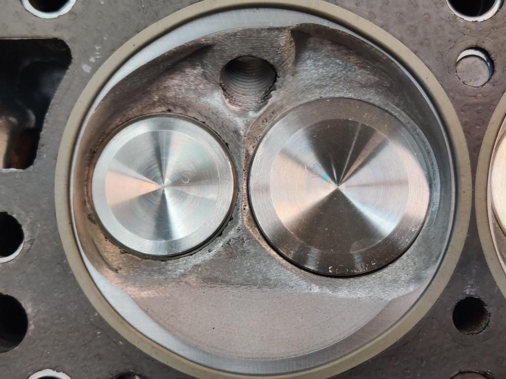
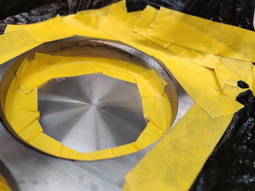
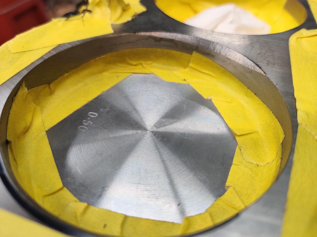
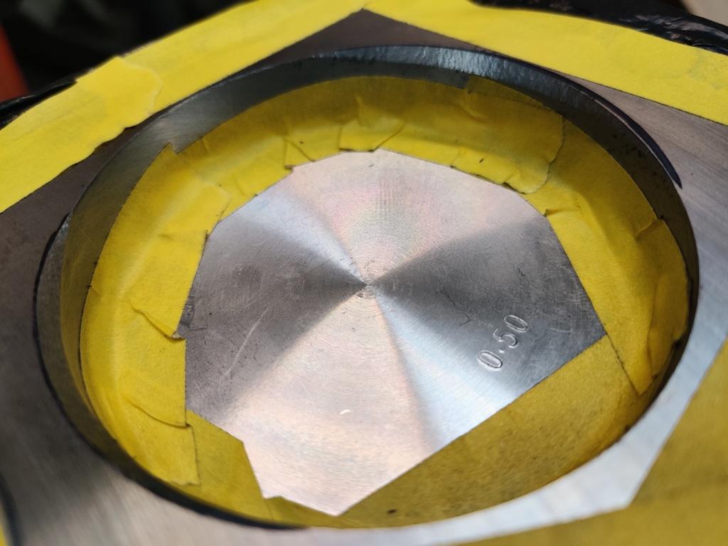
I am getting close to satisfied with the block eye brow and combustion chamber mods. I have a few areas I see in the pics that need attention. I actually can see them better in the pics because I can zoom in on them and compare from one cylinder to another. So this is helpful to document them in this way. Cylinder 1-3 and 4-6: Cyl. 1 exhaust (front of bore - also note ring location by rust stain), Cyl. 2 exhaust (back of bore), Cyl. 3 exhaust (back of bore): Cyl. 4 exhaust (front of bore), Cyl. 5 exhaust (front of bore), Cyl. 6 exhaust (back of bore: Cyl. 1 intake (back of bore - also note ring location by rust stain), Cyl. 2 intake (front of bore), Cyl. 3 intake (front of bore): Cyl. 4 intake (back of bore), Cyl. 5 intake (back of bore), Cyl. 6 intake (front of bore): I think I have those all labeled correctly. Of course, I also still need to assemble everything in mock fashion to check clearances.


-
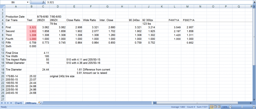
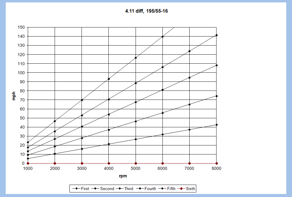
I created a spreadsheet many years ago that is nice for exploring transmission options. Here are a couple of screenshots: In the rows below the screenshot above, I have the speeds in gears return in formulas for each 1000 rpm This sheet is nice because it accurately (I think) takes into consideration the tire size as well as the rear ratio and the gears. You only change a few parameters... and, it allows you to plot speeds in gears and look at a graphical representation: I used it recently to investigate using a 240SX transmission. If you want to use it, I can upload it somewhere for you. Let me know.
-
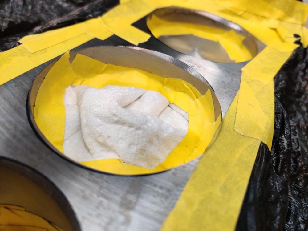
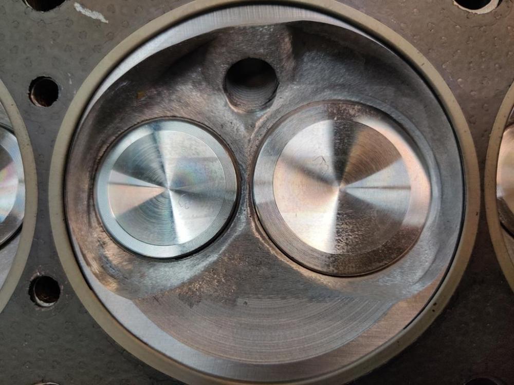
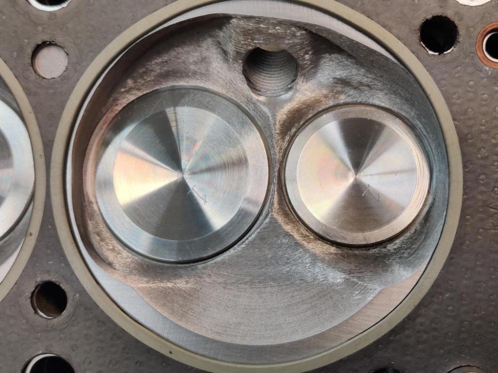
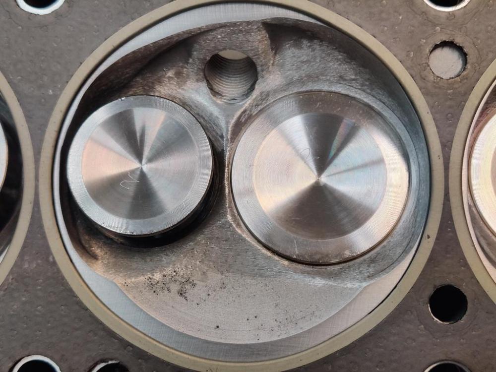
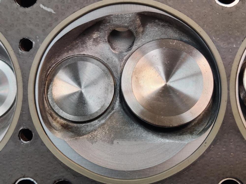
Chambers 1 to 6 in order from left to right after very little ground away, only nearest the valve and to the fire ring: I put the entire head inside a plastic bag and taped off everything so I didn't get any grinding dust anywhere in the head or valves, etc. I will check valve to block clearances next. Before the head goes back on for good, I will address any sharp edges that remain.


-
Thanks for your comments! Yeah, is hard to explain. Basically, if you look at each of the pics of chambers 1 through 6, and look at the 3 o'clock and 9 o'clock positions specifically for each, only chambers 1 and 2 have edges that match up with the fire rings... and further, for the #1 chamber, it is only the exhaust valve side that matches up (3 o'clock position in the pic), and for the #2 chamber, only the intake valve side matches up (also the 3 o'clock position in the pic). All of the other combustion chamber edges (at 9 o'clock for all chambers, and at 3 o'clock for chambers 3 through 6) are not yet cut as far as the edge of the fire ring. So, I am saying it seems like I need to open the chambers at those positions for each chamber so that they all align with the edge of the fire rings in the gasket. Understood. I have to provide clearance for the valves, so trying to do that, and I am assuming that breathing benefits that come from what I have outlined will be worth more than compression lost from the mods. I have no idea though - so if there is an expert who chimes in, that will be great! Yep, it is oval. It is wider at 3 and 9. And I'm not touching anything at 6 and 12... or 5 and 11, or 7 and 1 for that matter. I probably went a bit far north and south with the eye brows I already cut in the block at the 3 and 9 positions. The rest of my mods to the block will be more central to the 3 and 9 positions, generally. Agreed. And yes, the gasket has been compressed once. But I will leave a small amount of material there so I am not precisely at the fire ring with the edges of the chamber. The two edges mentioned above that are already matching up are REALLY close.
-
Thanks. I appreciate the positive reinforcement! I have been studying it and the cylinder head for a few minutes each of the past couple of days. I want my next steps to be right ones. Checking the gasket against work that has been done so far on the head (valves are marked with cylinder number): The work already done to open up the breathing on the exhaust for #1 and intake for #2 puts the edge of the combustion chamber at the gasket edge, but only for these two edges: It seems desirable to do further work on the other sides of each of these chambers to align the chamber edge to the fire ring also... and to do the same for the areas where the chamber wall is close to the valve heads in the other chambers as well. That said, the tops of the bores are not as wide as the chambers in the matching areas, even after eye-browing. So, the question is should I open them outwards to match? And, should this be done for both the intake and exhaust valve sides of the cylinders (safely above the number 1 piston rings of course)?


-
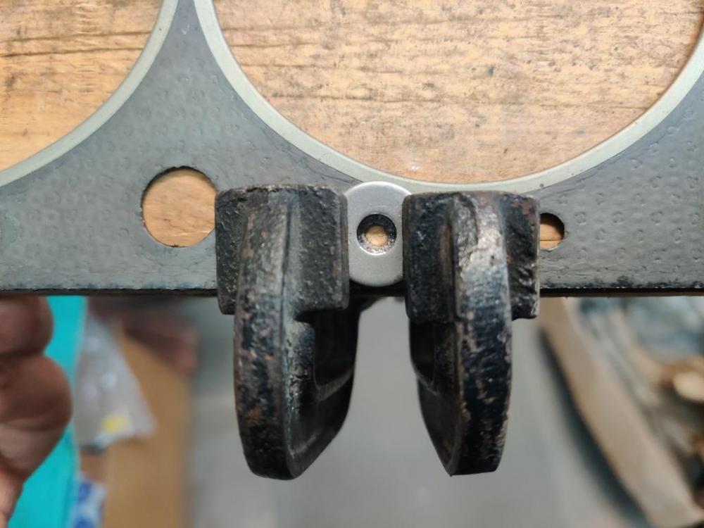
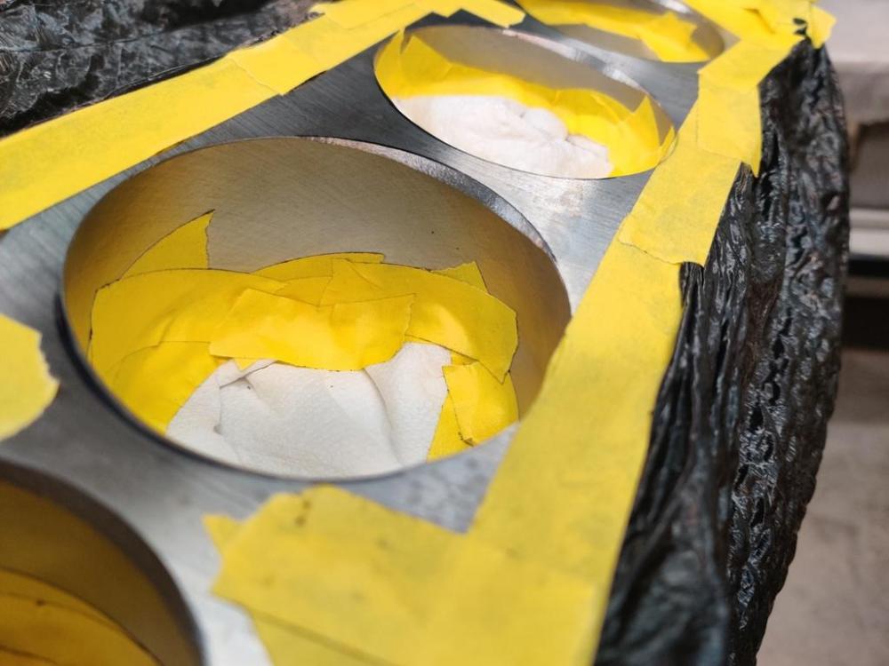
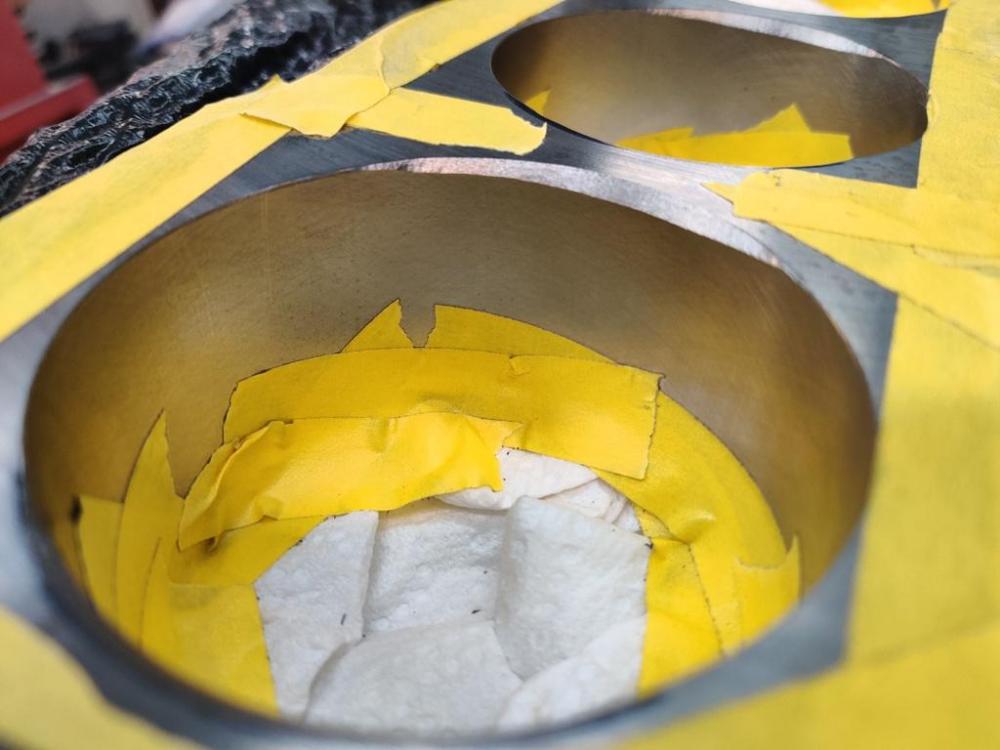
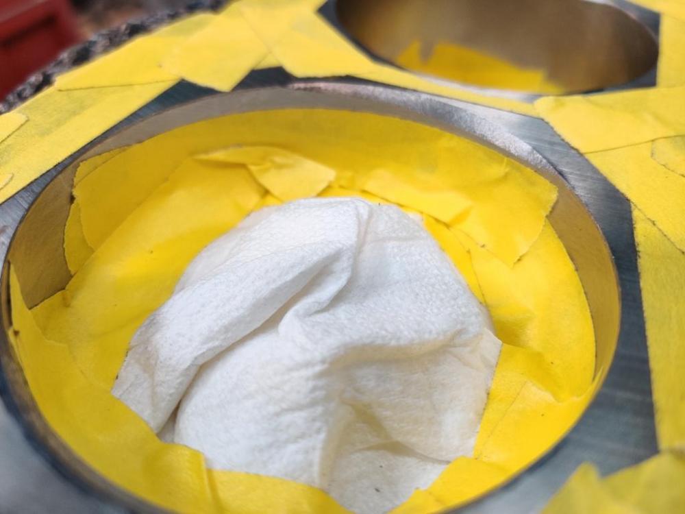
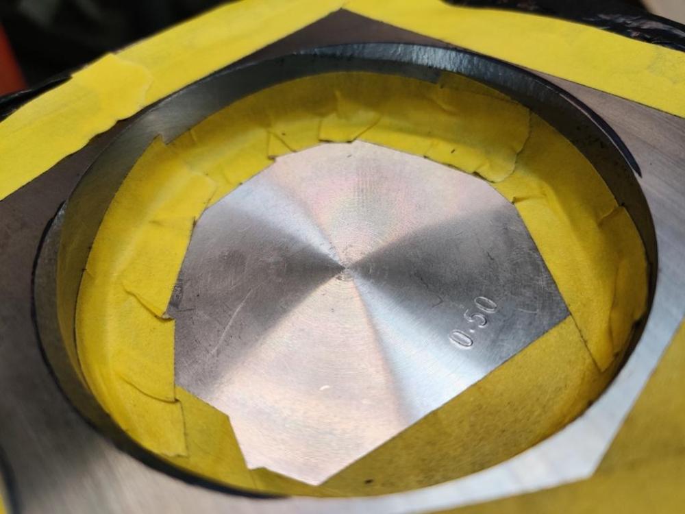
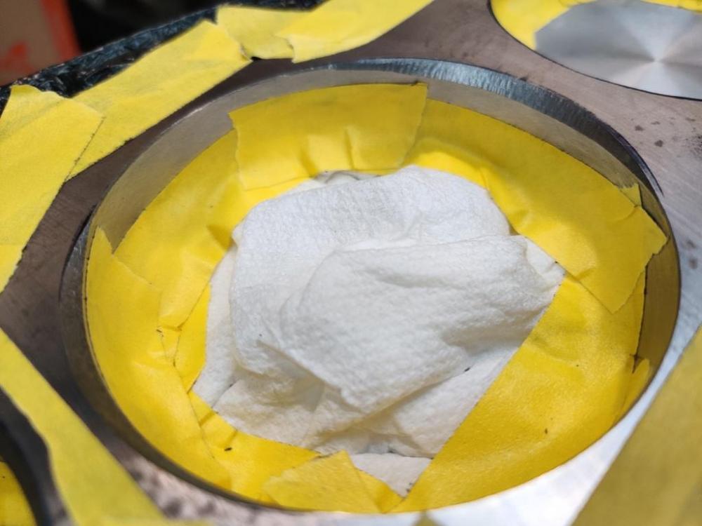
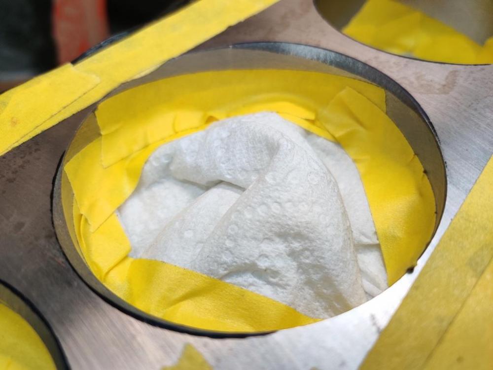
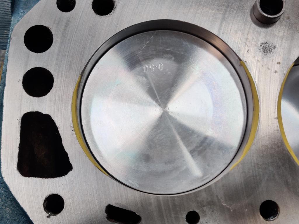
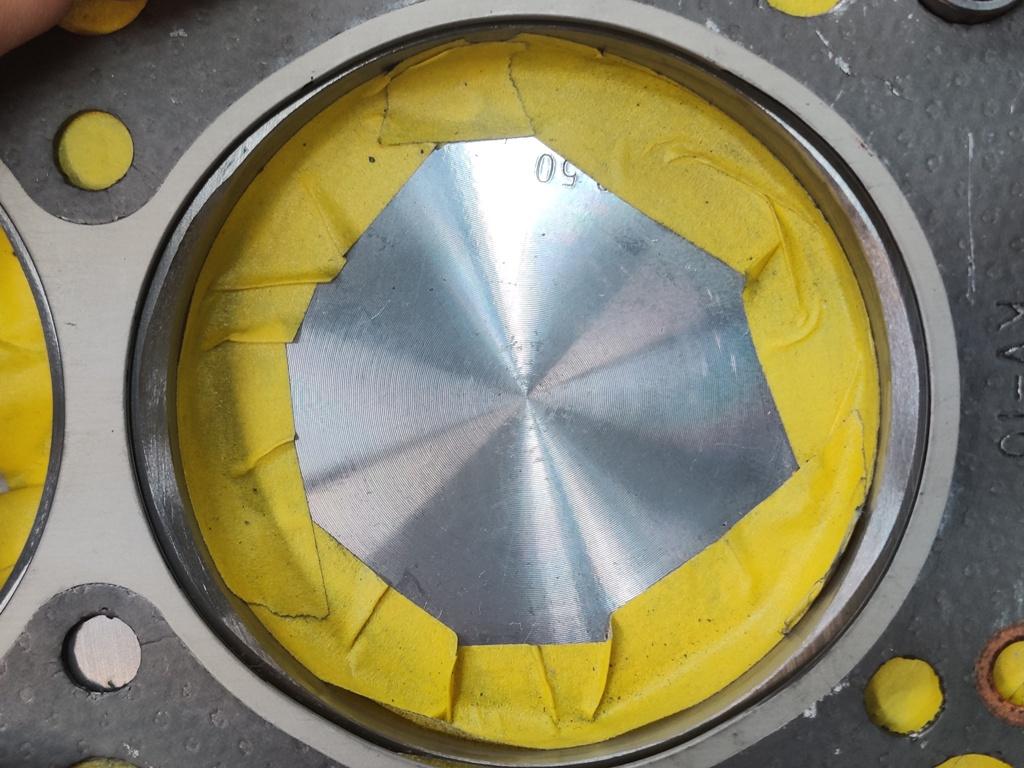
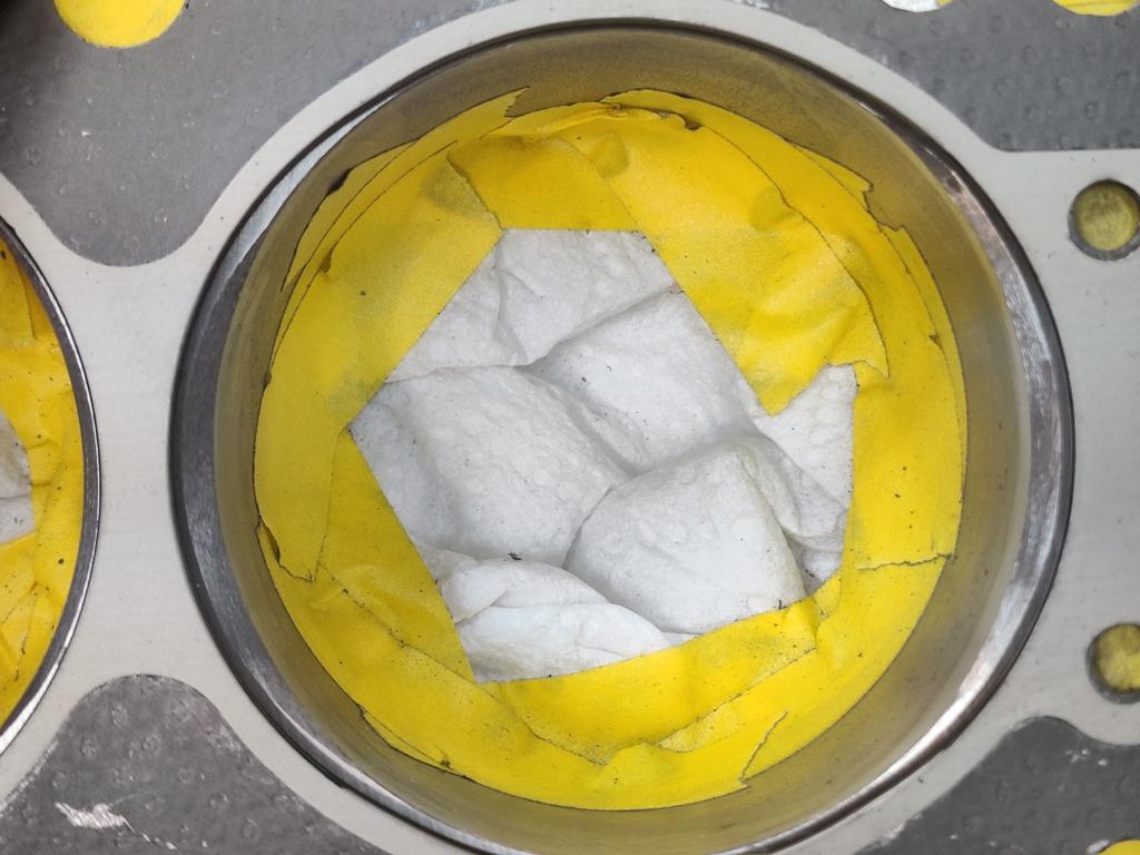
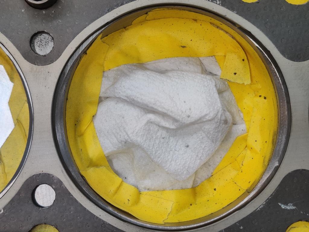
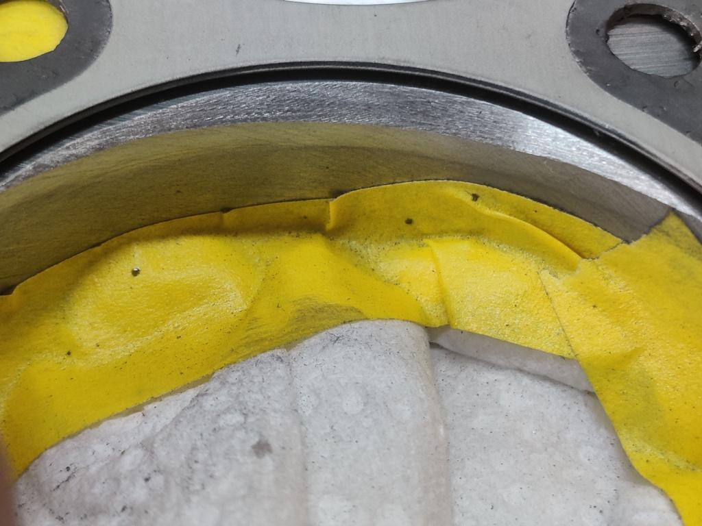
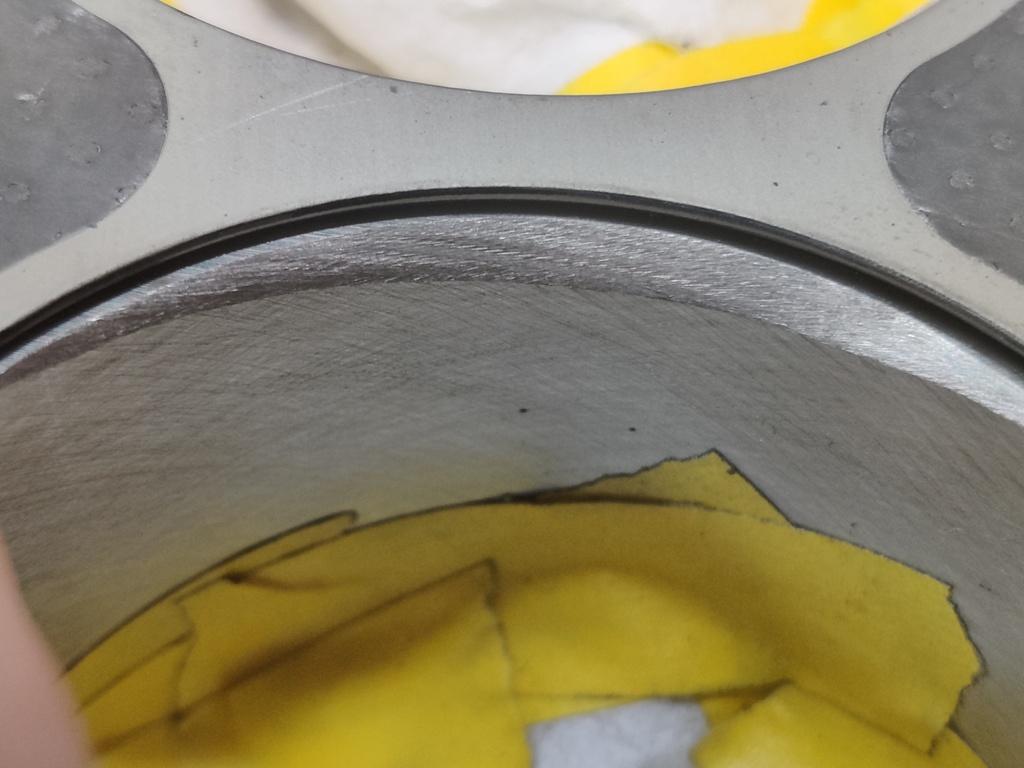
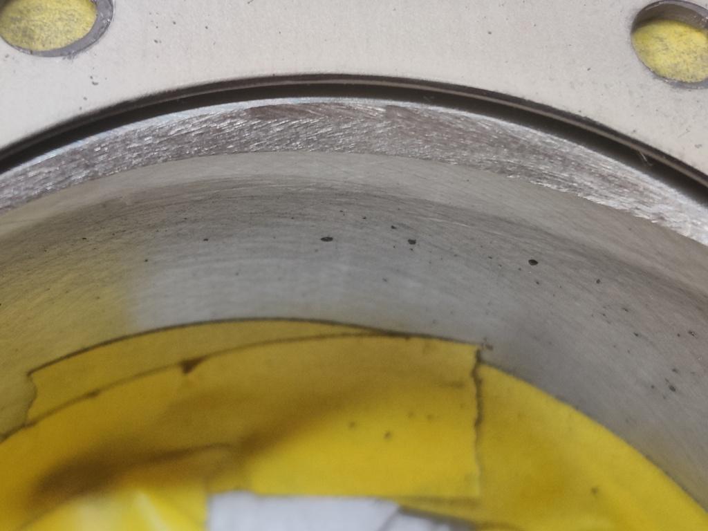
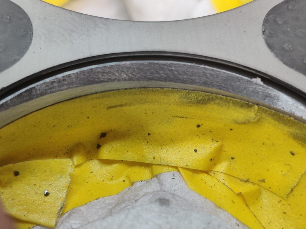
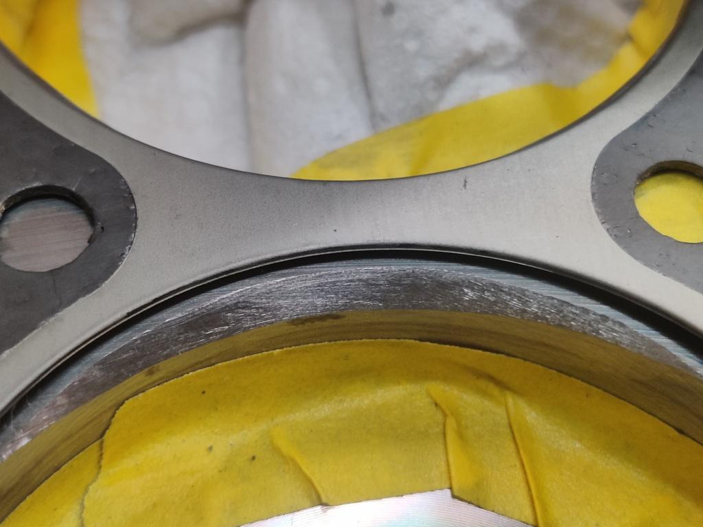
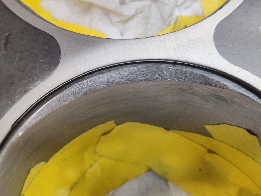
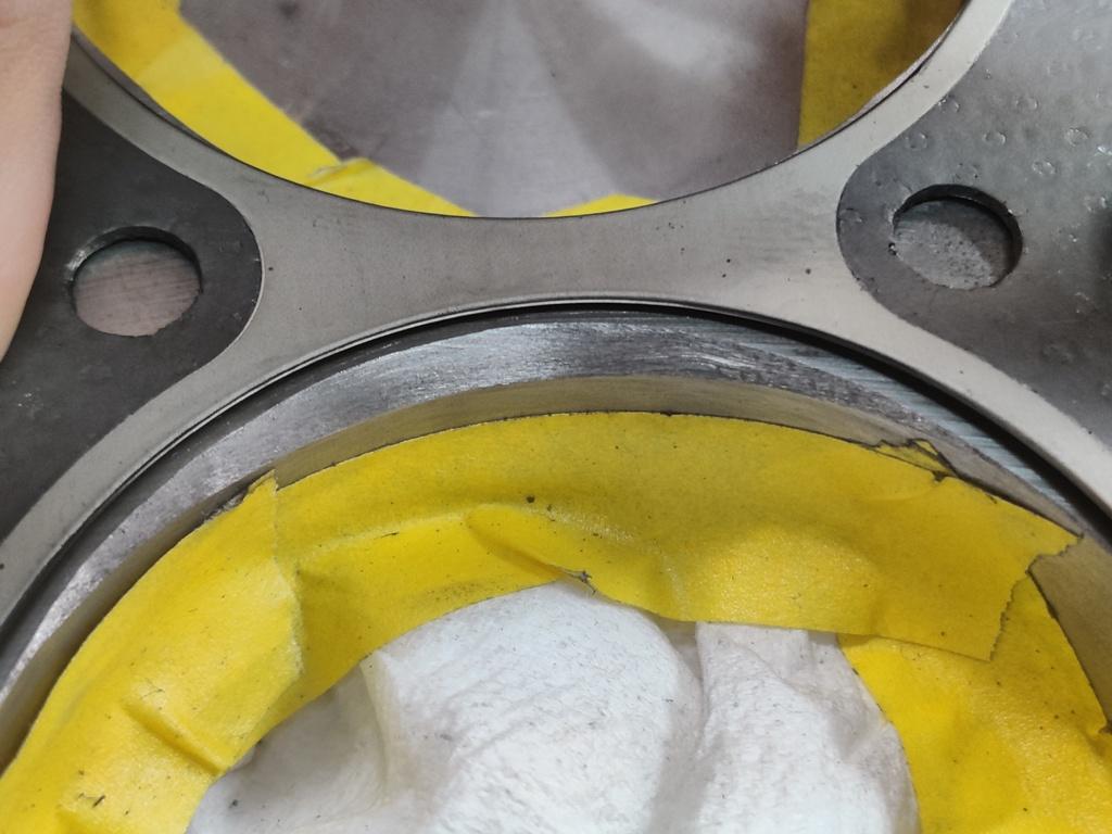
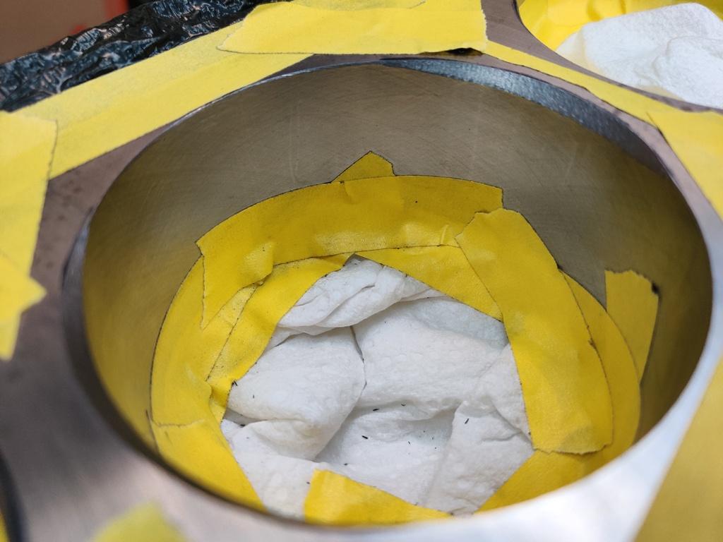
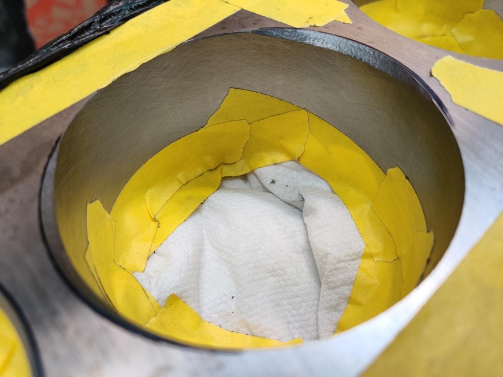
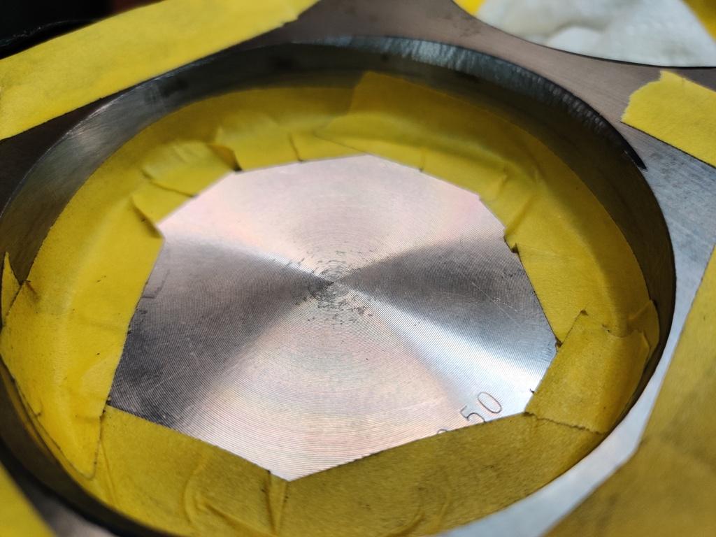
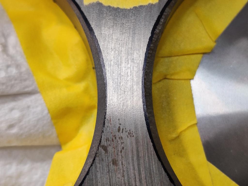
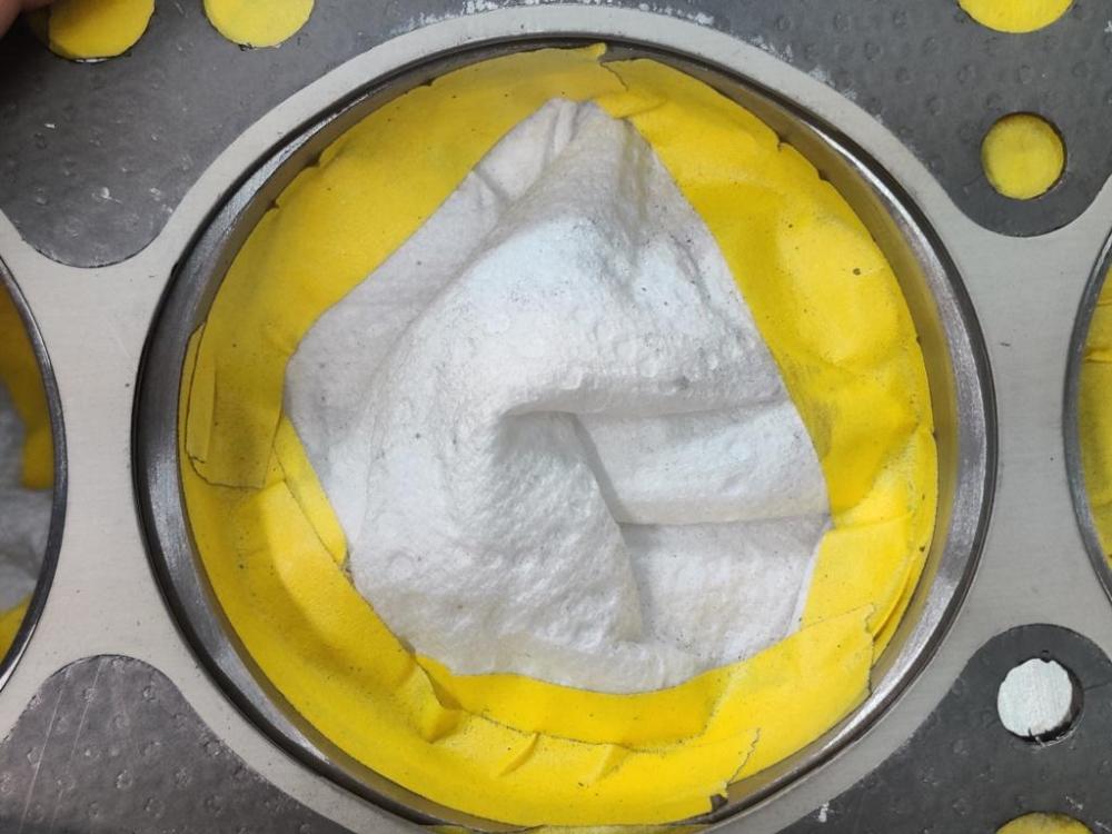
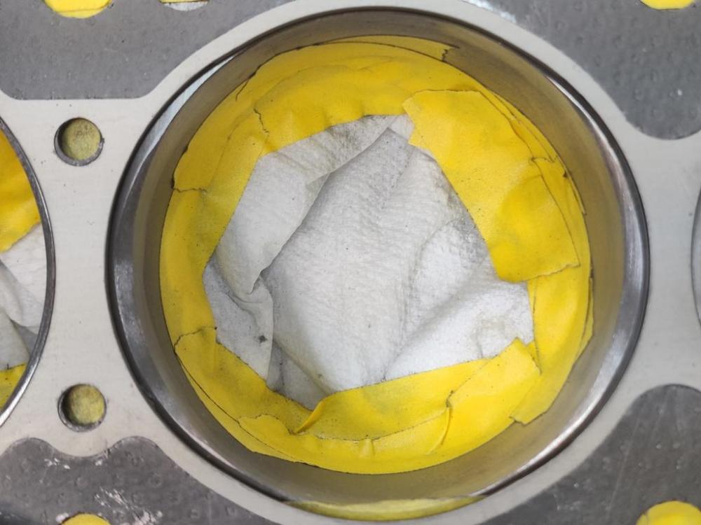
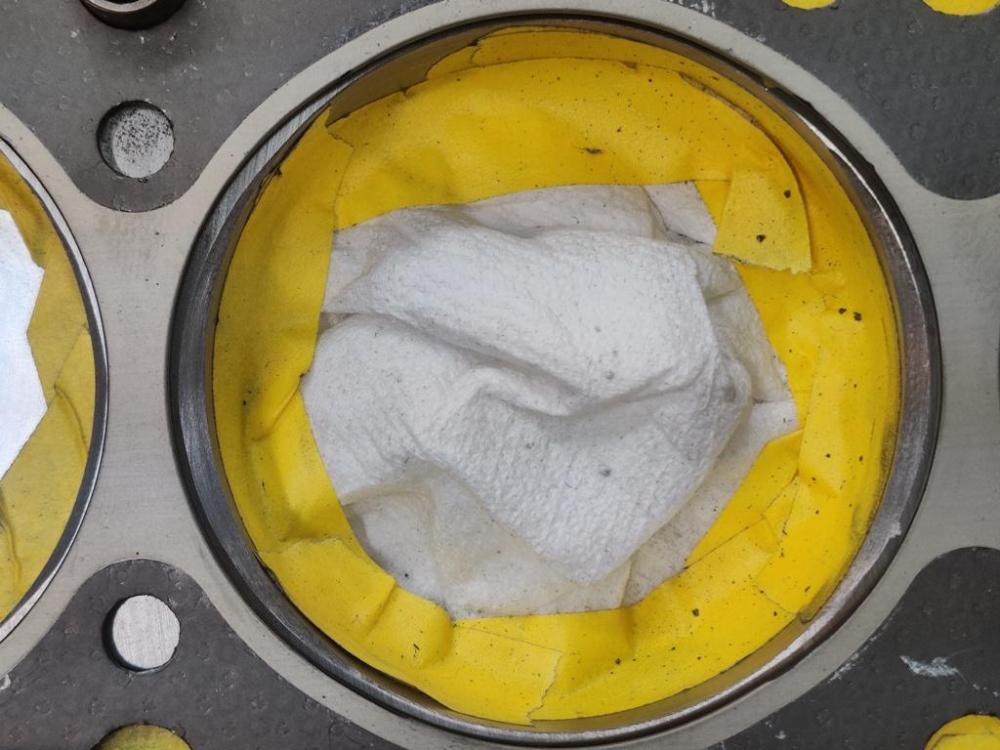
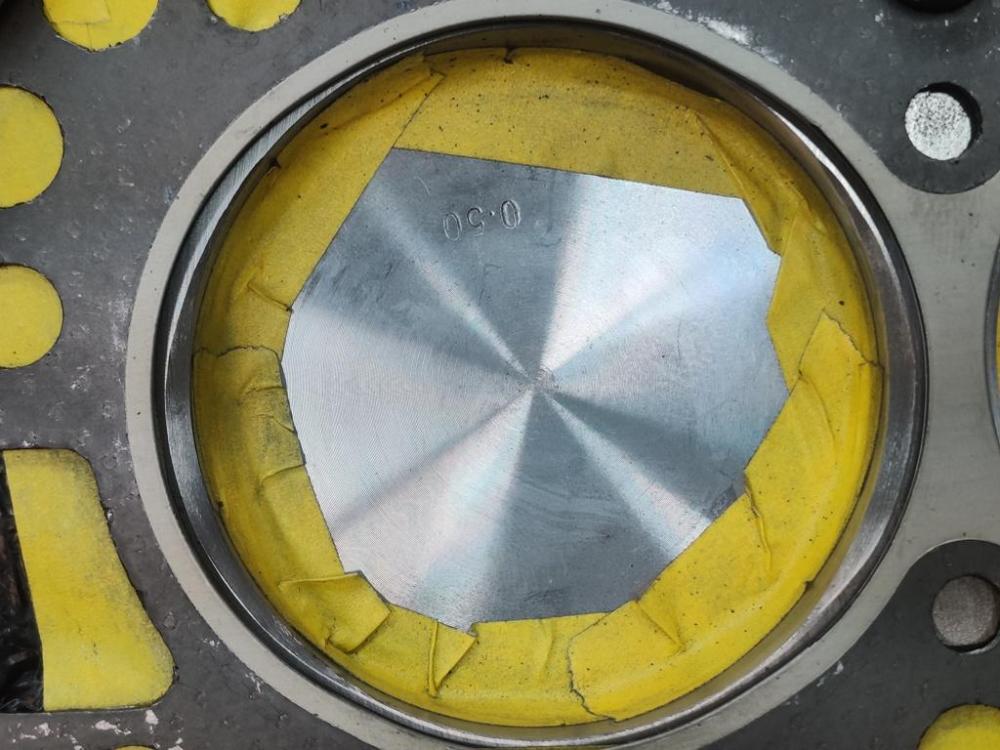
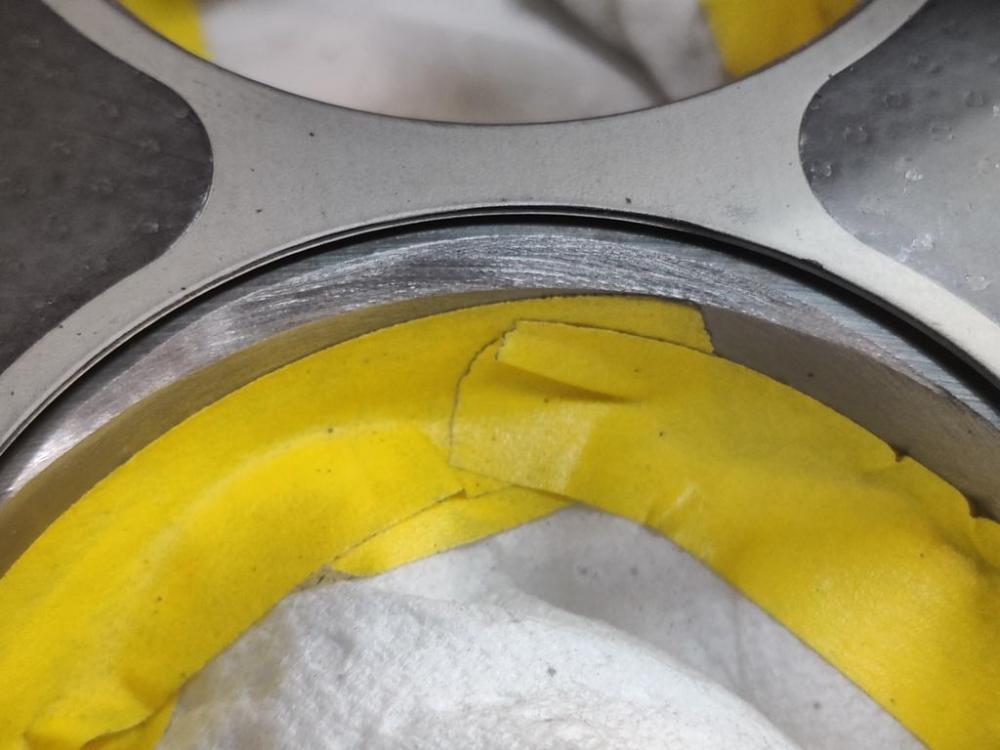
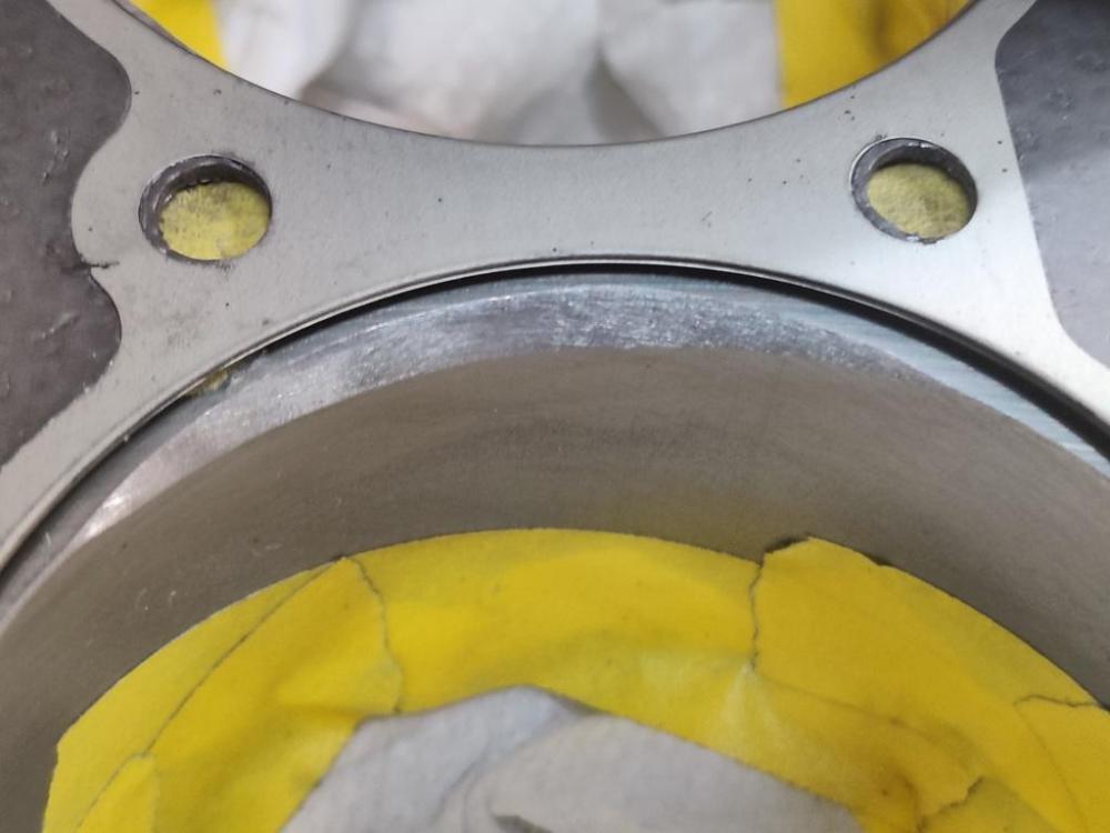
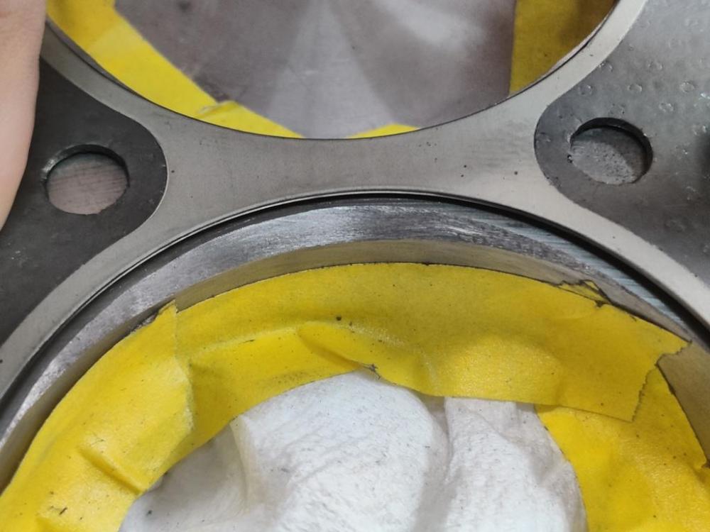
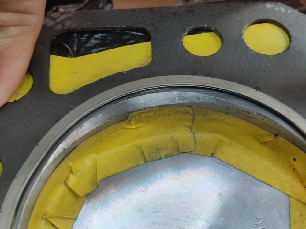
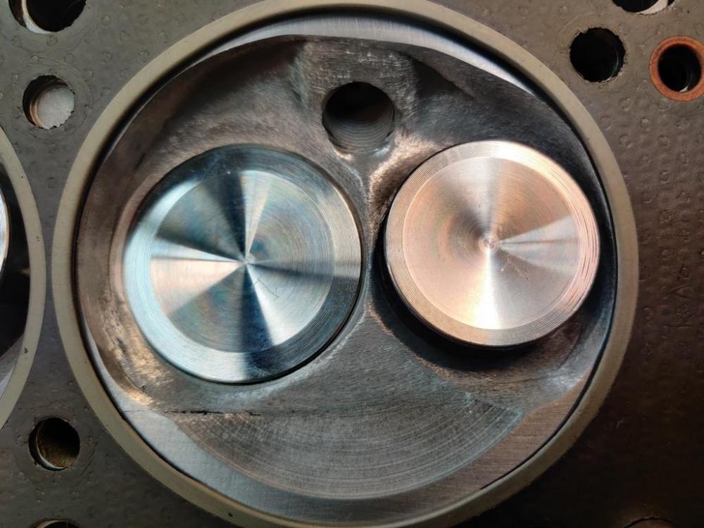
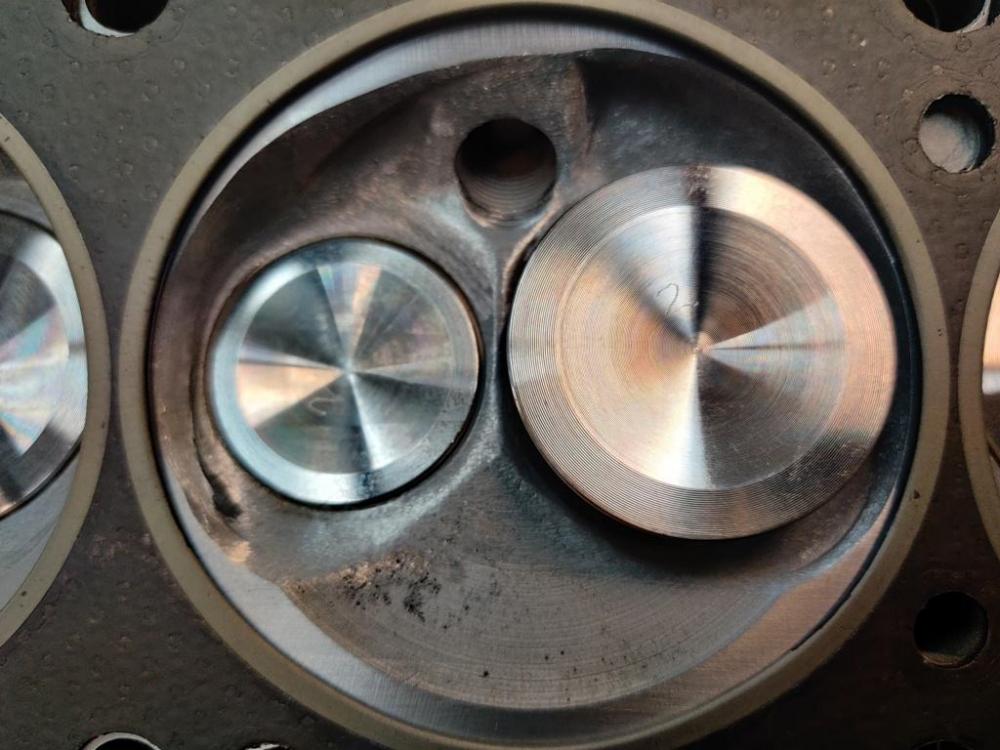
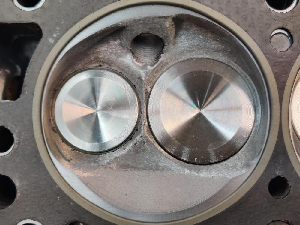
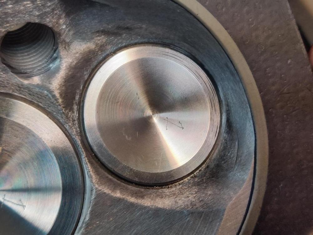
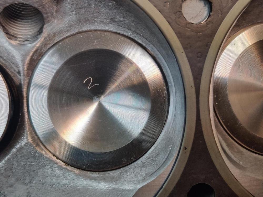
Alright then. I took the head off today. The head gasket didn't stick to the block or the head, so I think it is reusable. After I got the head off, I went to work on modifying the gasket. I used a washer with a 1/4" hole to guide the drill bit. With the gasket modified, I turned my efforts on eye-browing the block. Hopefully, I have not royally screwed up here. I removed the timing chain, rotated the crank to get the pistons below deck, and then covered the block with a plastic bag, and cut out the top of it so I could access the tops of the bores. piston 1 - pic taken from passenger side - front of piston is toward the top of the pic: piston 2 - pic taken from passenger side - front of piston is toward the top of the pic:: piston 3 - pic taken from passenger side - front of piston is toward the top of the pic: piston 4 - pic taken from passenger side - front of piston is toward the top of the pic: piston 5 - pic taken from passenger side - front of piston is toward the top of the pic: piston 6 - pic taken from passenger side - front of piston is toward the top of the pic: piston 1 - pic taken from driver side - back of piston is toward the top of the pic: piston 2 - pic taken from driver side - back of piston is toward the top of the pic: piston 3 - pic taken from driver side - back of piston is toward the top of the pic: piston 4 - pic taken from driver side - back of piston is toward the top of the pic: piston 5 - pic taken from driver side - back of piston is toward the top of the pic: piston 6 - pic taken from driver side - back of piston is toward the top of the pic: A few more pics: I did this with a die grinder and oval cutter. Tape and bag is still in place. I think I will switch over to a tapered roll and try to look for inconsistencies to address... as well as smooth the eye brows to final finish. I am well above the top ring land currently, and inside the fire ring on the head gasket as well. I was being cautious (I hope!). I will check clearances and continue - before I bolt the head on.