inline6
 Subscriber
-
Joined
-
Last visited
Everything posted by inline6
-
 Hi Kats, I know you look at eBay in the US. Are these too expensive? https://www.ebay.com/itm/235682782552?_nkw=datsun+240z+brake+master+cylinder+cap&itmmeta=01J67QJ9PY0AS770M2QXW1T476&hash=item36dfc9dd58:g:K2MAAOSwjqNgPFM8&itmprp=enc%3AAQAJAAABAHoV3kP08IDx%2BKZ9MfhVJKkgEI8xlrOrXR35ZVEauWhWy3b8zqM5sCMdsPS%2B6W3J1gShEGzW56wS9%2BnAJ57eSUYPiXhT2D6XTQLZmKj9x85i31Kt6IooZKn4Sx3mT5vUNWaVGsIRnMyhcxGwYZJ2Hgnww%2FiWahettnb9CA7%2BQHysIe6DnRn683anTugQjDTwOkVbycEemnRtOZKwFIDGcZAAI09Gc%2B9EnVkTT9OZras%2BdFMv04JujhXmtUyosCFGeZI68fy62idnDVpZbRC2KqRdOH%2FDSaNqZ1--0AQZ%2B4PuGZJOCidpcoNO3tRNpvtPXV%2BUW0Td8LqreQYYFC2GITM%3D|tkp%3ABk9SR8ibyfexZA
 -
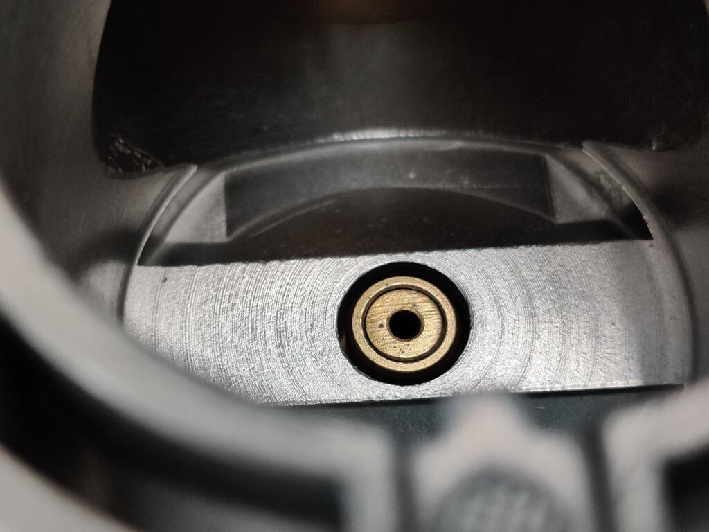
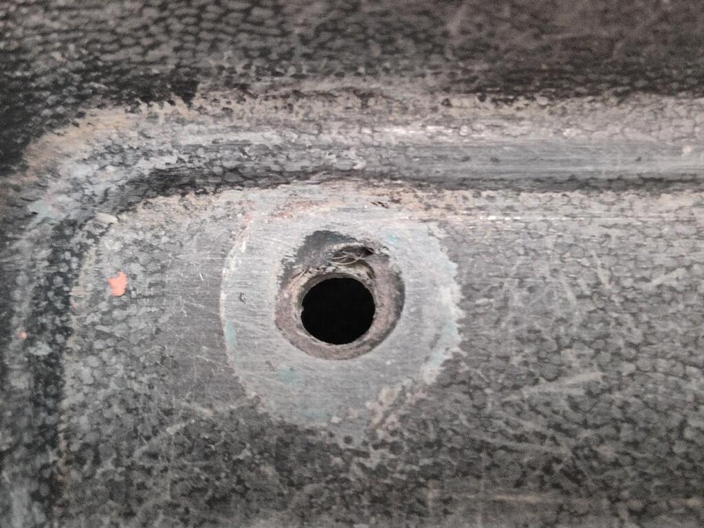
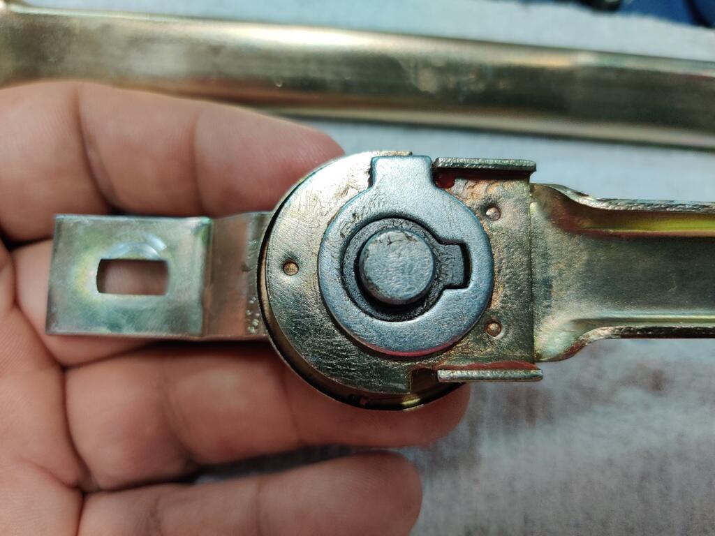
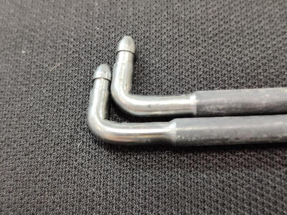
Working on the car today was not fun. I put in about 8 hours. First problem I ran into was the SU nozzle issue above. When compared the nozzles side by side, interestingly, the shorter of the two had not actually been shortened. The nozzles have a little groove around the circumference. You can see it in the picture below. Aligning the grooves on the nozzles, the distance from the groove to the top of the nozzle was the same for each. I decided that the nozzle was going to have to be replaced. But, I couldn't set it aside. I had to mess with it. So, I ended up removing this crimp collar (using a hammer and flat punch, it came off pretty easily. After that came off, I was able to remove the brass nozzle portion from the plastic portion. From there, I experimented with putting the brass nozzle piece back into the plastic, but not as far in. And then I pressed the collar back in to place. It took me 3 tries (remove the collar, adjust the height of the brass portion, reinstall the collar) before I got the 'short' nozzle to be the same length as the other one. It seems to be held in place very well when the collar is put into place. However, I don't trust it. My guess is that with heat and use, it may "drop" down further into the plastic portion of the nozzle. So, ultimately I wasted a bunch of time messing with it - time I really should have spent making progress on the car to try to get it ready for Z-Con. From there I worked on the rear hatch glass stainless steel trim. I removed more small dents and stepped my way through 320/400/600/1000/1500/2000/2500 grit sand papers and then used metal polish on them. Each one took a lot of work. Then, I TRIED to install them. I had no idea it was going to be so hard. Literally impossible with all my expertise and tools on hand. I ended up cutting/slicing/gouging the rubber hatch glass gasket in so many places that it is trash. I am so frustrated. I really thought that it wouldn't be that difficult. So, now what? I have to remove the rear hatch glass and replace the seal. While it is out, I can try to put the trim in place and then reinstall the rear glass. But what about the front windshield. I don't want to destroy that seal... and I don't want to take the winshield out. What am I going to do? How am I going to get the new stainless trim I bought from Japan installed on that one? Combining the events of today along with the fact that the parts I sent to be plated are not going to be plated in time and my seat belts and small parts sent off for re-chroming aren't going to make it back in time, I'm not going to be able to make it to ZCon. The business I sent a few remaining items to be plated has closed. My package was stuck for 7 days in limbo, but thankfully, I got someone at USPS eventually, and I am having them send my package back to me. So, at least I didn't lose the parts.
-
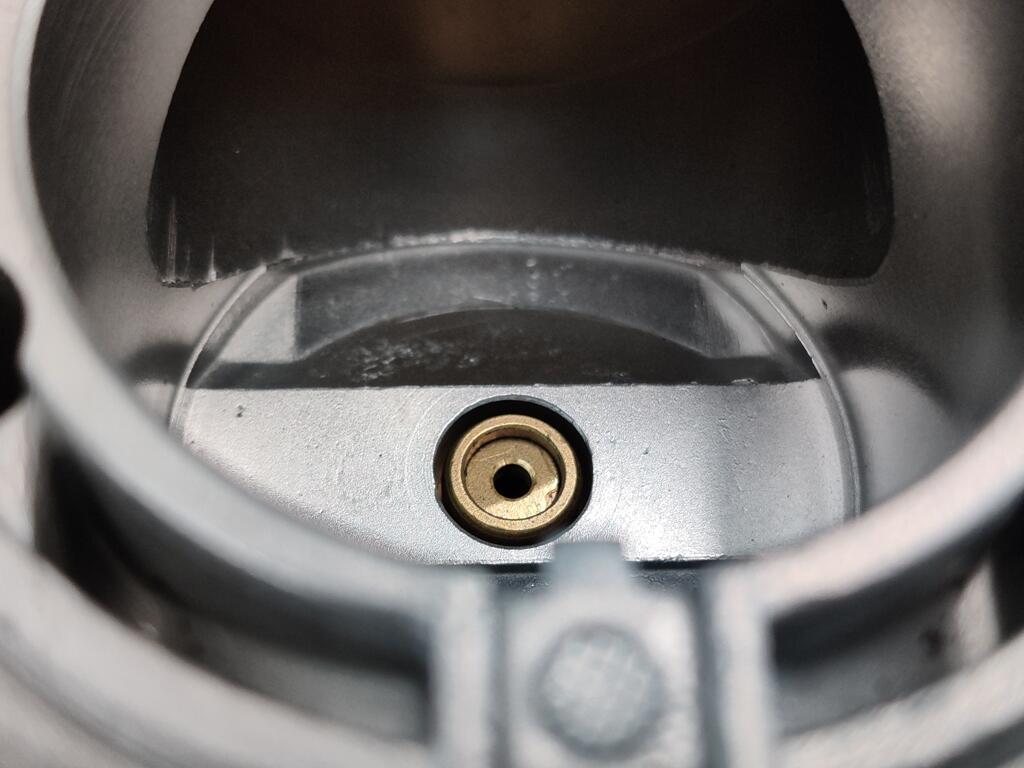
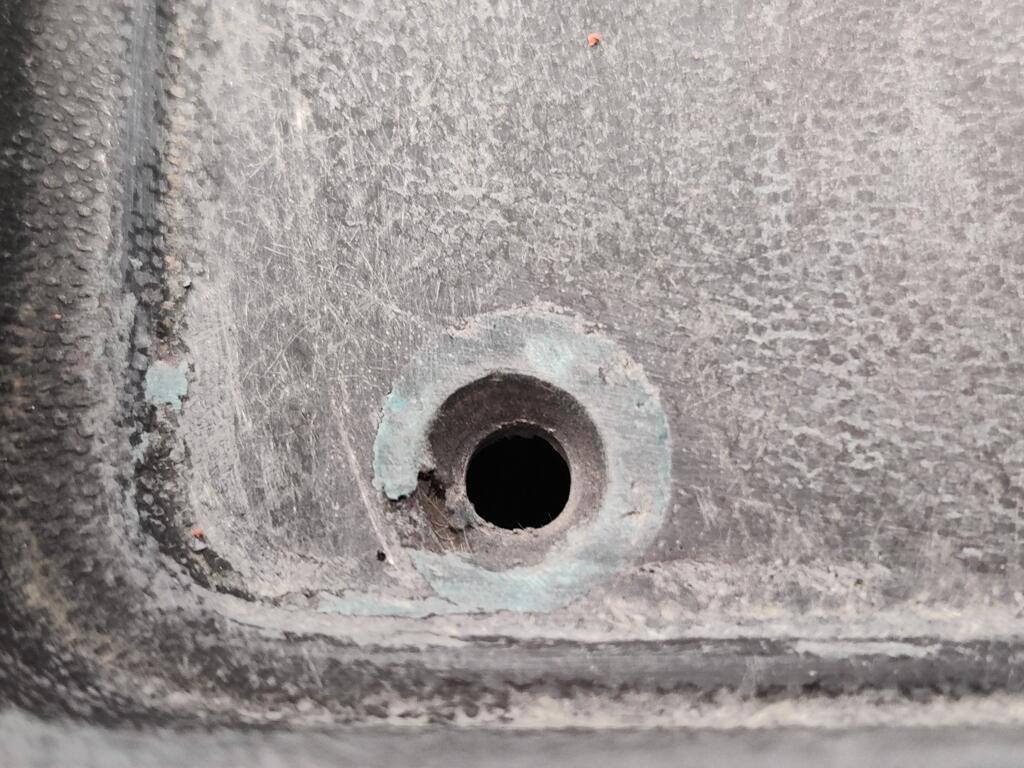
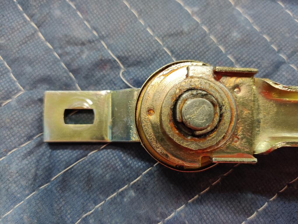
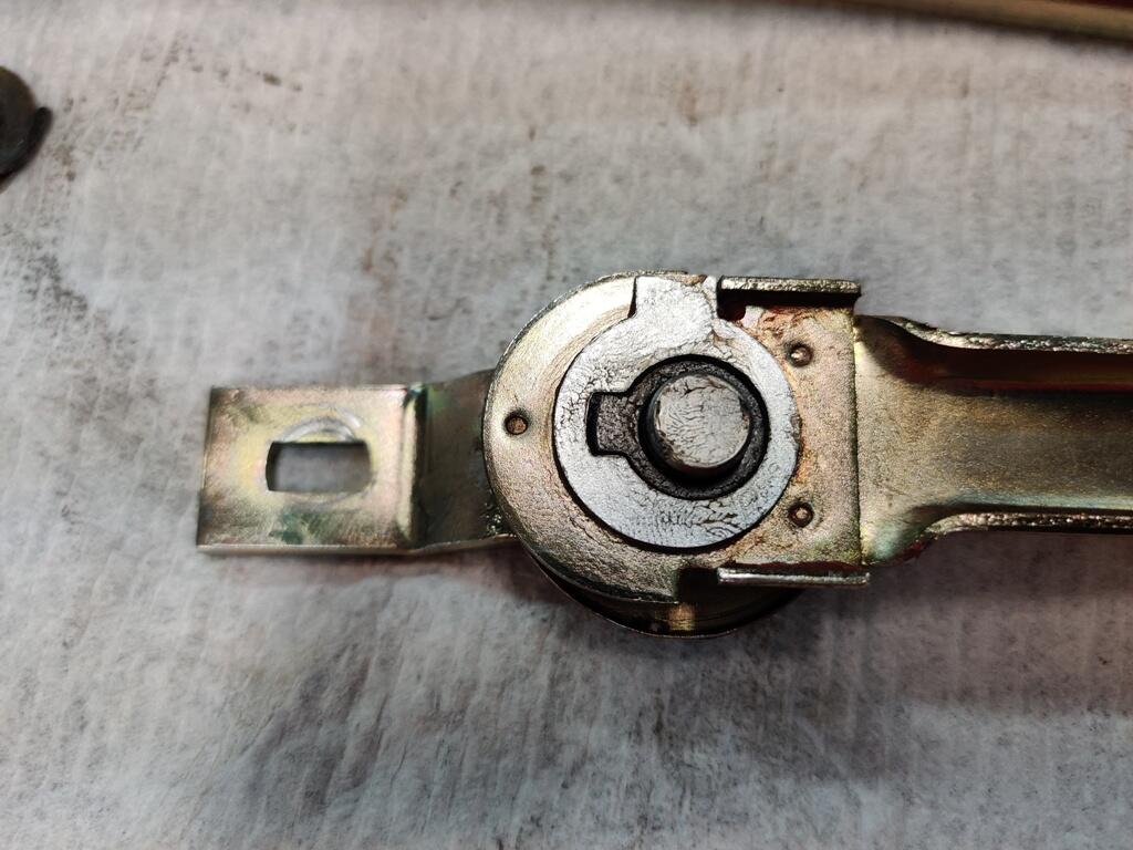
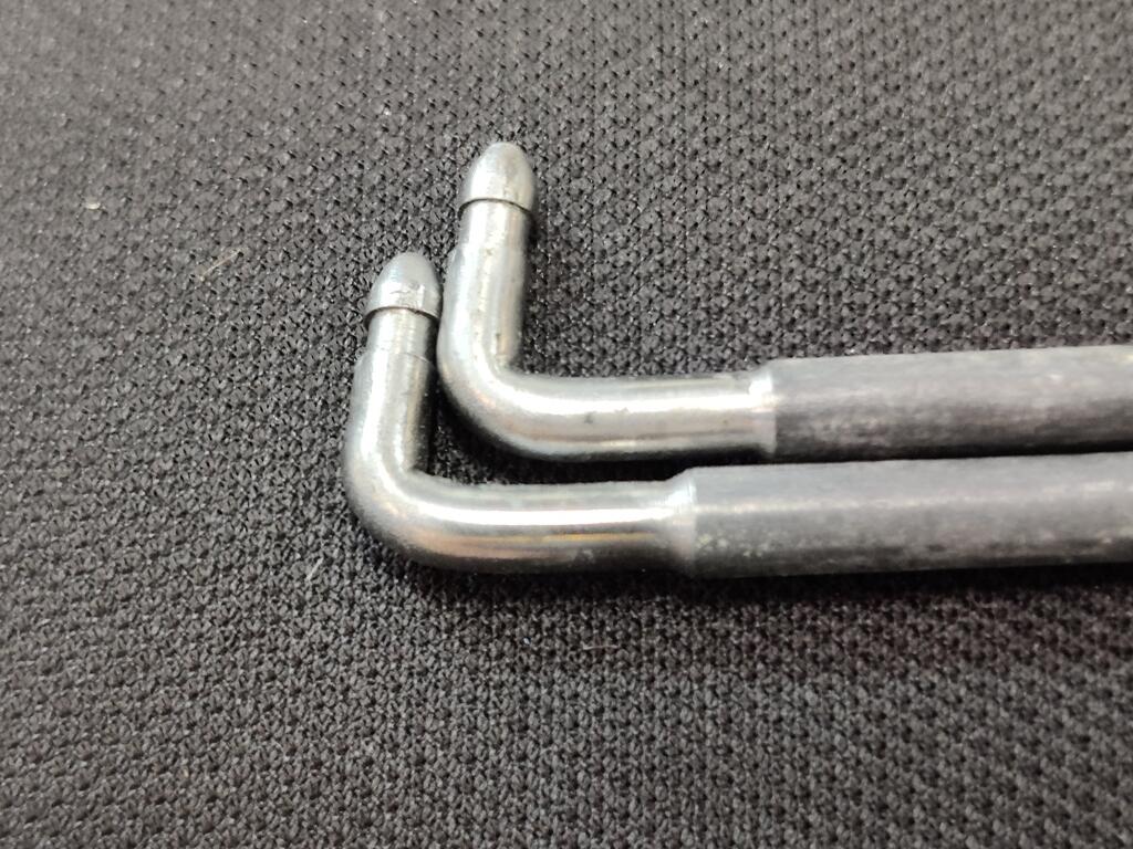
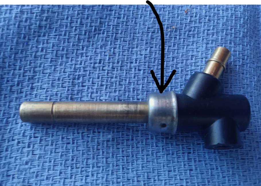
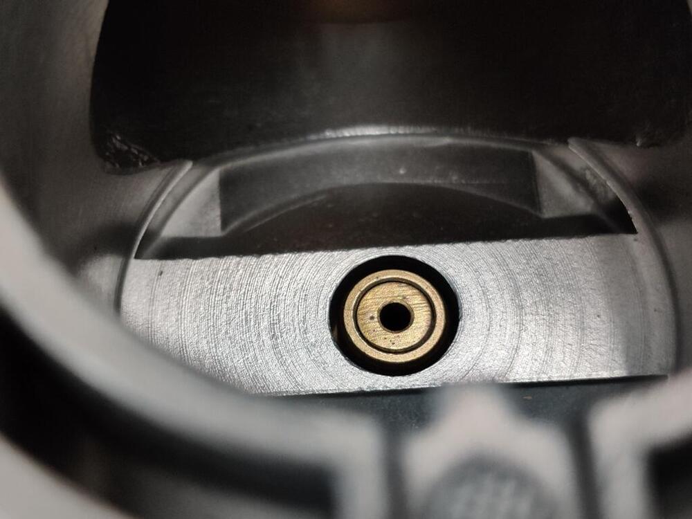
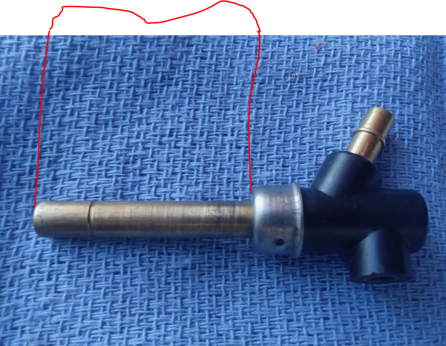
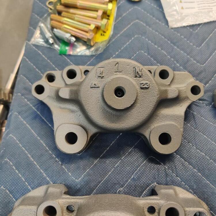
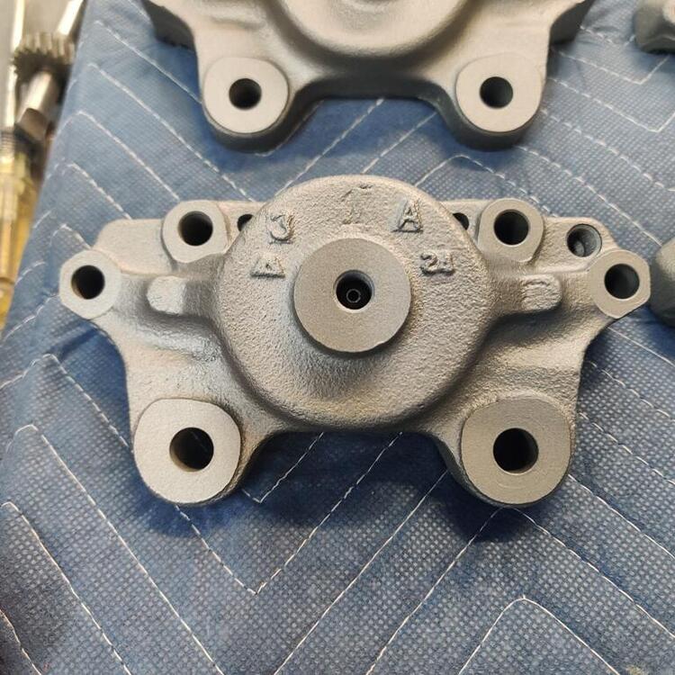
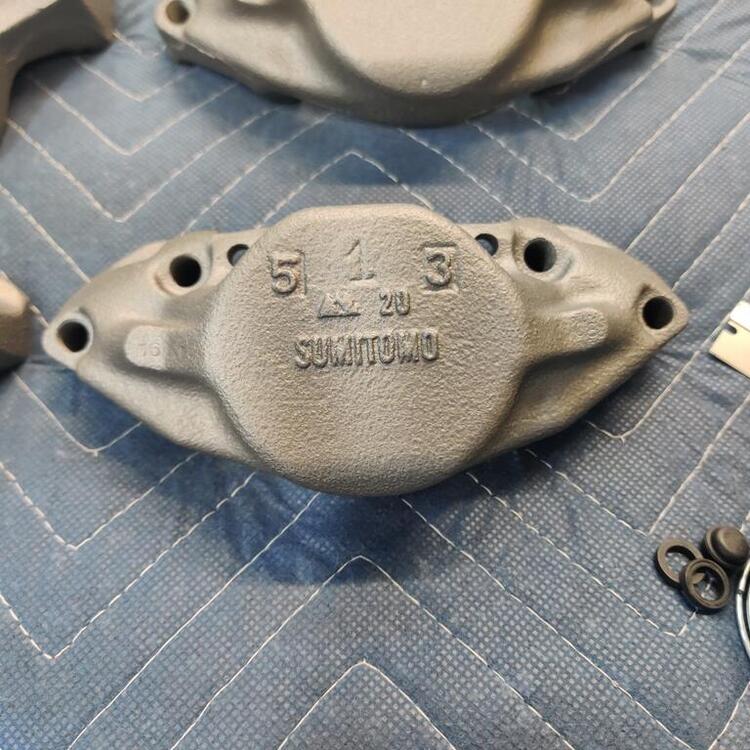
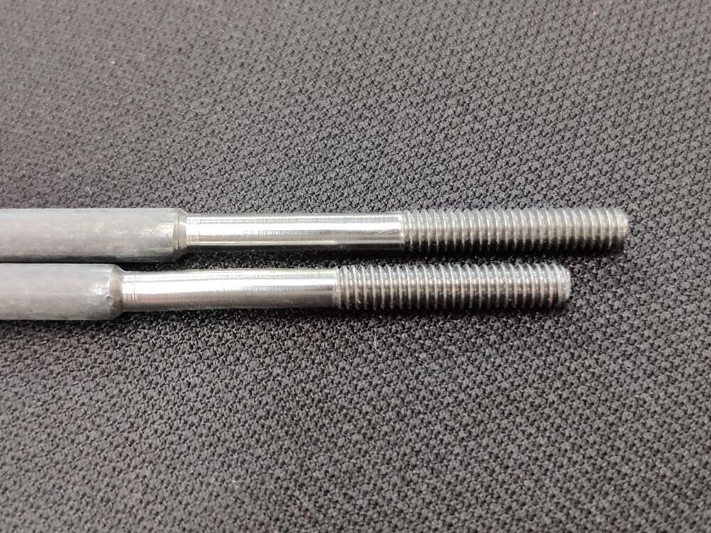
Started to check everything on the carburetors today. They were rebuilt by Paltech - I think they are out of business now. And one of the things on my list to do is to check the basics before attempting to fire the car up. Unfortunately, I ran into and issue. I screwed the mixture screws all the way in on both carbs: Front carb - and back carb respectively: The top of the nozzle on the front carb looks odd. It has a slight angle/chamfer that you can see in the pic. But more importantly, with the mixture screw all the way screwed in, the top of the jet nozzle is not flush with the "surround" - whatever that piece is called. That is not good. I removed the jet nozzles and measured their lengths - this length. The measurements are front: 1.405" and back 1.445". These are 4 screw SU's. Can some folks measure the lengths of any nozzles so I can compare with what I have? I am going to take a closer look at my nozzles. But, I fear someone ground the end of the front one down or something.

-
Yes, @Captain Obvious Date on the door tag for my car is 6/71. Here are mine:

-
Thanks for all the replies! I sprung for this set: https://www.jauce.com/auction/b1143807861 A complete OEM set - that is $289 plus shipping I also found this little gem: https://www.jauce.com/auction/d1147578027 That was $34 plus shipping. Now, how to get them here from Japan in 2 weeks!
-
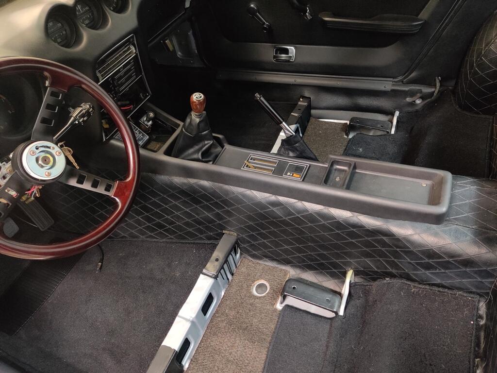
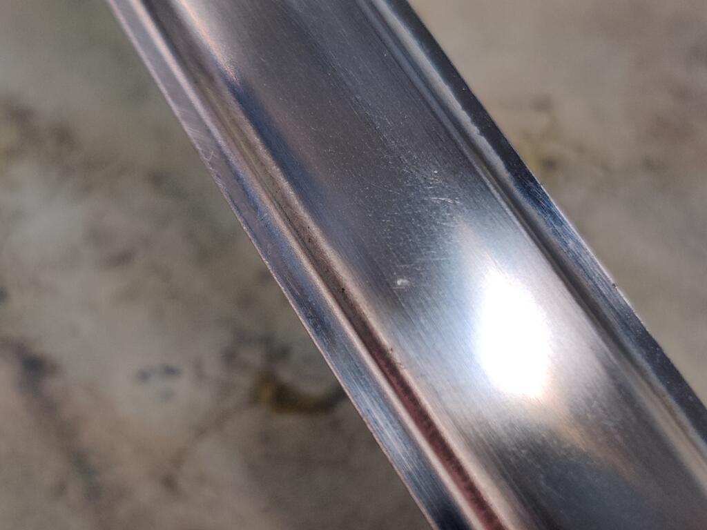
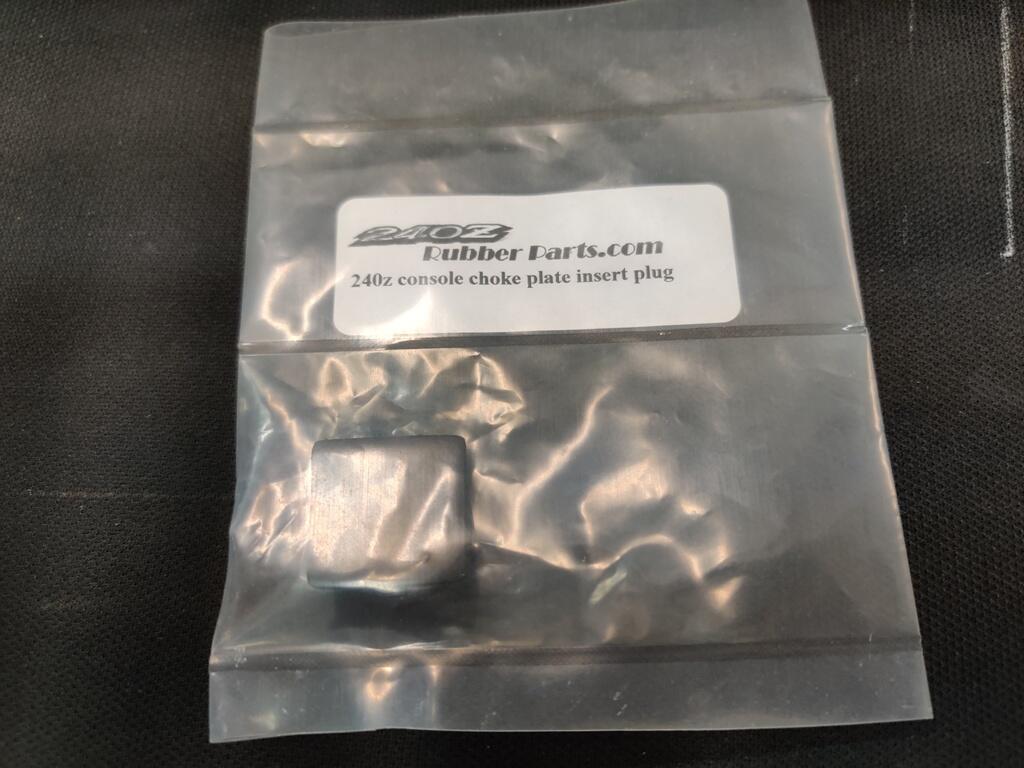
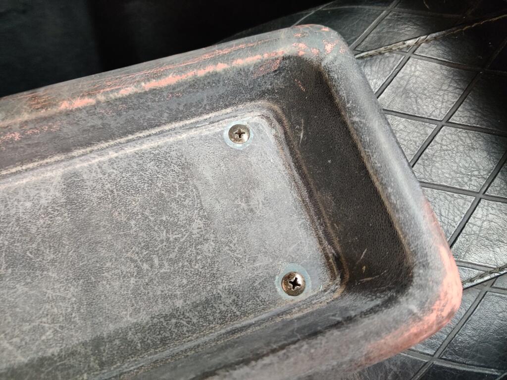
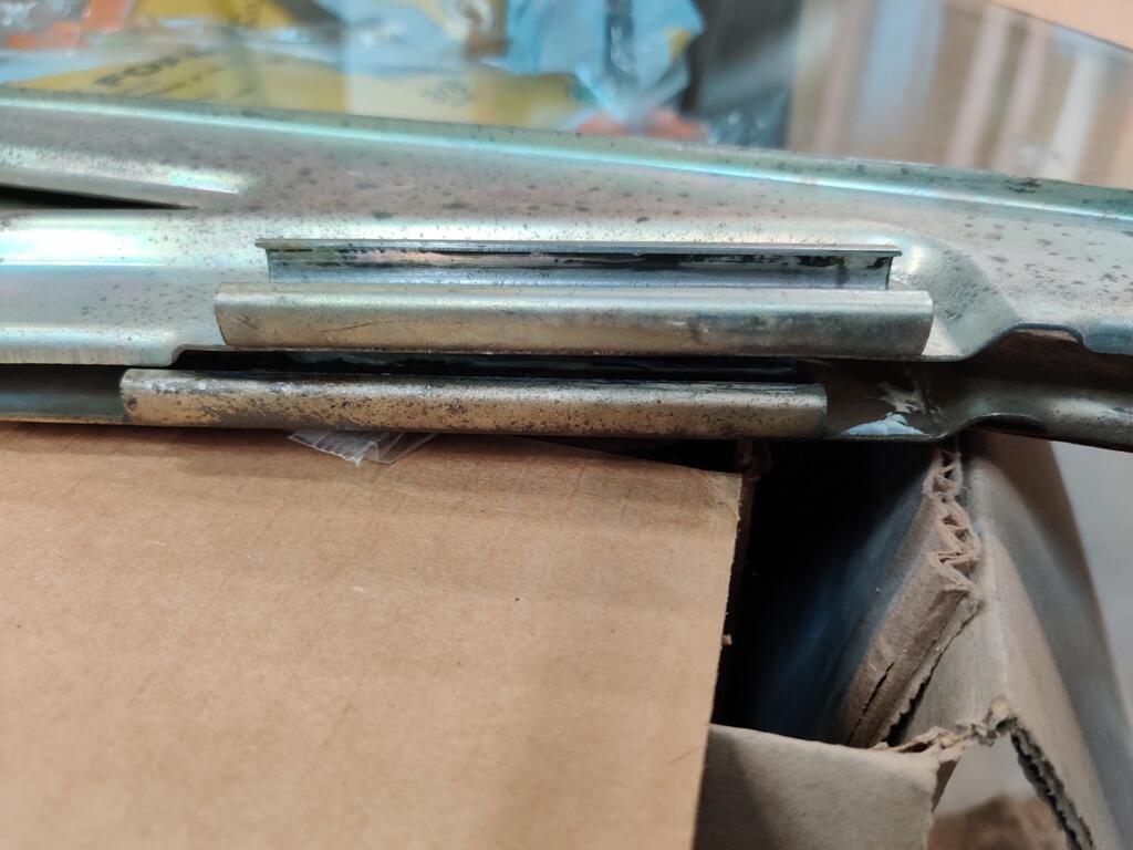
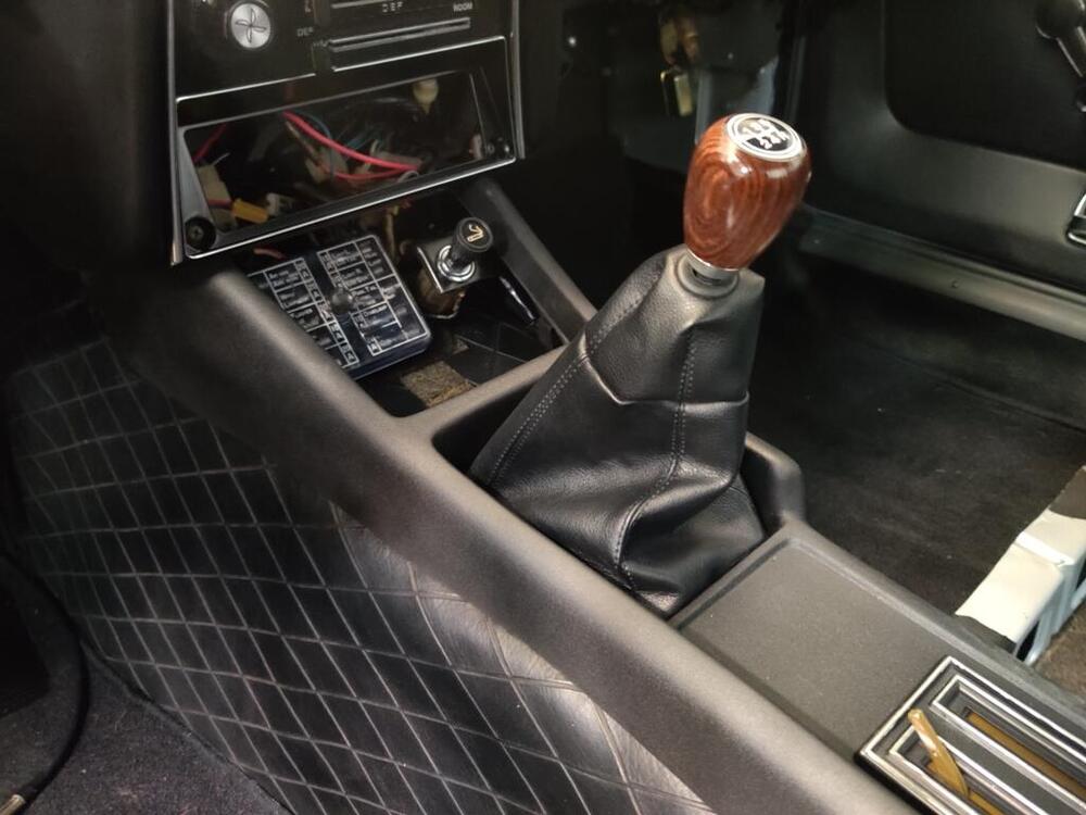
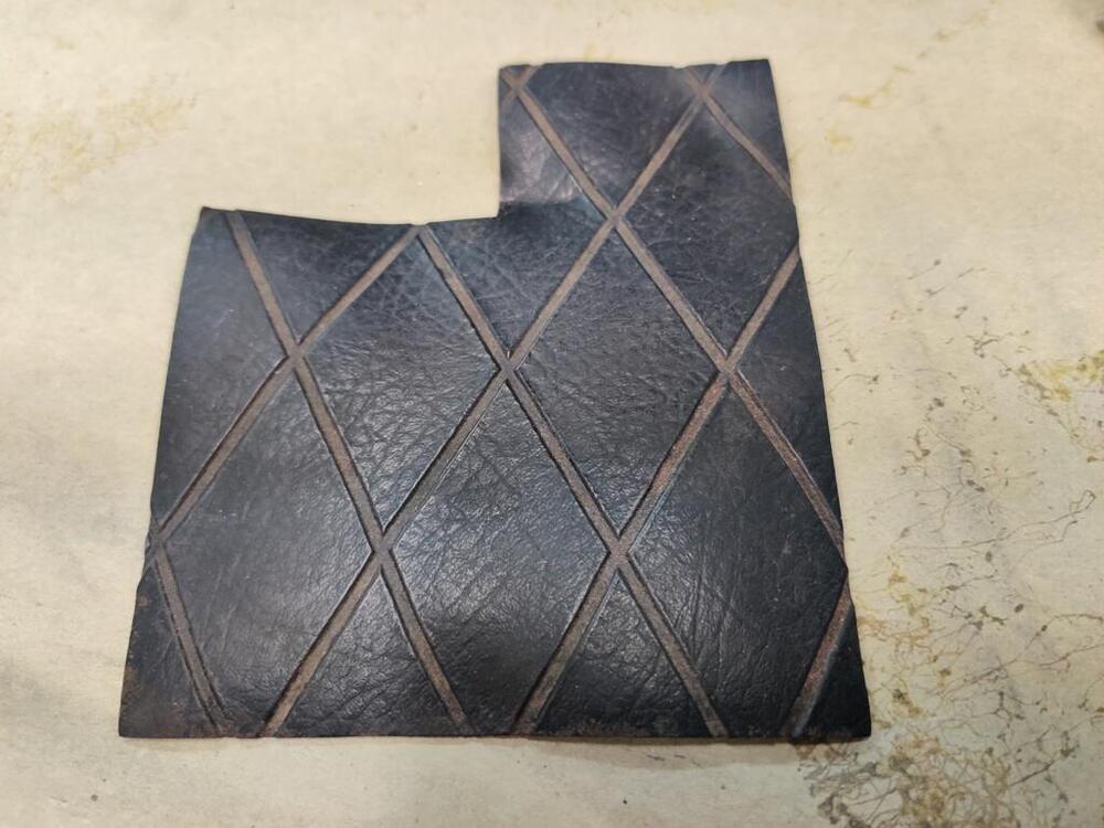
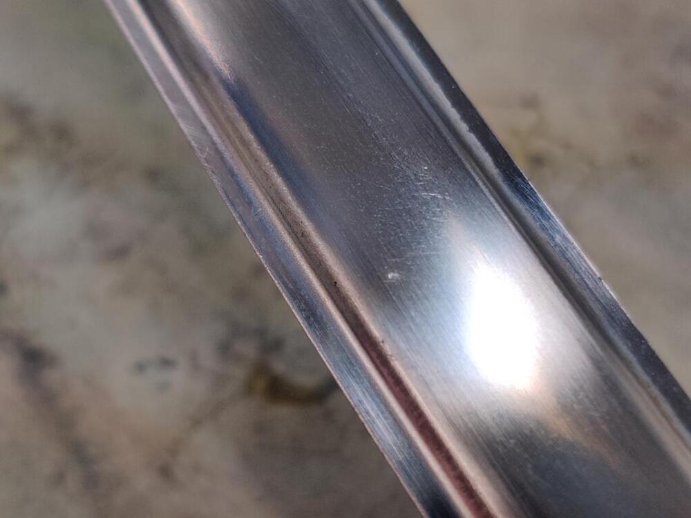
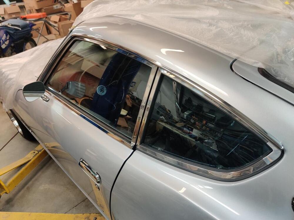
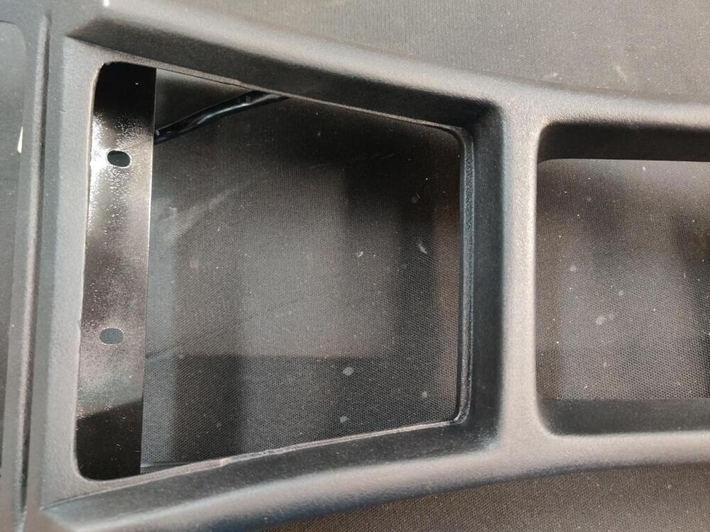
Here are a couple of pictures of the restored center console after installing it. Anyone recognize this piece of vinyl and where it goes? I am thinking it is glued to the top of the transmission tunnel under the ash tray? I started working on stainless trim today. I was able to polish the rain rail pieces without too much trouble. To polish them, generally, I used 1000 grit, then 1500 grit, then 2000 grit, then 2500 grit, followed by a soft rag and some metal polish. All of that was done by hand. I did both sides and installed them. Then, I moved on to the front windshield stainless trim. There were some rock hits, like this one in the trim pieces: To address these, I used a small metal hand punch and a hammer to push the dents out from the backside of the trim. Some experimentation with amount of force assists you with figuring out how aggressive to be. Once I confirmed that I had pushed the metal slightly outwards instead of inwards, I used 320 grit on a paint stick to "mow down" the high spot I had created. If you look closely, you can see when the 320 grit has leveled the high spot. From there, I double checked my work by using 400 grit, then 600 grit. At that point, I took another picture of the spot above: You can see the tiny nick still present, but there is no longer a dent. From here, I may try one more time to raise that nick and go with 320 again. Or, I may just move on to 800, 1000, 1500, 2000, 2500 and then polish. I figure I have about 2-3 more hours of work to get the front windshield and rear hatch stainless trim pieces done. Also, I put up a classified ad for the top center piece, as I just realized that was missing from the car when I bought it. If you have a nice one you will part with, let me know please.


-
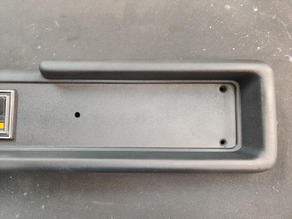
View Advert WTB: Windshield stainless steel trim Windshield stainless steel trim piece - top piece needed - 72811-E4100 Item number 3 in the url: https://www.carpartsmanual.com/datsun/Z-1969-1978/body-240z/windshield. I didn't realize I did not have this part and I am trying to get the car ready for Zcon in September. Can you help - do you have nice one? I have one, but it has a few dings and would require a lot of work to make nice - I am running out of time. Let me know if you have a nice one that won't need more than maybe removal of one light ding and some polishing. Garrett Offered by: inline6 Date 08/19/2024 Price $80 Category Parts Wanted Year 1971 Model 240z
-
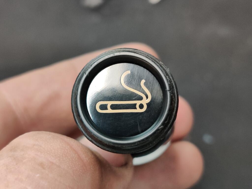
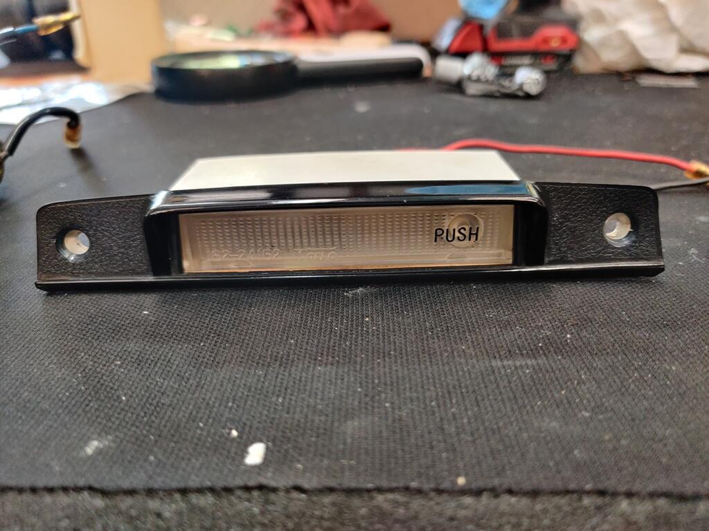
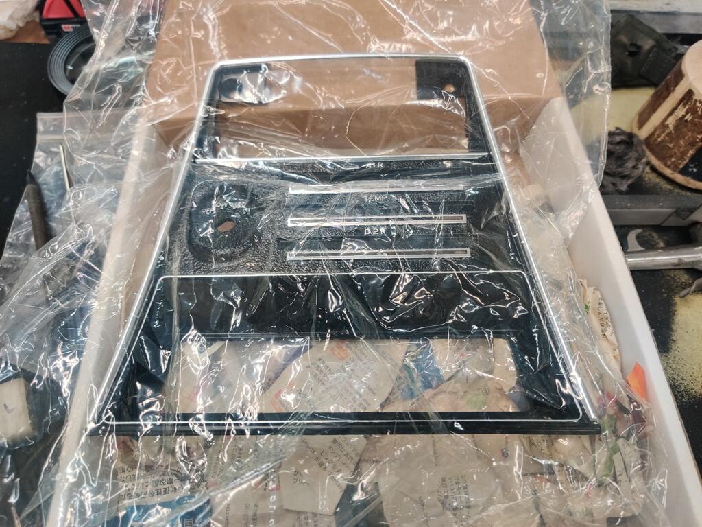
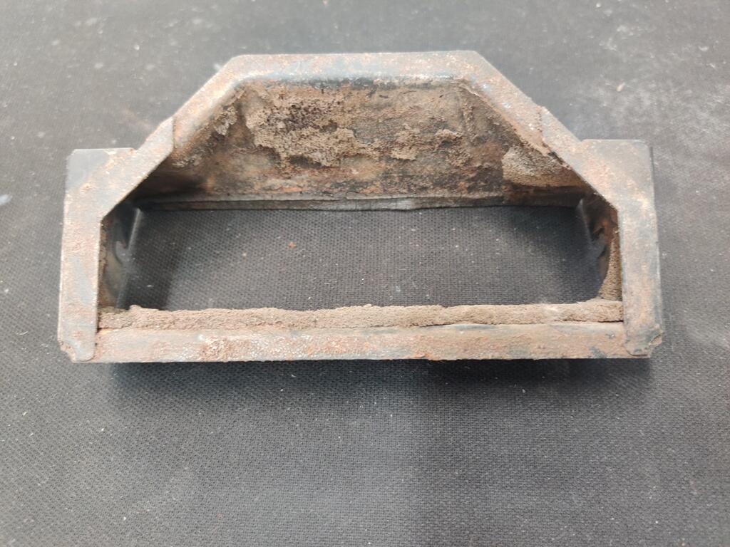
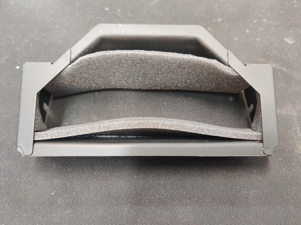
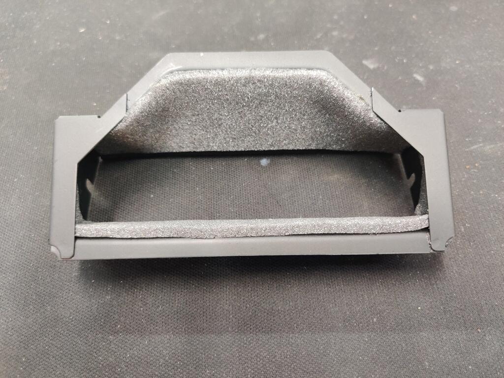
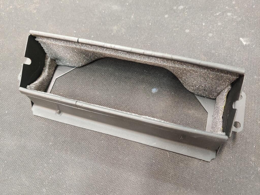
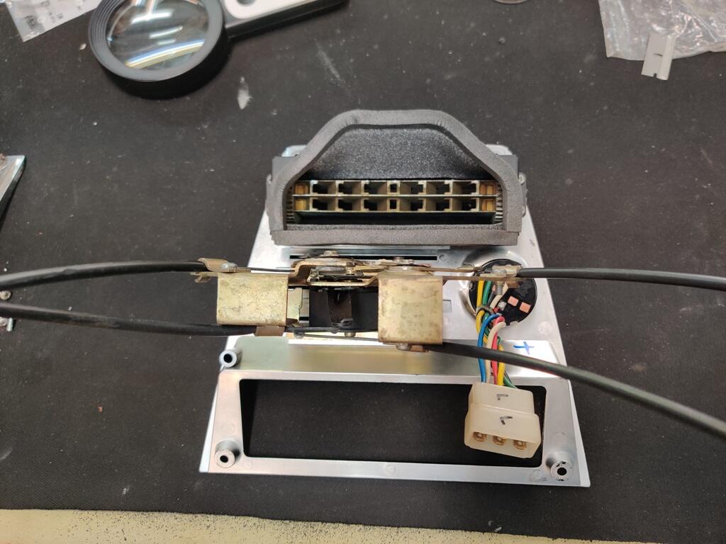
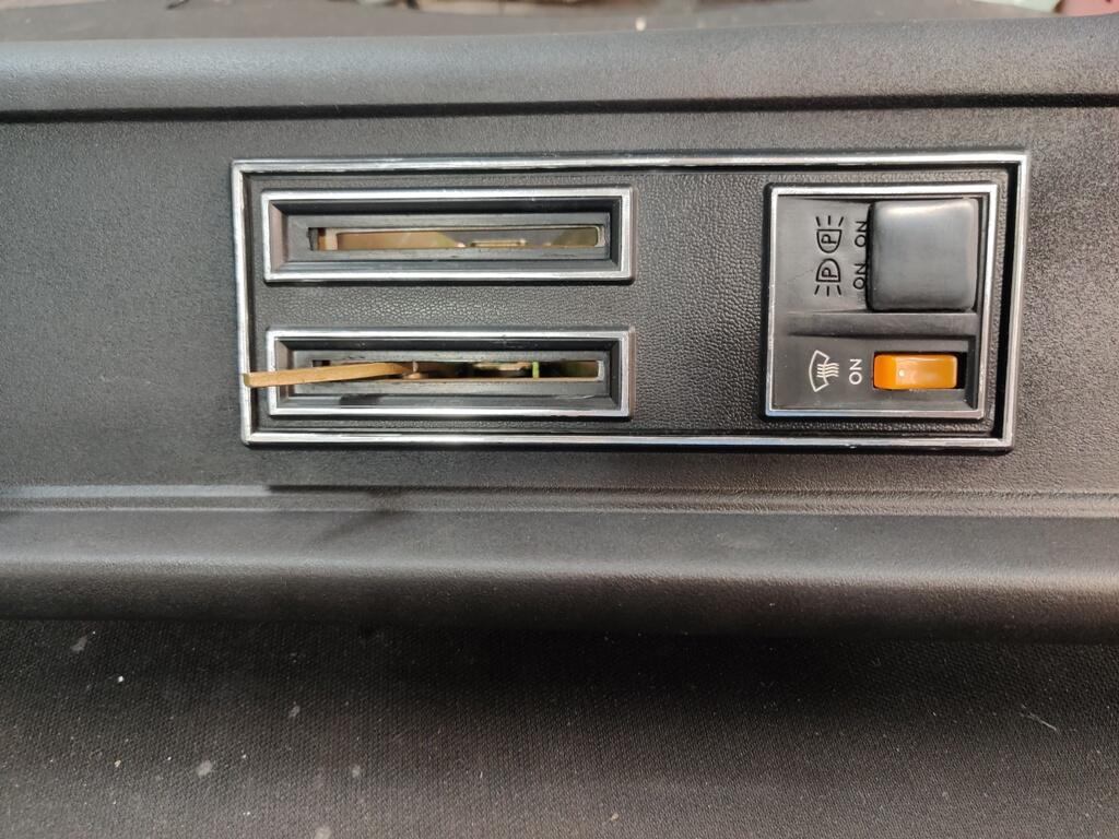
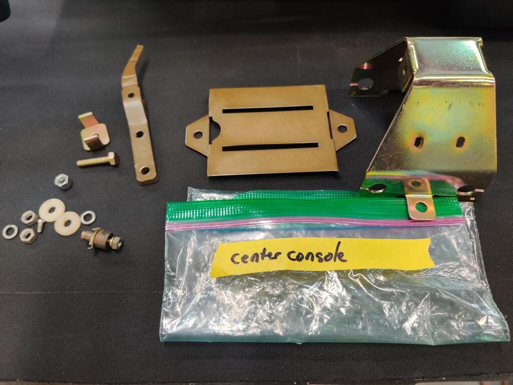
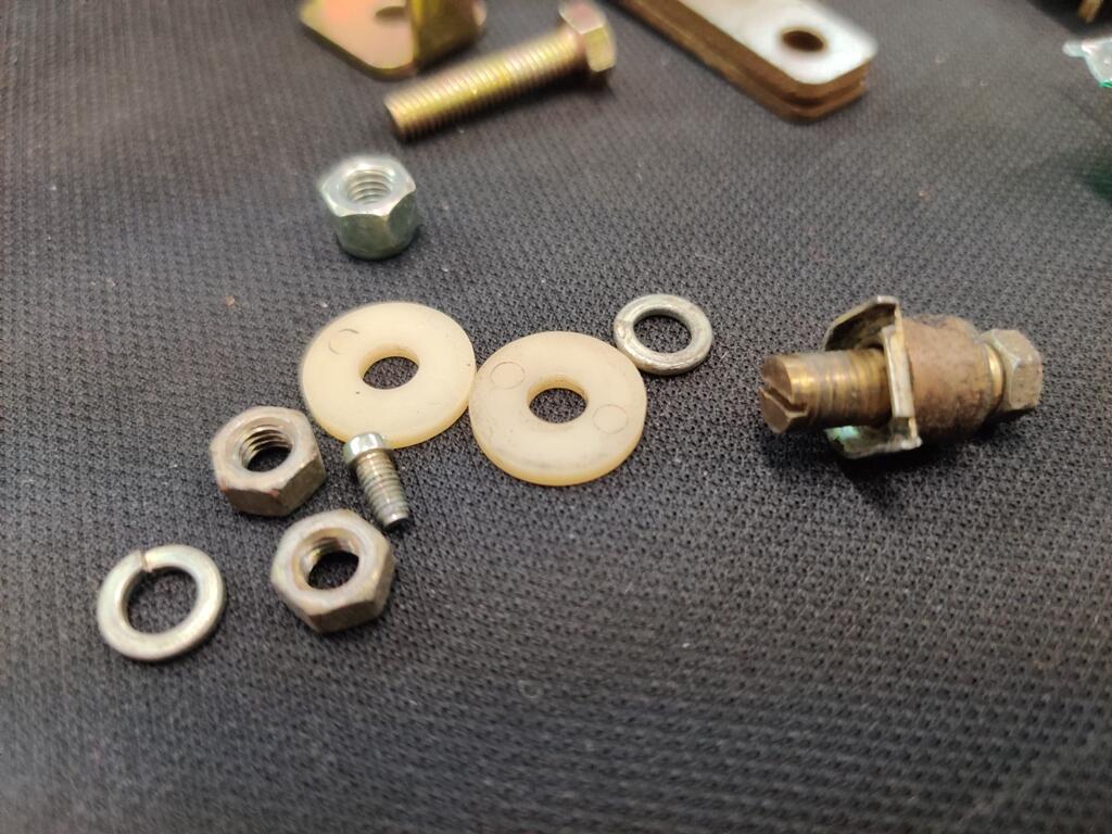
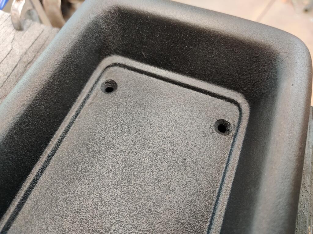
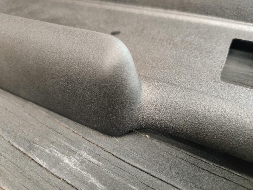
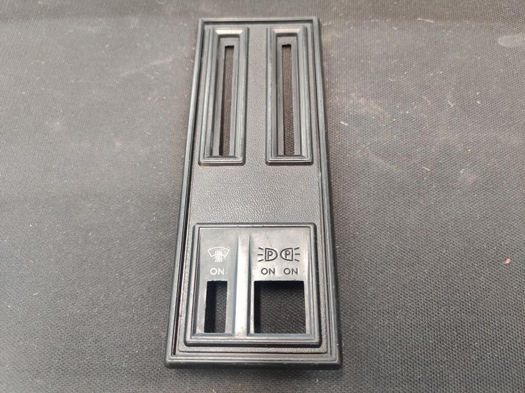
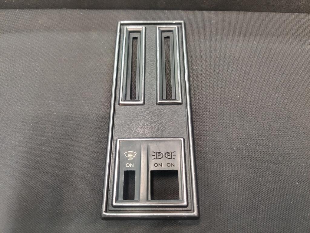
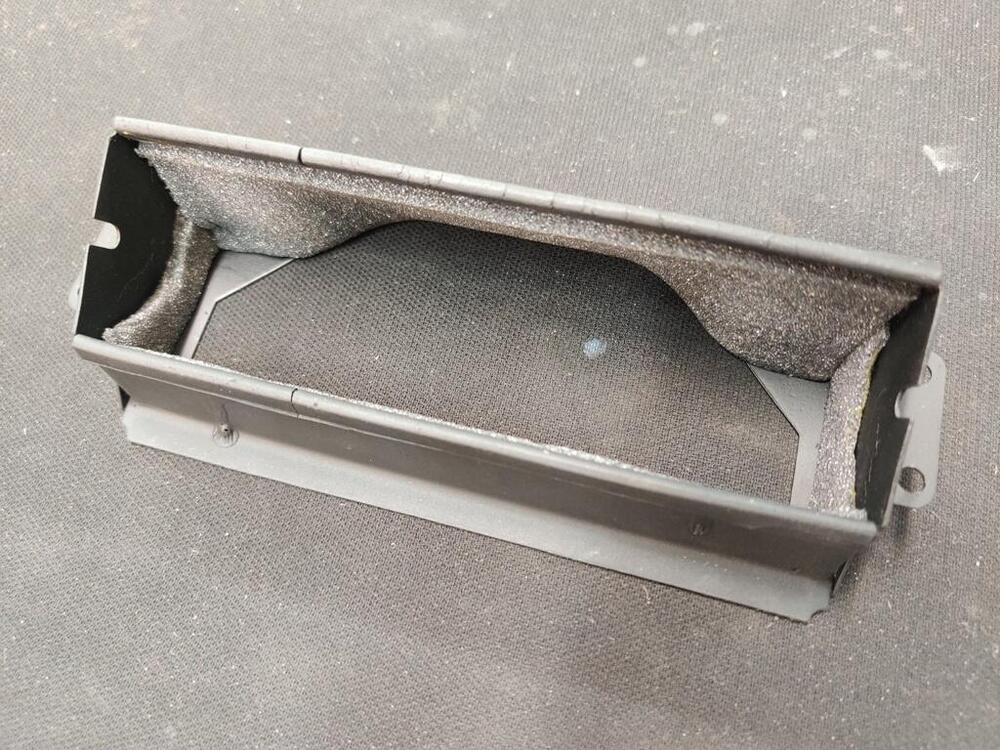
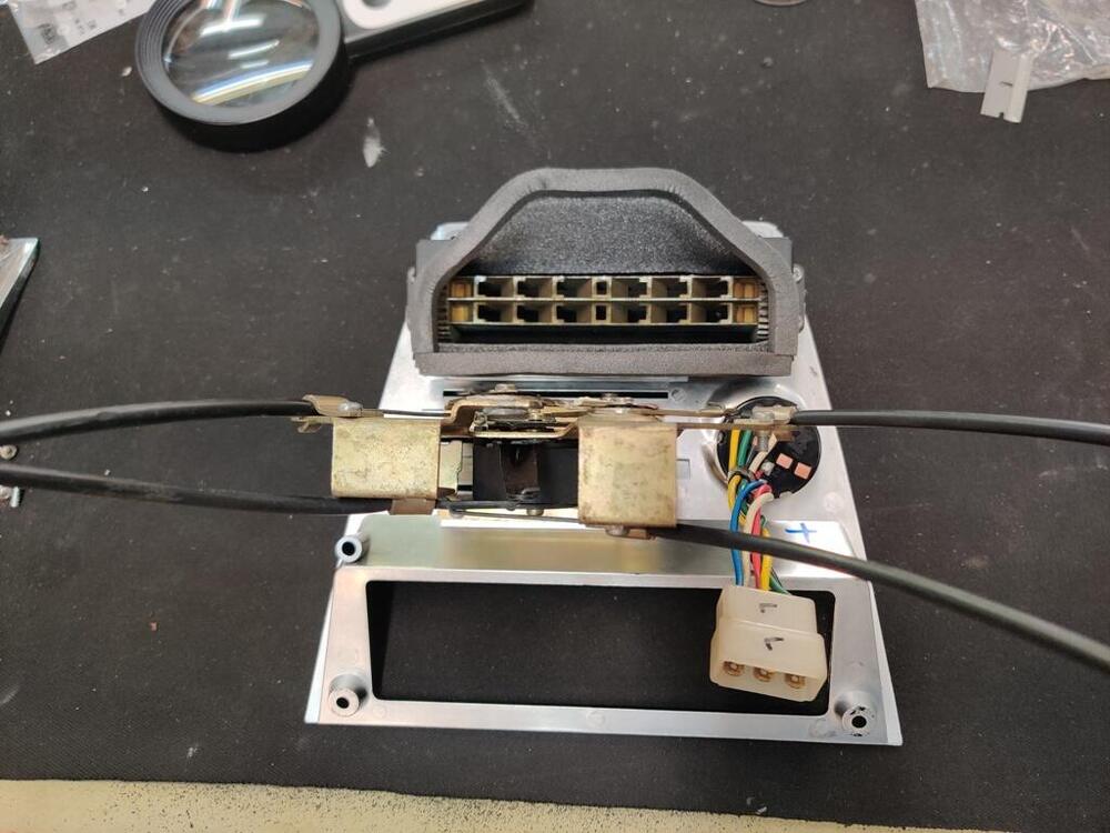
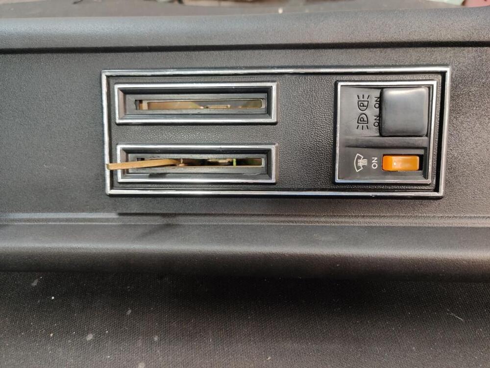
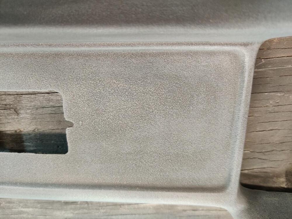
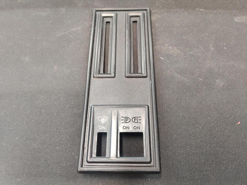
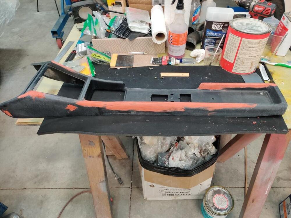
I didn't have much time this weekend to work on the car. Main accomplishment this weekend was getting a suitable shift boot installed. I didn't take pictures, but basically I used a stock 240SX rubber shift boot and a metal ring to seal up the hole on the top of the transmission tunnel. The 240sx transmission fits nicely in the car, and places the shifter in the stock location (unlike the 280ZX transmission). To seal the tunnel opening, which I left stock (uncut), all I had to do was bend the metal sealing ring at the edges. The diameter of the boot and the associated ring is wider than the top surface of the tunnel. So, by bending the metal ring on the sides, it folds those downwards. It took a while to get it shaped properly. To install it, I drilled holes in the top of the tunnel sheet metal and installed rivnuts. This is one of the very few (and insignificant)sheet metal modifications on the whole car. However, removing the 240sx transmission and installing the stock boot, etc. can easily be done. In addition to finishing the center console, I am in including some pictures from earlier work restoring the map light and cigarette lighter. Interestingly, the little picture of the cigarette is not painted on. If you remove the little disk from the lighter, you will see it is two pieces of plastic, one white and one black. The cigarette with smoke rising off of it is actually part of the white backing piece. So, you can sand and polish the disk without worry of "erasing" the cigarette. I also polished the map light lens. The map light as disassembled, electrical parts polished, and then reassembled. I took apart the center dash controller, cleaned and lubricated everything, then reassembled it. For all of the cables, I removed the metal wire from the plastic sleeves and straightened any kinks, polished the wire, and reassembled them. Center panel is an aftermarket reproduction part. I found that I had to file the opening for the fan switch a bit (off of center) from its original location to get the fan switch to align with the off, low, med, and high settings. Stripped old foam and paint off of this piece, cut new foam and glued that in place. There is a metal strip that gets glued to the center console on the front inside surfaces. The old glue was still present and helped me "locate" the strip in the correct location after I glass bead blasted and painted it. The glue I used was a 2 part epoxy (which incidentally has a similar appearance to the glued used originally). For the starter cables, I replicated what I did for the center panel cables. I removed the hard wires from the cable housings, carefully straightening any kinks, and then used metal polish to clean the wires. For the cable housings, I sprayed WD40 inside of them and then blew them clear with compressed air. I then rubbed lithium grease on the hard wires and reinserted them in the cable housings. The console fit nicely when I finally installed it today. I didn't get any pictures showing the installation of the reproduction shift boot, but that fit well. It looks stock, which is nice. The center console was one of the big projects left to do and it feels good to have that done.


-
Revisiting progress on my list: Machine shop to remove a small amount of material from the left side flange of the differential Part has been shipped off for machining. Hoping removal of .5 mm will go without issue. Send driveshaft off for balancing, but... I have to put the differential in car and check drive shaft fit first. I may need to remove some of the shielding on either the rear of the transmission or the driveshaft. Waiting for the machined left retainer to come back so I can do final shim adjustments to get backlash into specification. Tell Snake Oyl to proceed with the restoration of the seat belts I sent them in June even if reproduction date tags cannot be sourced (they have delayed for weeks because they haven't been able to confirm that they can get the tags from "their vendor". Payment and additional webbing for the luggage straps sent and received. Work to restore the seatbelts should be in progress. Buy carpet in bulk (still have to decide which). Cut to fit the car and have local company put correct finished edging. Or, purchase Auto Custom Carpets, Inc. kit from RockAuto. I may purchase this kit for day to day use... and have a custom set of carpets for show. I received and installed the Essex pile version of the carpet set available from ACC (Auto Custom Carpets). Removal of carpet jute that came on carpets is not possible without damaging the carpets. I found that out when attempting to remove it from the under seat pieces. Get gas door lock and ash tray grill chrome plated by local company - quote received for one gas lock (two pieces) and two sets of ash tray parts was $200-$300. I shipped the parts off last week and they should arrive tomorrow. I was quoted 4 week turnaround, so they will likely not be back in time for Zcon. Horns - these have to be re-plated before I can put them back together - horn back plates and misc. other parts shipped to be re-plated - they should arrive tomorrow. Hoping for about a 3 week turnaround. I also have the following fairly large lift items: Assemble the seats - fit new support straps, foam and upholstery covers. Repair/restore center console - finished all the repairs and cosmetic work necessary for the center console. Ordered a 240SX shift boot ring which is the last piece I need to install the center console. Test gas tank for leaks - Put two gallons of gas in the tank a few days ago, and no leaks so far. Find source of the electrical short circuit in the windshield wiper circuit Found it with @SteveJ help. I pulled out all of the seat parts and made room on my work areas to get started. Interestingly, the old seat head rests are much harder than the new seat foam. I feels and sounds like there is some kind of core which is inside the foam of the original headrests. Also, originally they were separate parts from the seat back foam. I will take pics and show the differences. I've been searching for "rivets" that have large heads like the originals. I have found a couple of options on McMaster-Carr. Once I have suitable rivets in my possession, I can start on the seats.
-
The next episode is out. I searched on an off for days and weeks to find an undercoat that would look like the original stuff - I wish I could have known about what he used before I did my car. Anyway, read the description also - interesting info there.
-
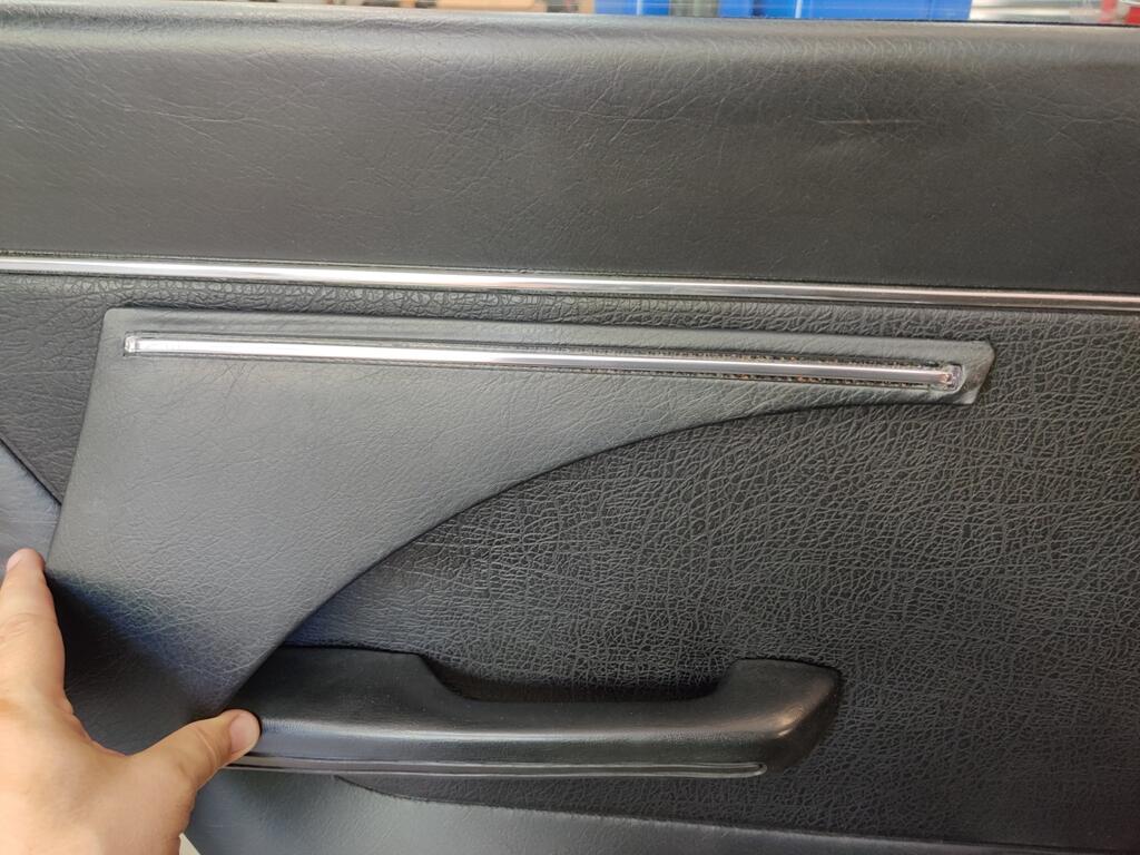
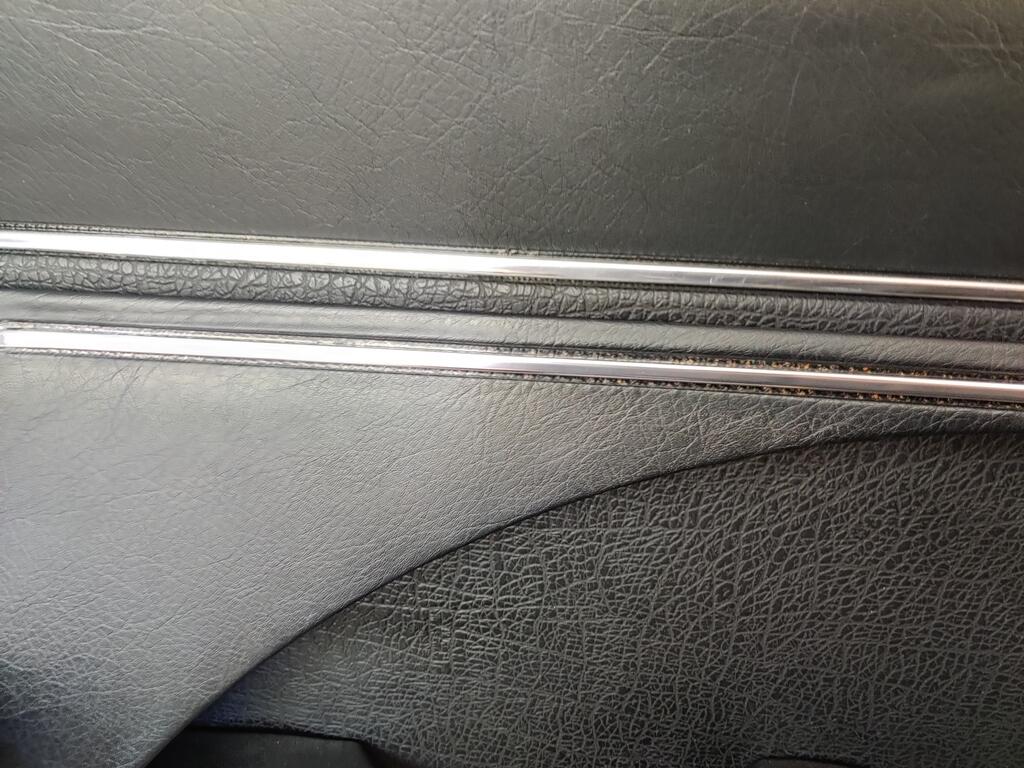
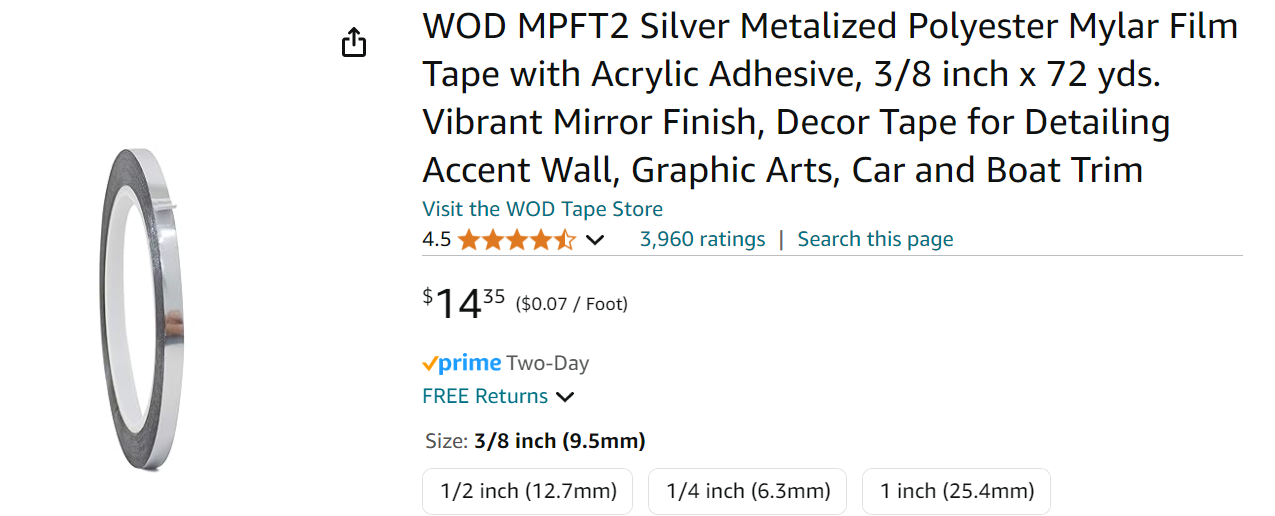
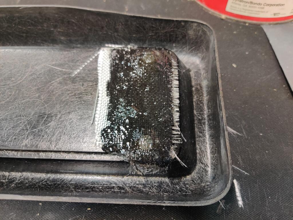
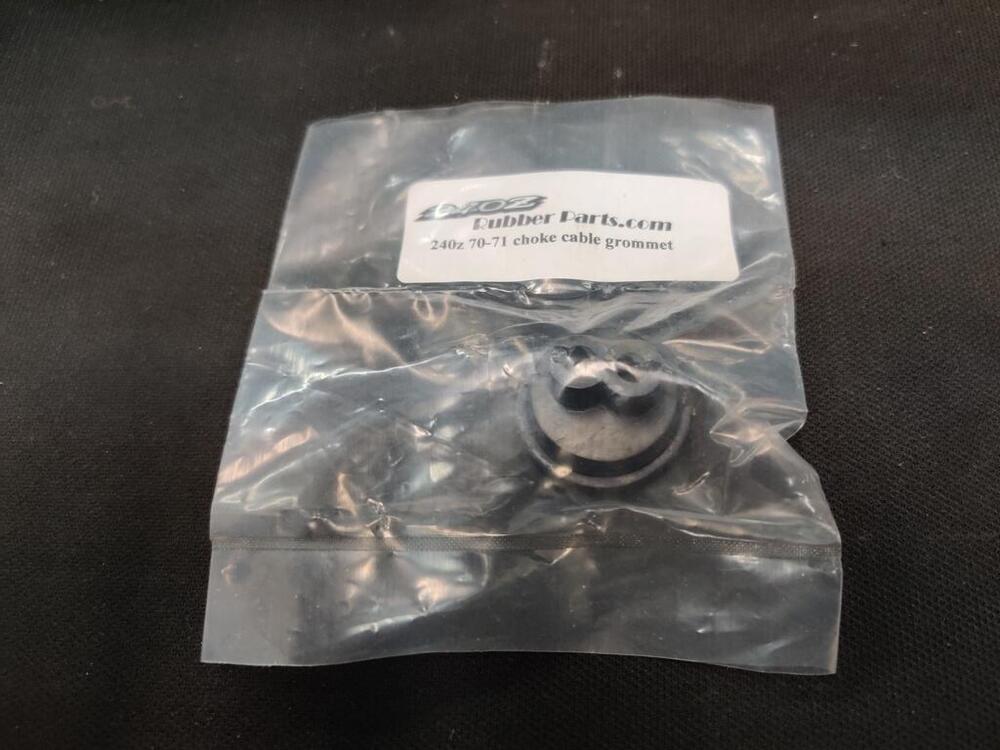
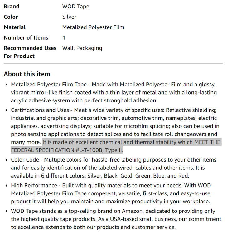
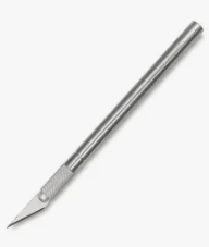
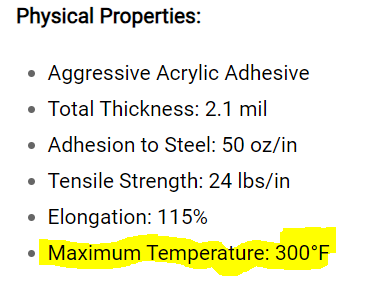
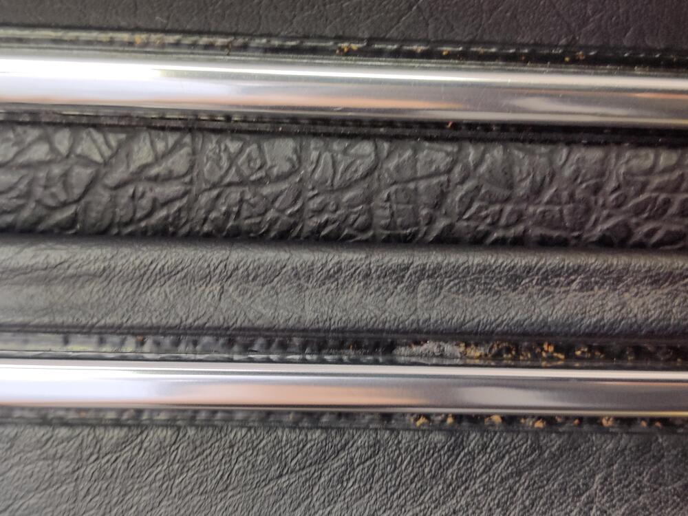
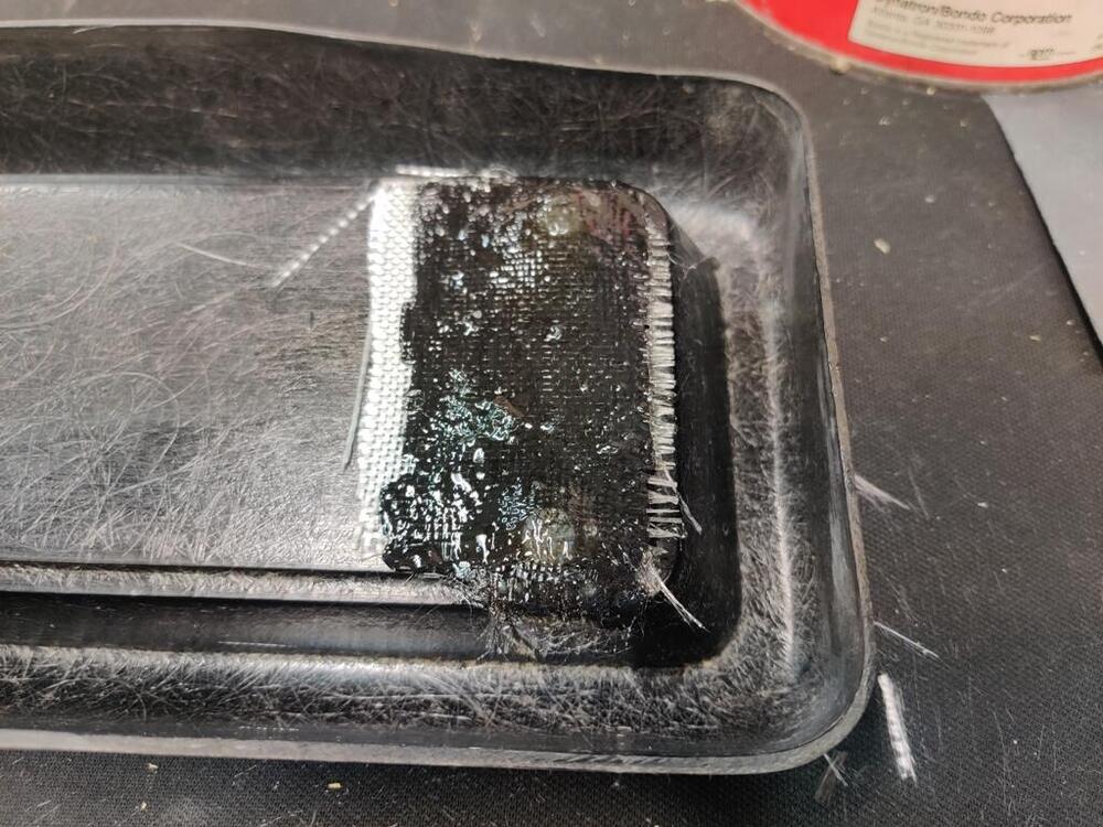
It is very sticky. For most of the failed attempts, the tape and adhesive came off together. On one failed attempt, I didn't realize that some of the adhesive had stayed behind, and when I put a new piece on, it showed underneath the new piece. Removal of the adhesive using 3m adhesive remover was difficult. The 3/8" width I bought is perfect. Where I did not apply it perfectly straight, you could see a tiny sliver of extra tape off of the edge of the part that is supposed to be silver. I trimmed that by running an X-acto knife like this along the edge and then pulled the sliver of excess off. I only needed to trim one of them for a span of a couple of inches. I found some more information about the tape. It appears it may be able to handle hot car interiors: https://www.amazon.com/dp/B079C5PYV9?ref=ppx_yo2ov_dt_b_product_details&th=1 This product appears to be the same: https://store.tapesandtech.com/mylar-polyester-tapes/mmyp-1-metalized-polyester-film-tapes.html
-
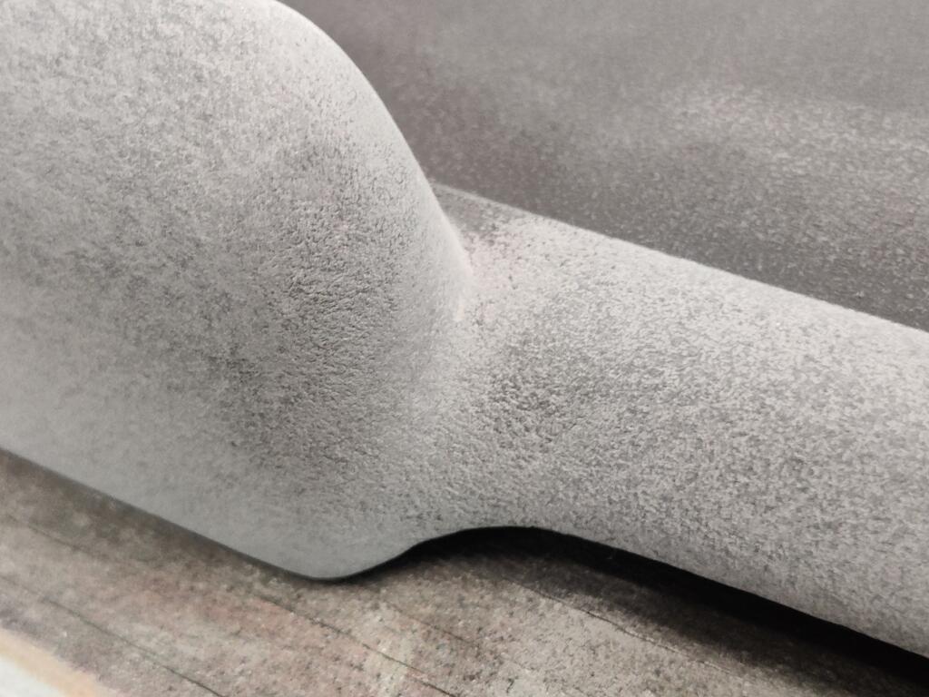
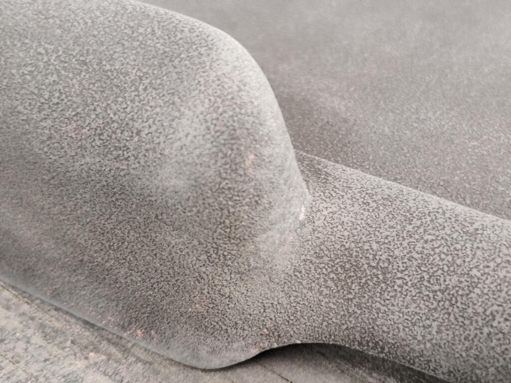
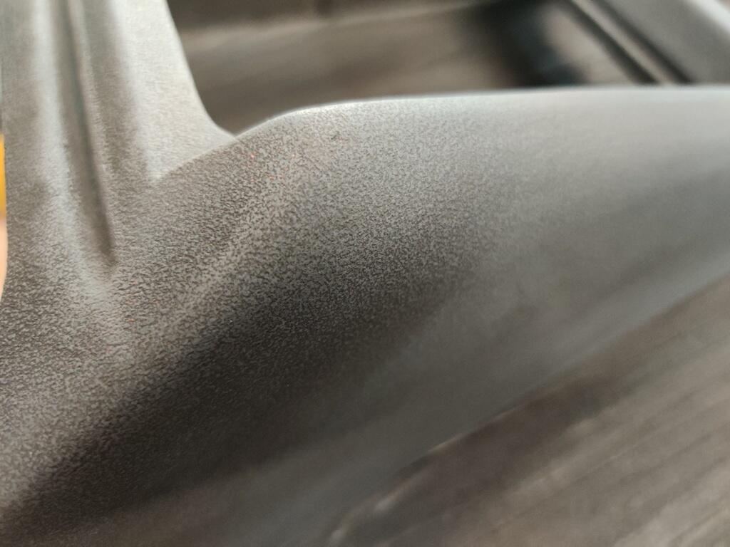
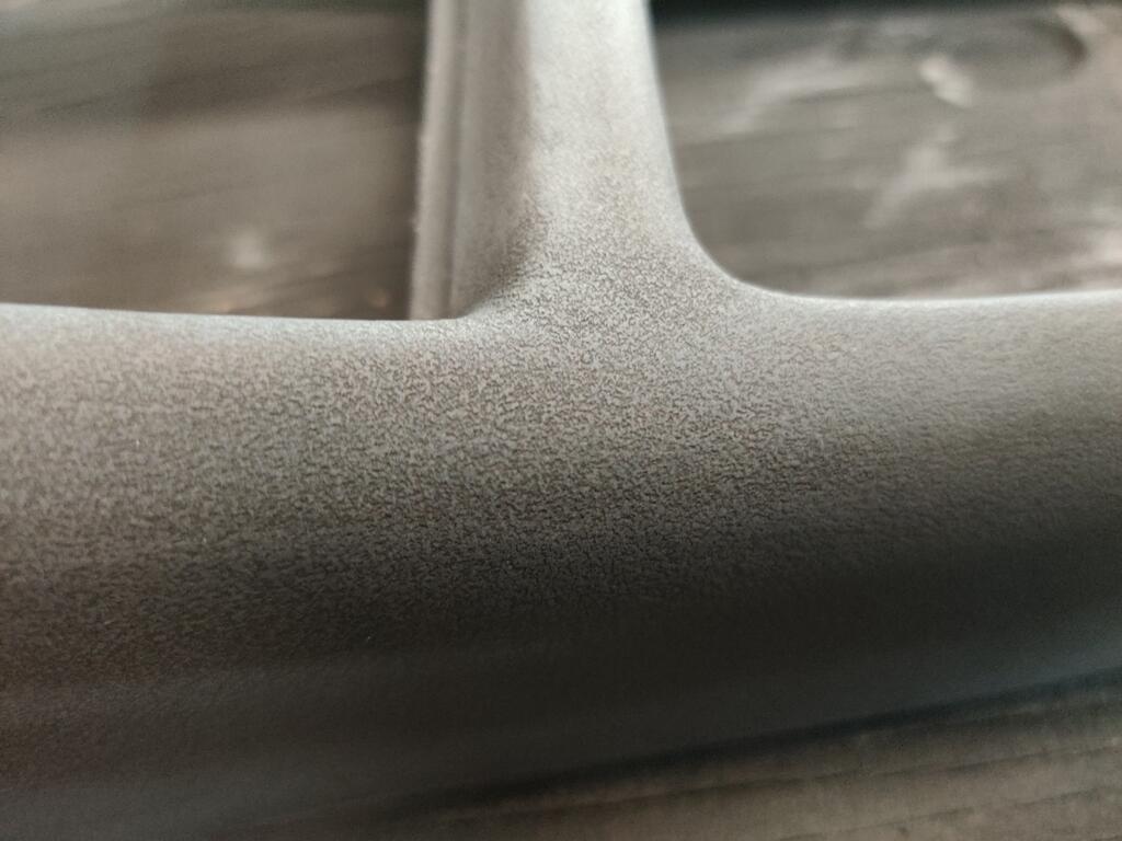
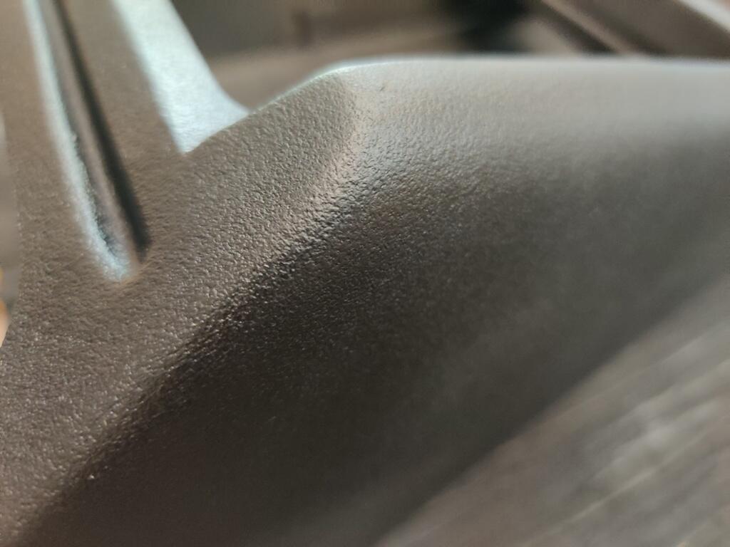
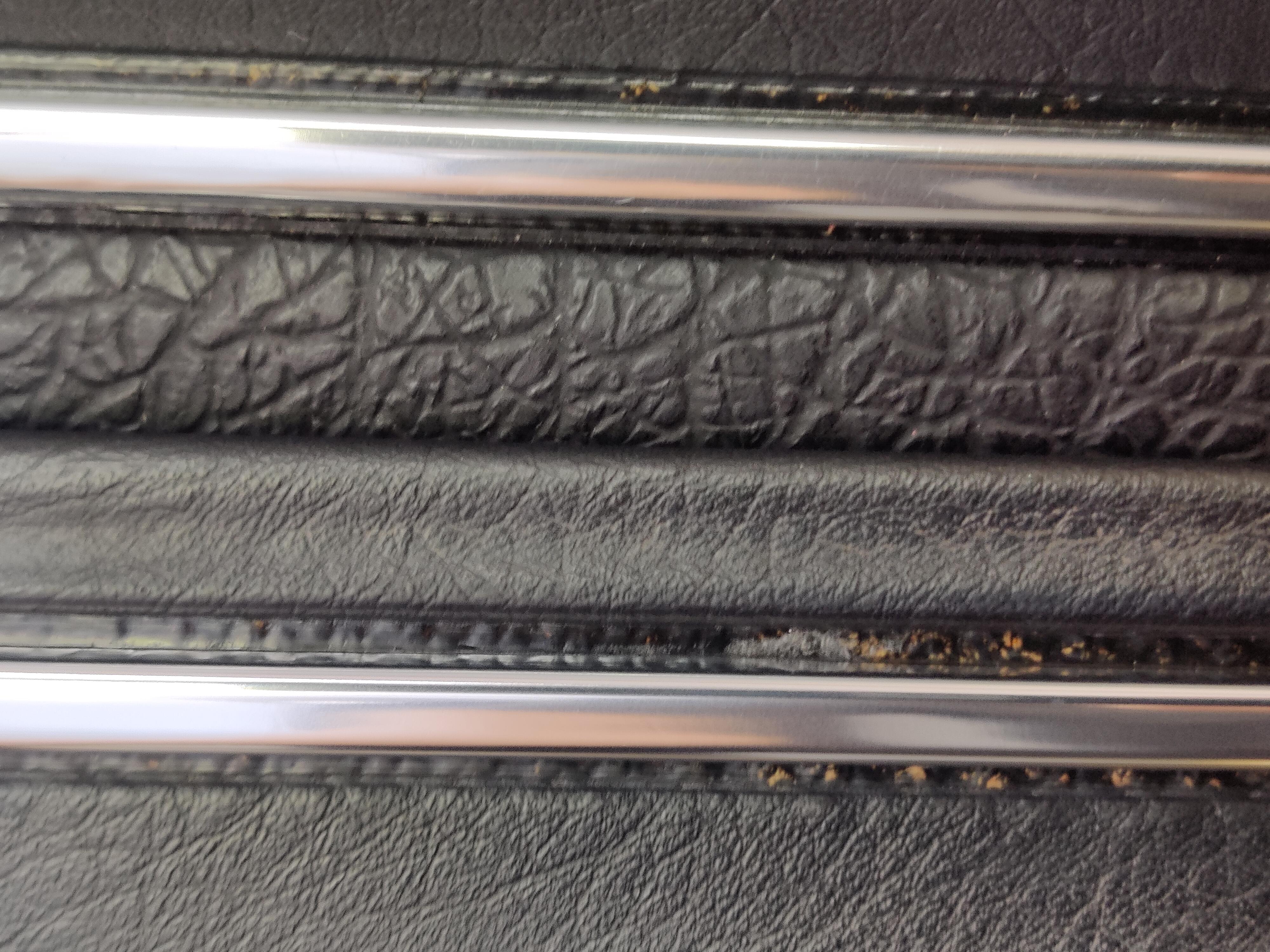
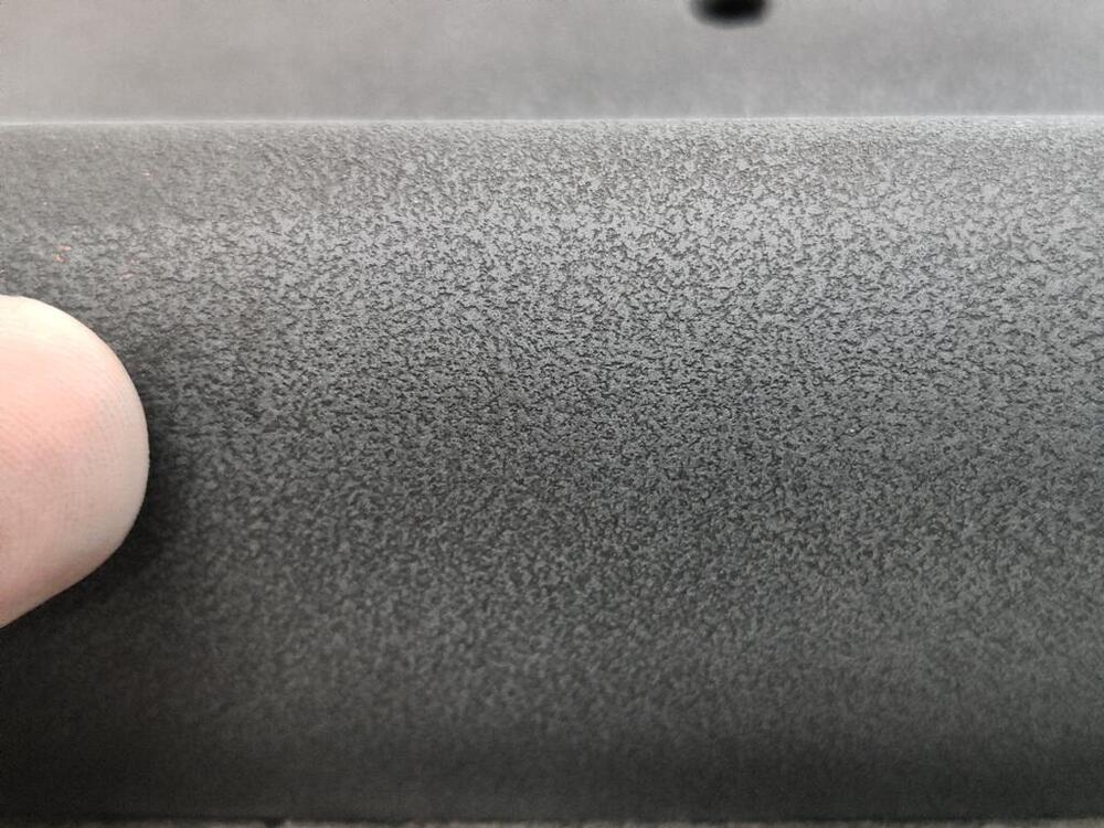
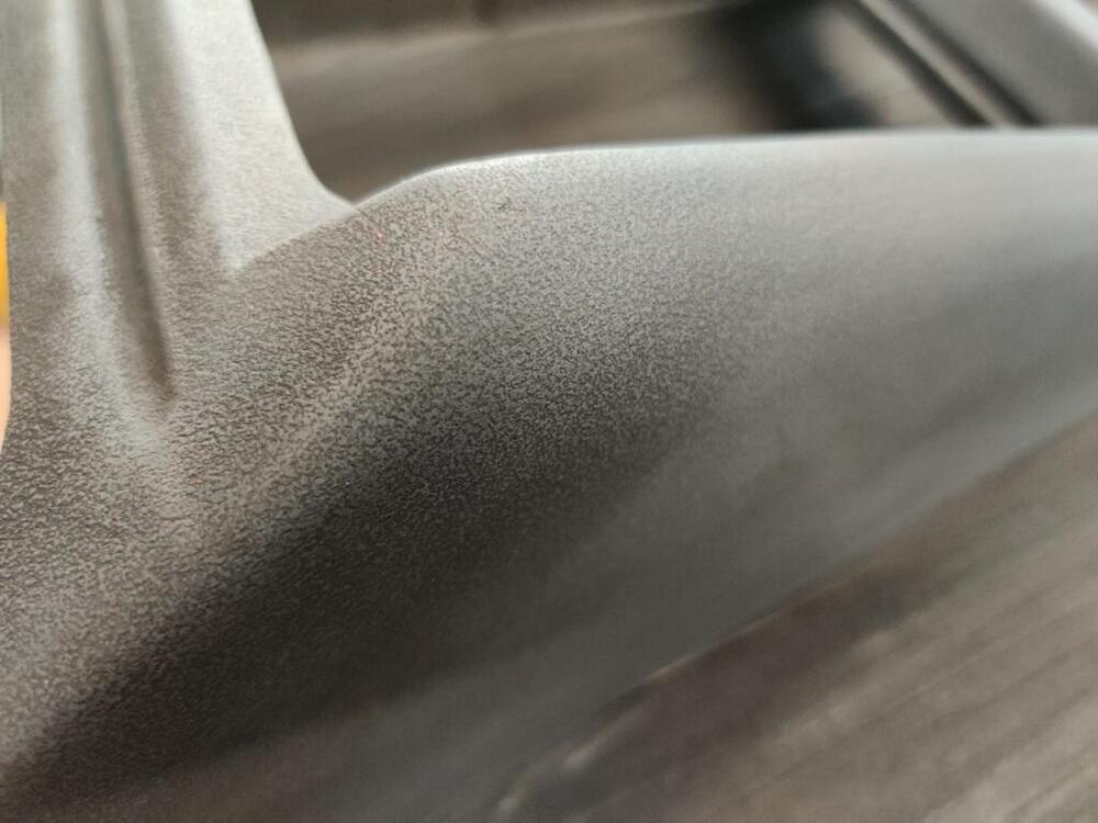
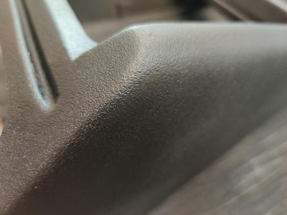
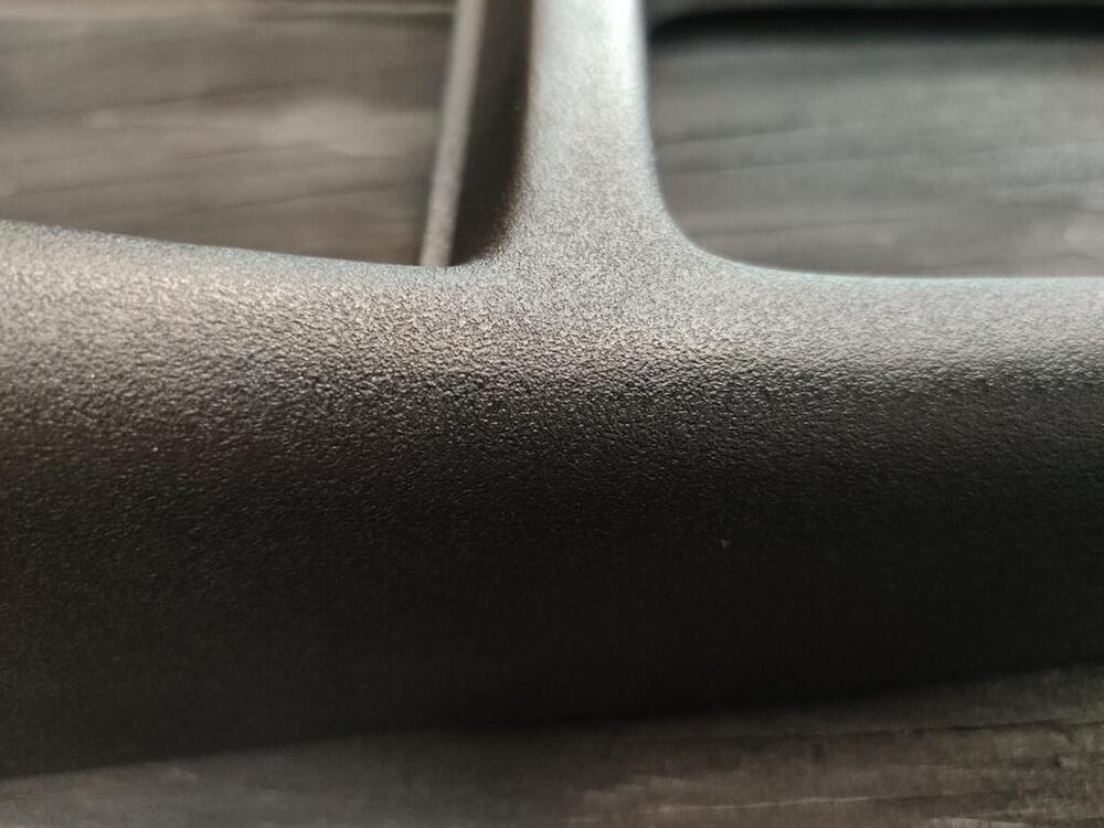
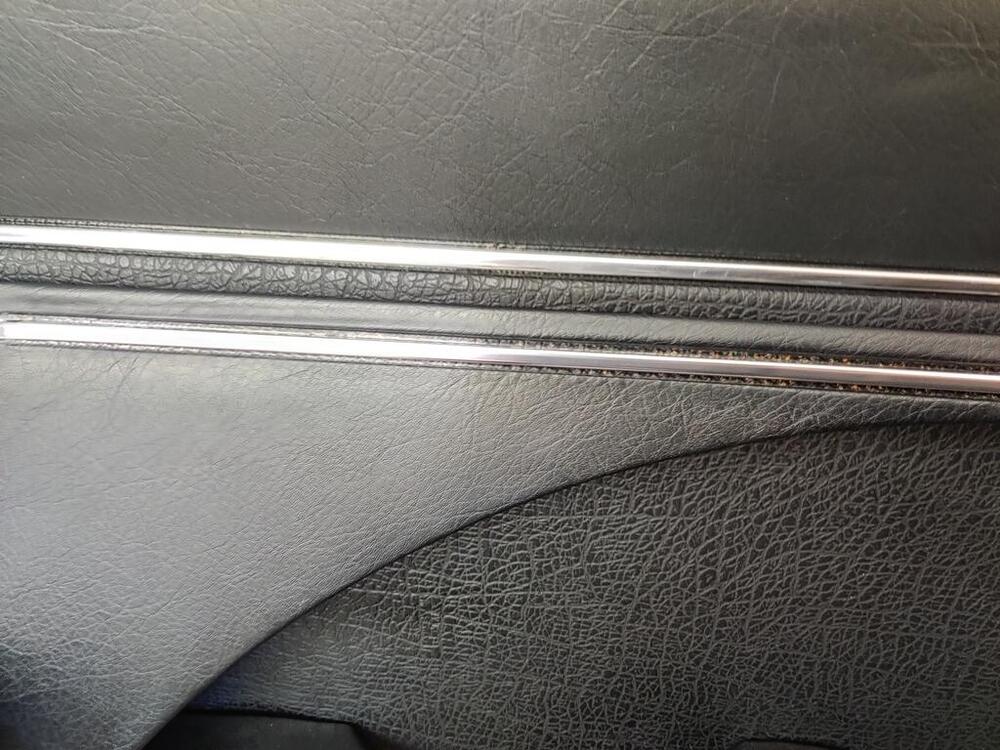
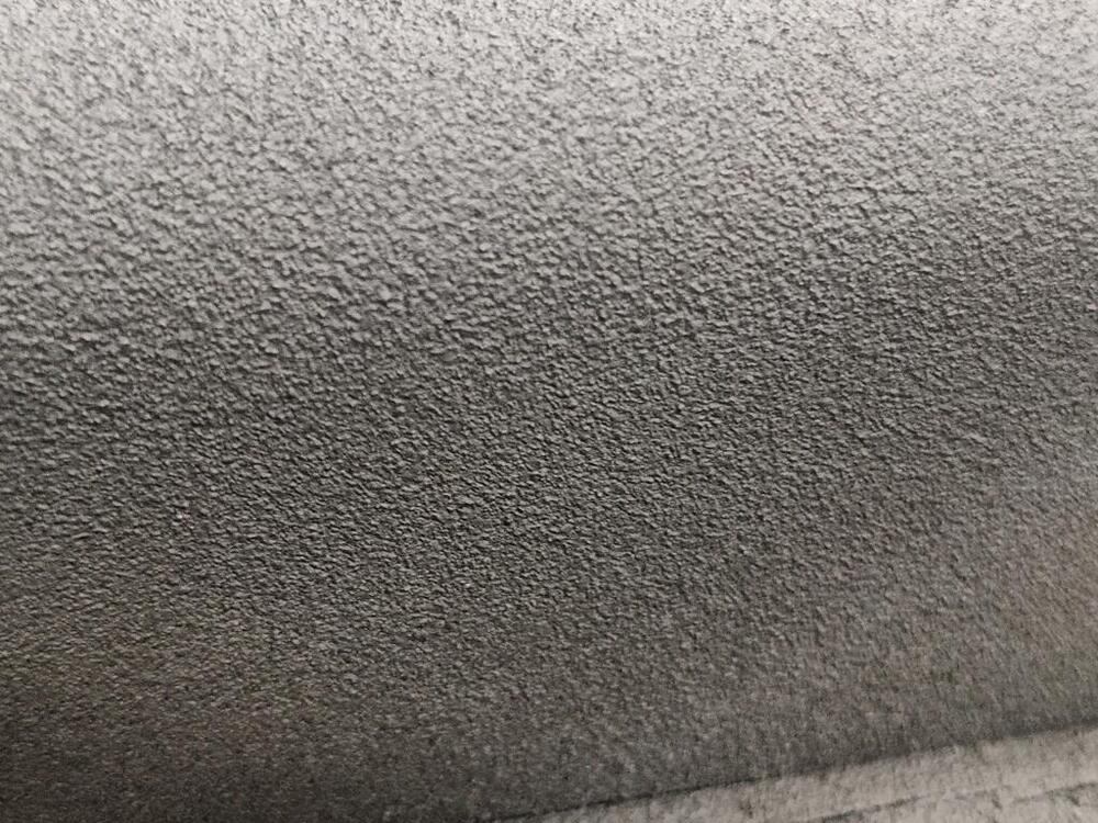
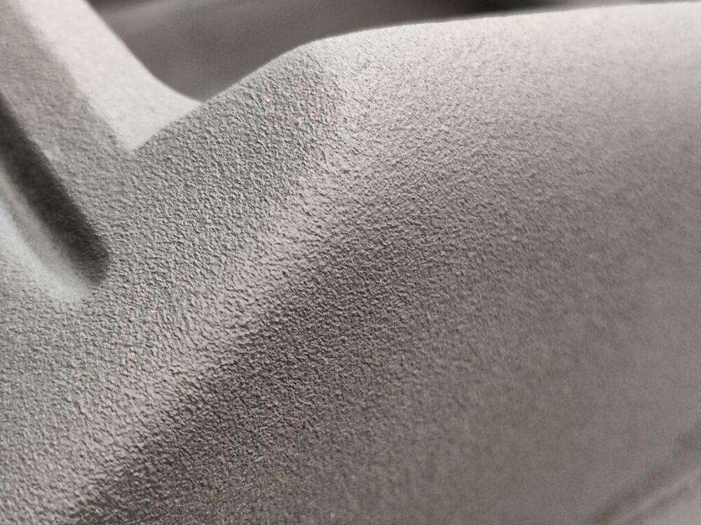
I continued working on the center console this week. I used an 800 grit sponge sanding pad and went over the texture. Here are several pictures before painting. The texture doesn't look like the factory one so much, but it is a decent approximation. From the last picture in this group of three through the rest of the pictures, the console has semi-gloss black paint applied. Another little project I completed was these interior trim panels. The silver/chrome had come off of them. I don't know what happened to my pictures of the "before", but the "chrome" stripe was blue. I found this Metalized Polyester Mylar Film Tape with Acrylic Adhesive and decided to give it a try: It took about 7 tries to get it on the panel to my satisfaction. I was getting some air bubbles on some of the attempts. And it was a bit crooked on some as well. Thankfully, you get 72 yards of it on one roll, so I had plenty to spare. 🙂 Anyway, I am very pleased with the final outcome. I hope it stands up to heat, etc. well as time progresses.


-
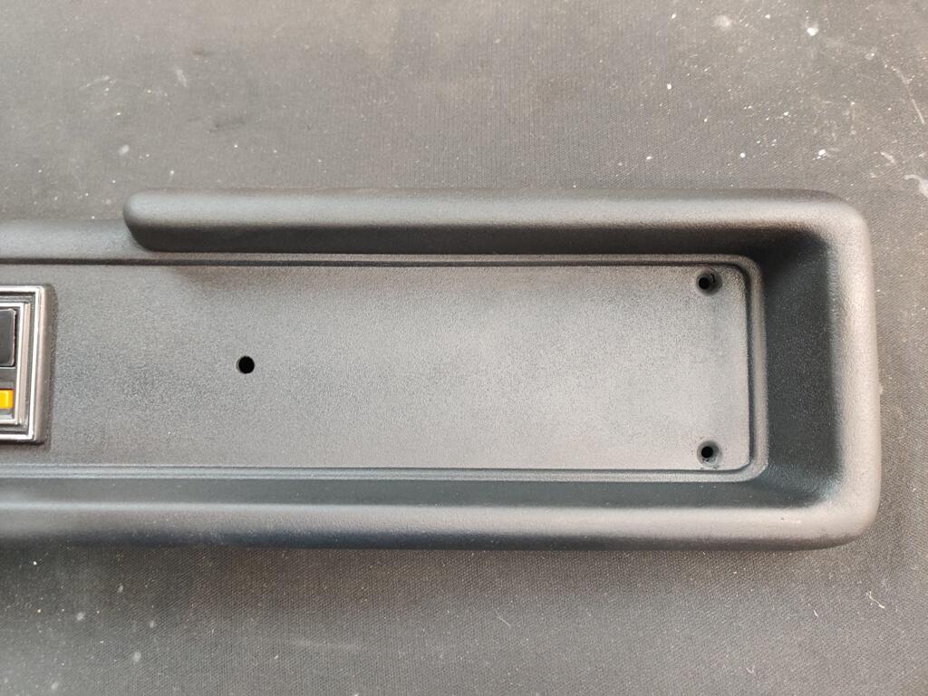
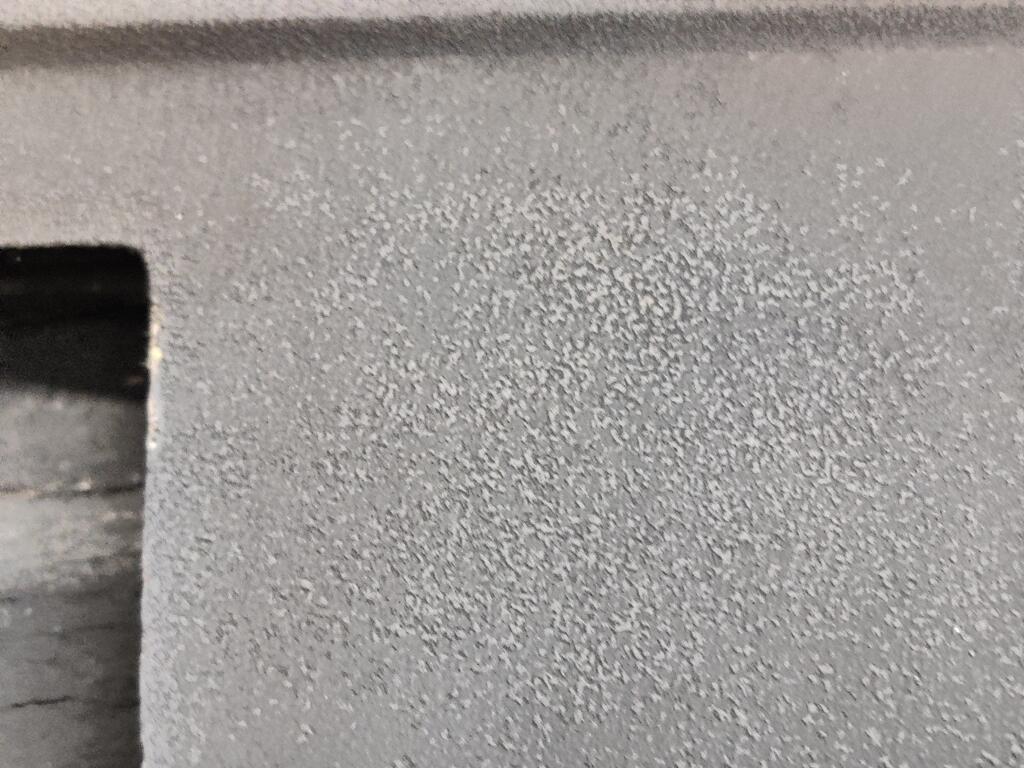
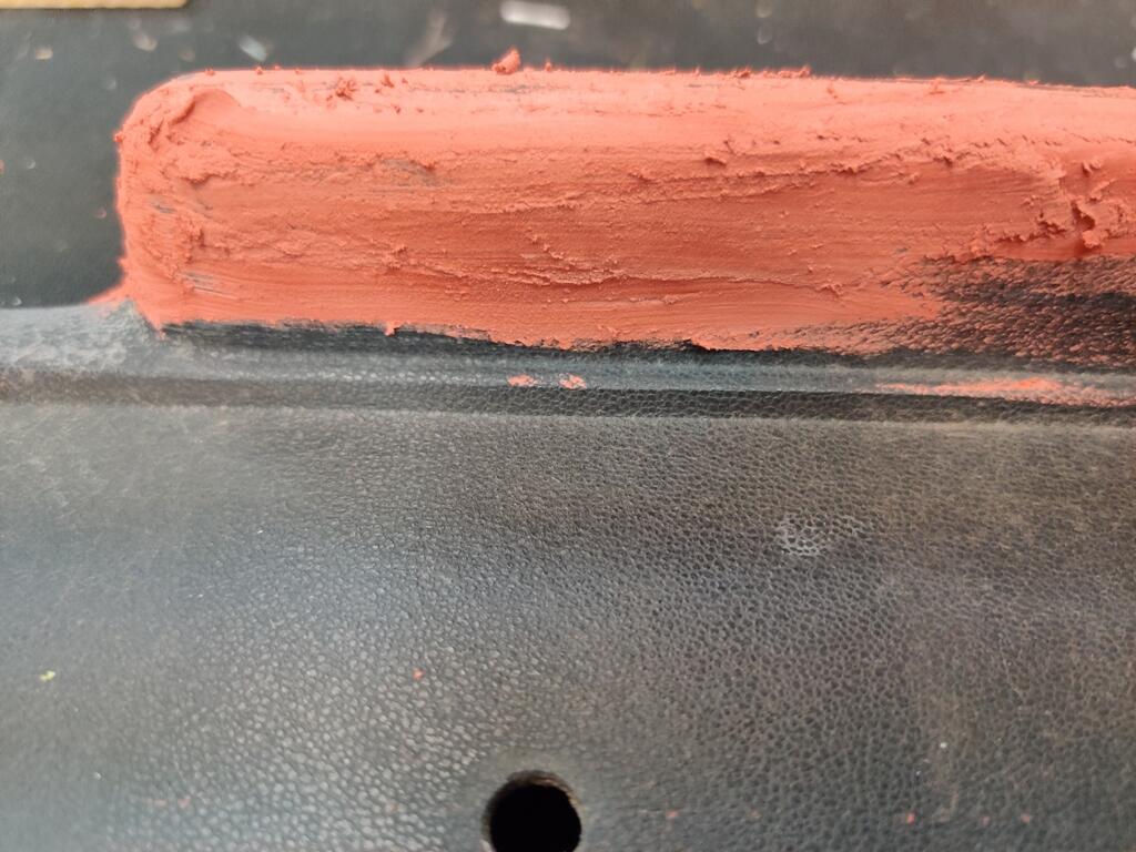
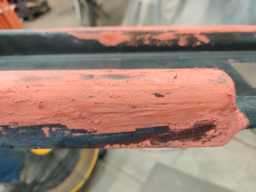
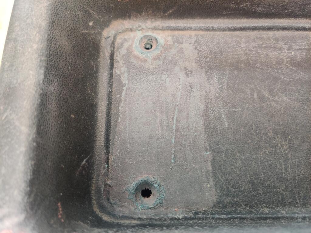
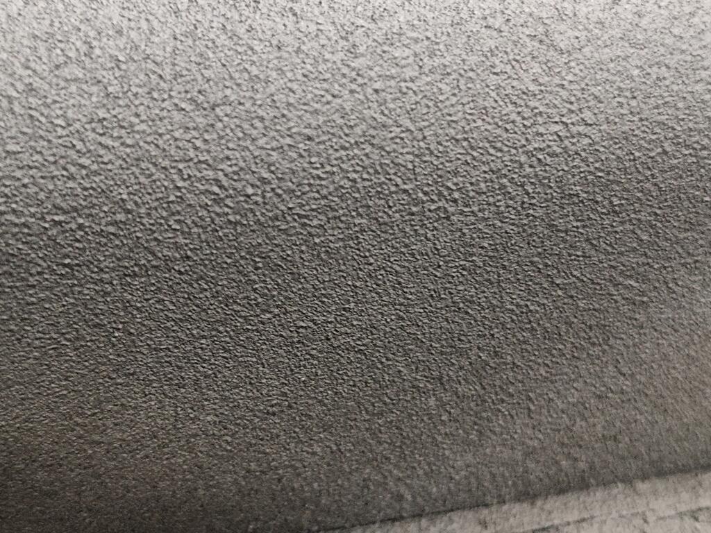
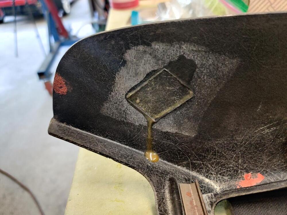
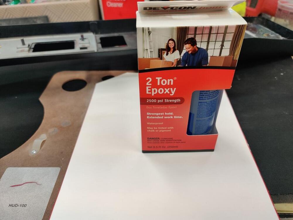
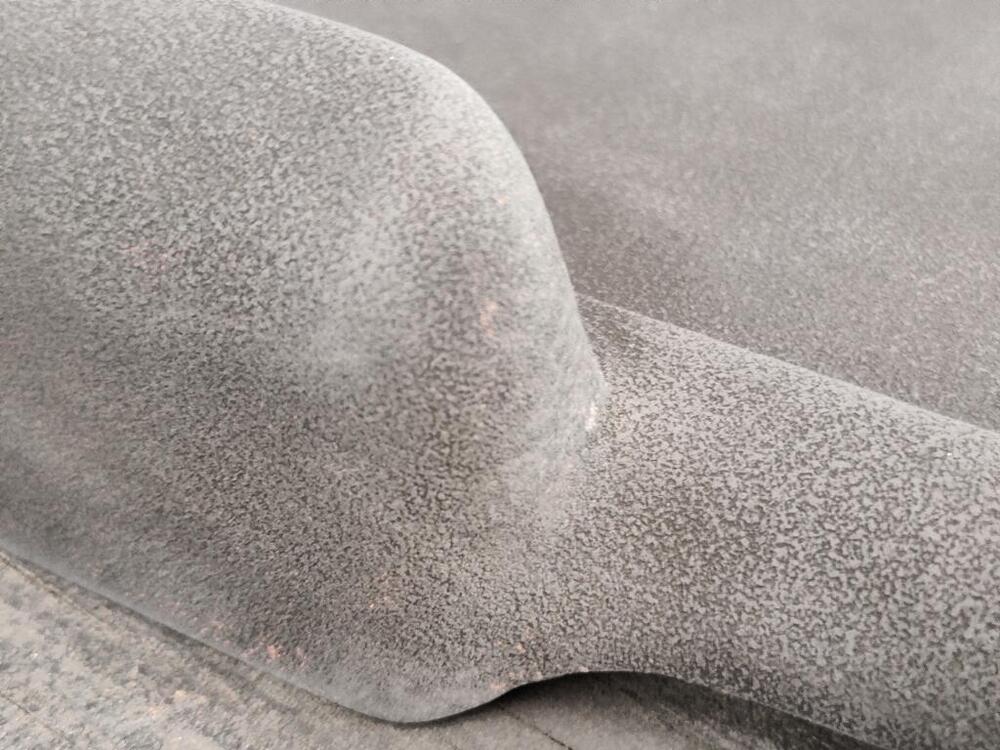
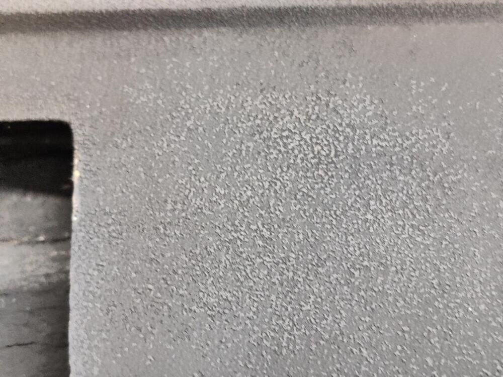
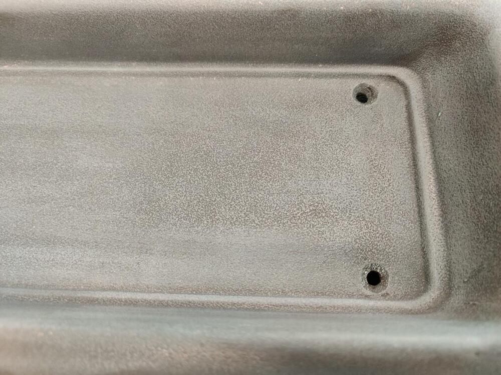
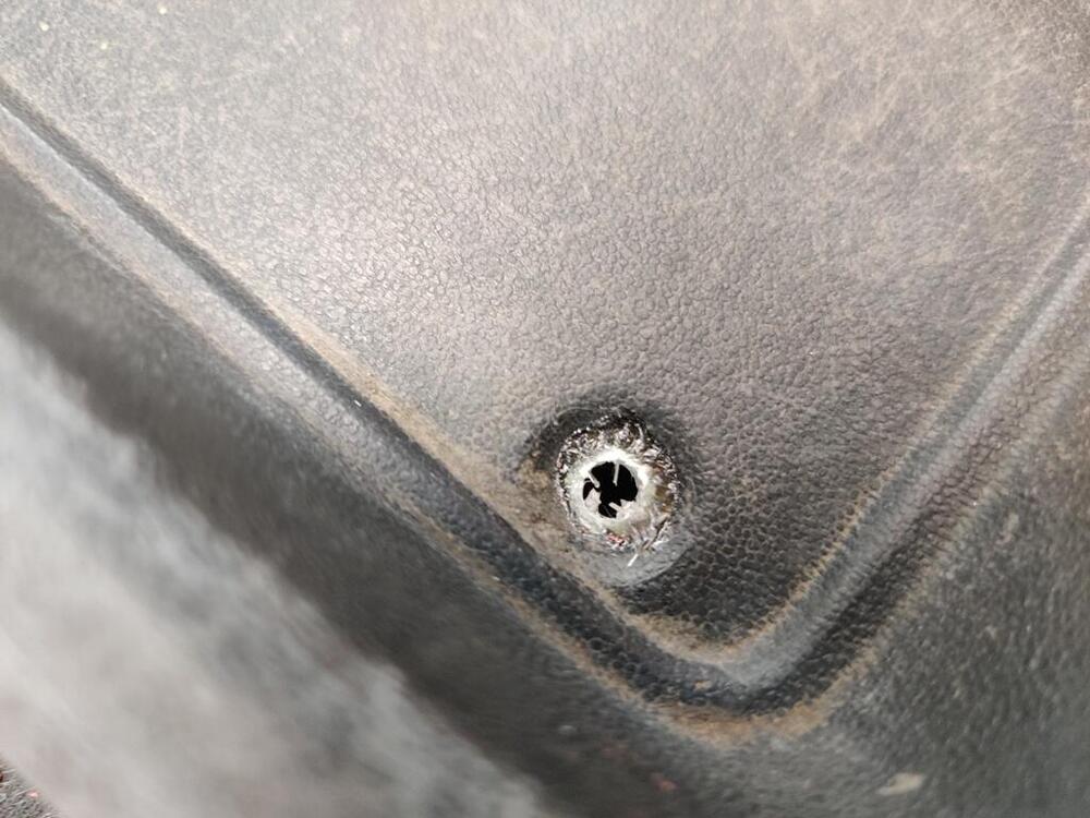
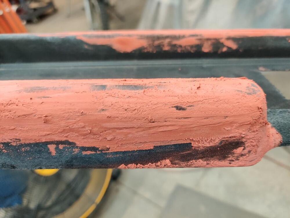
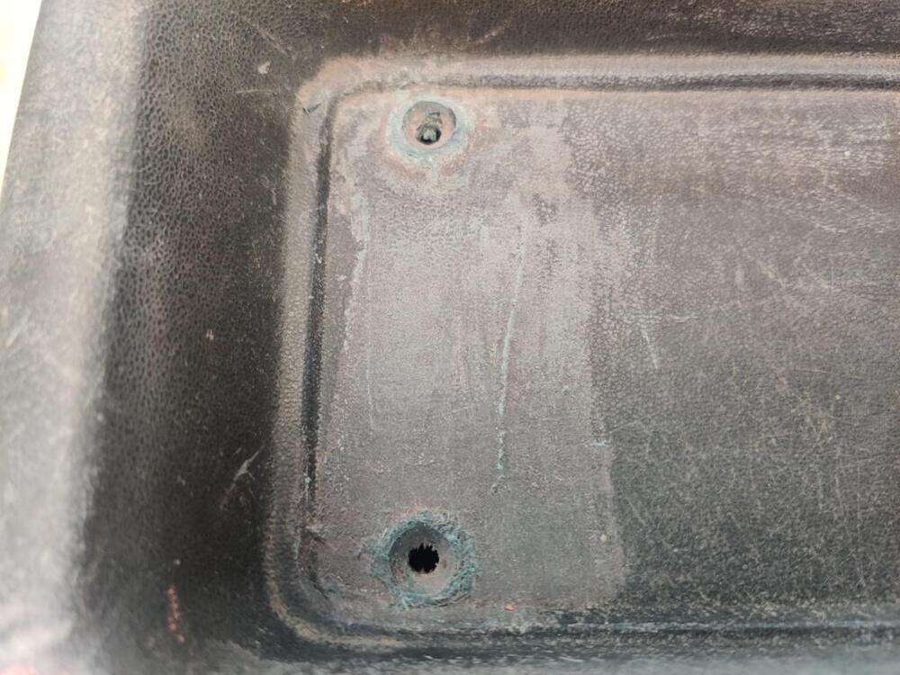
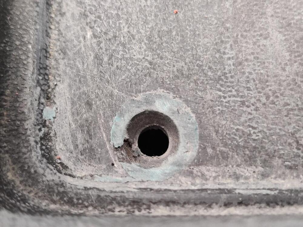
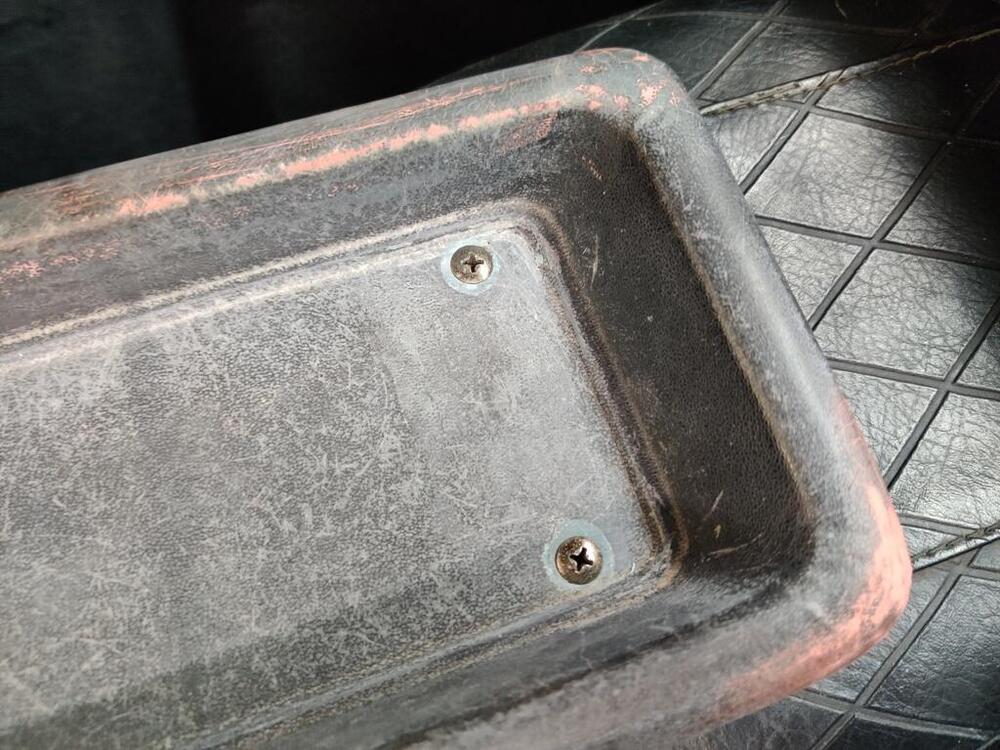
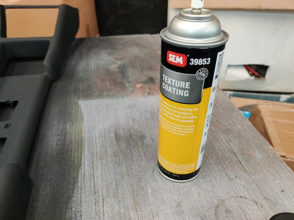
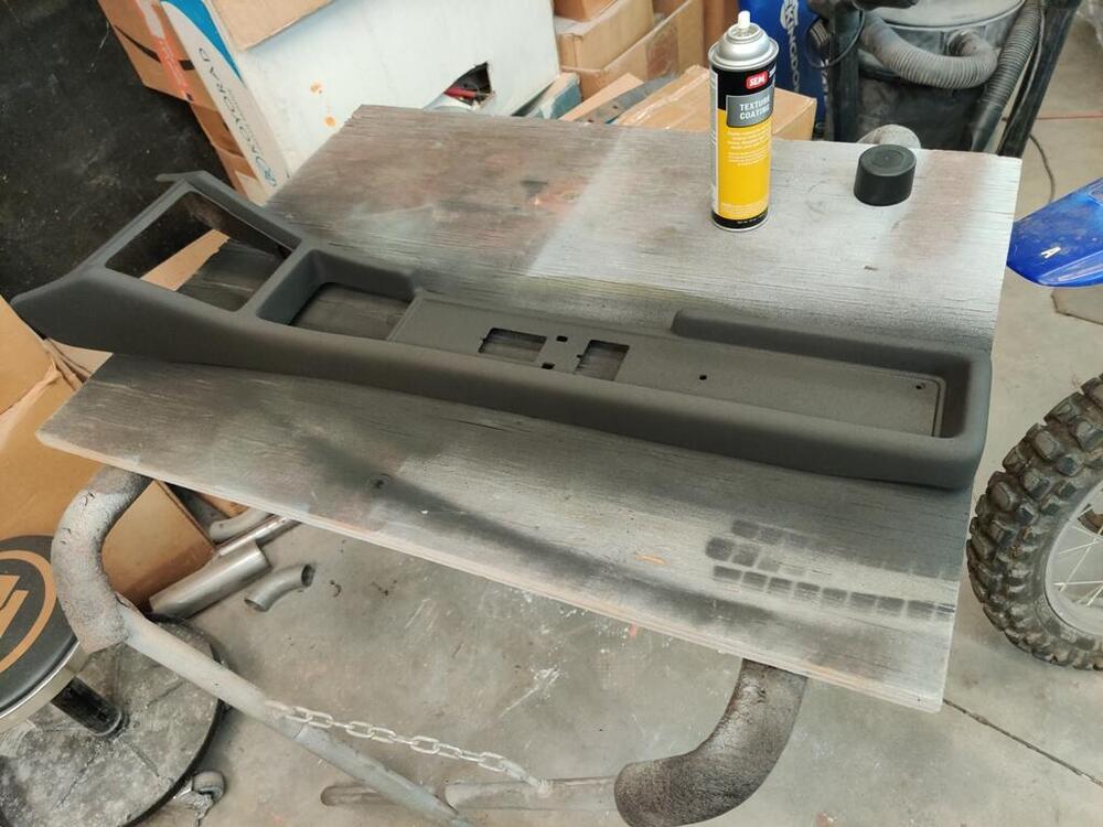
I continue to attempt to make progress. I was able to get in touch with the place that I had in mind to re-chrome the gas door knob and the ash tray parts. For the gas door knob (two parts) and two sets of ash tray parts (grill, plate and cigarette lighter trim ring - 3 parts X 2), they quoted between $200 and $300. I have been working on restoring the center console this week. The plastic trim plate had a crack in it. I was able to swap the one from my track car. I cleaned it up and used a "chrome" paint pen to return it to how it looked originally. The two rear-most mounting holes in the console were oversize, allowing the screws to slip through those openings. Thus the screws were not securing the console to the car. The console is fiberglass. So, I ground away as small amount of material on the underside. Then I mixed up some resin and hardener and put some fiberglass mat pieces in place to rebuild the part around the holes that had broken away. As the resin was hardening, I drilled new holes. Drilling is easier when the hardener is not fully hard and I feel I can control the location of the hole better. After the hole had been drilled in the fiberglass mat, I mixed up a small amount of fiberglass/polyester filler and applied that to the topside surface. While it was still unhardened, I installed the screws. They have a tapered head. I let them sit until the hardener kicked off, but removed them before the fiberglass filler fully cured (third pic here). In these pics, you can see the ring of filler around the holes after sanding the small amount of fiberglass filler applied on the top side. I used a counter sink bit in a drill to open these up a bit further, however, the factory recesses around the bolts were a bit larger than what I ended up with. The console had many cracks in the surface. To address those, I sanded with 80 grit first, then switched to 240 grit. Instead of using polyester filler, I used glazing spot putty. Sanding this is much easier. The benefit is that when sanding, it is easier to keep from sanding the original part. With polyester filler being much harder, as you try to sand it flat, you end up sanding the core part a lot more, ending up with more surface unevenness. After sanding and prepping the surface, I sprayed SEM texture coating 39853 on the surface of the console. Varying spray distance, you can end up with different textures. After this dries, I plan to use 800 grit sanding pads to "flatten" the texture I have here: Hopefully that will look reasonably close to the original factory finish. The final step will be to paint the console with a semi-flat black paint.


-
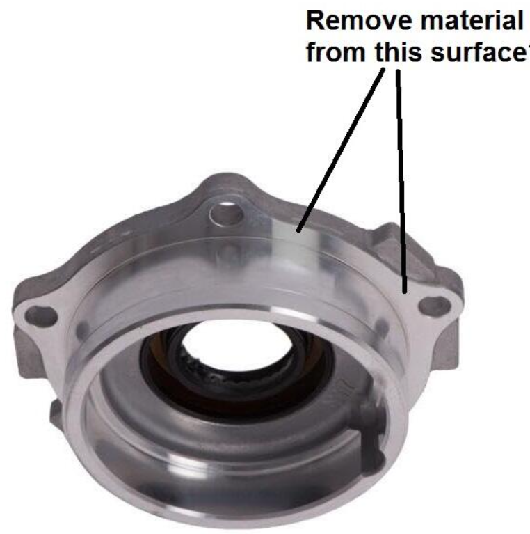
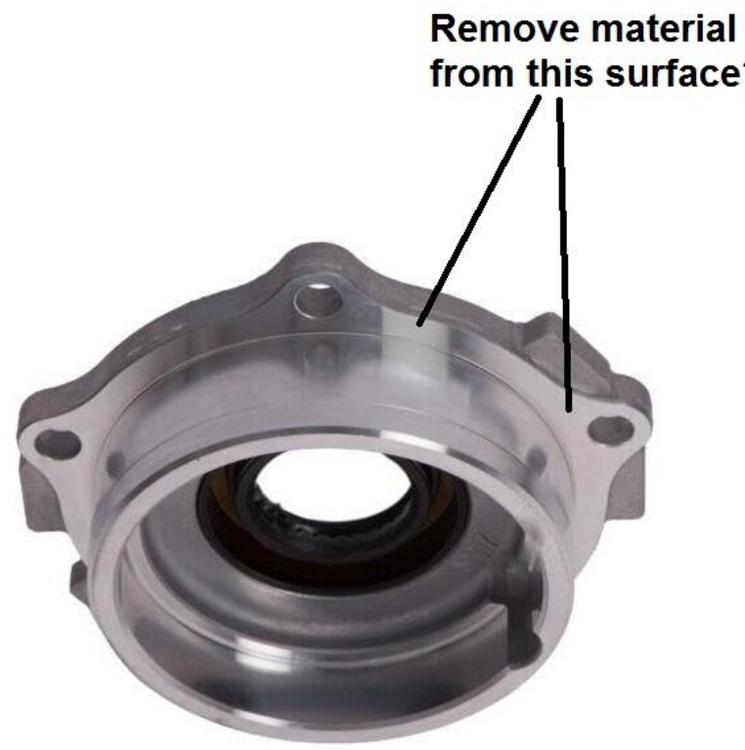
Update time. I put the stock pinion spacer/shim back in and took a fresh set of wipe patterns. These wipe patterns look "better" to me in that the amount of surface area where the paint has been "cleared" is much larger that what I was achieving by adding thickness at the pinion spacer/shim location. This time I put drag on the crown wheel as a rotated the assembly to get the marks. With the .3 mm shim on the left side bearing and the .4 mm and .5 mm shims stacked on the right side bearing, I measured .021" plus some of backlash. The pattern above was with that combination. I moved the .3 mm shim to the right side and measured backlash again. This time it was .012". I somehow forgot to get a wipe pattern after doing so. I will do that and take some more pics and post them here. With less backlash, the wipe mark should move further away from the heel end and toward the toe end (on the drive side of the tooth). With no more shims to move from the left to the right, the best way I can think of to less the backlash is to machine the left side bearing retainer. A picture: Removing material from this face will result a change to the the carrier bearing location vs. where it sits now when the flange is bolted to the case. So, to fix the excessive back lash, I want to shift the carrier to the right some small number of thousandths of an inch and I want to achieve this by removing a small amount of material from the left side flange. Doing that will bring the ring gear closer to the pinion gear. Additionally, whatever amount is removed from this retainer has to be matched in additional shim thickness on the right side bearing retainer so that the preload on the carrier bearings does not change. As originally assembled with the original carrier, there was a .3 mm (0.0118") on the left and a .4 mm (0.0157") and a .5 mm (0.0197") on the right. That combination adds up 1.2 mm. Side shims are sold in the following mm sizes: .2, .25, .3, .4 .5. If, for example, I estimate I can get the backlash within specification by removing .2 mm = 0.00787" from the left side flange, then that amount would be removed from the left side flange and I would add a .2 mm shim to the existing stack of shims on the right. Or, another option which would achieve the same thing would be to machine .5 mm off of the left retainer, and then add a .3 mm shim to the left side and a .2 mm shim to the shims already on the right side (add .2 mm more to the .3 mm, .4 mm, and .5 mm shims). Again, whatever the amount that gets machined off of the left side retainer, I will need to add back into the total shim thickness. Ultimately, I need to get backlash to .004"-.008". It may be best to remove .5 mm from the left side retainer because then I have many sizes of shims to work with from an adjustment standpoint. Also, removing .5 mm covers the possibility that I run into a problem of removing .2 mm and that not being enough to get the backlash to .008" or below.


-
Congrats! I like the color choice too.
-
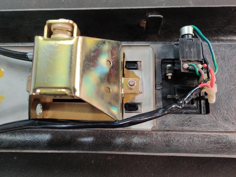
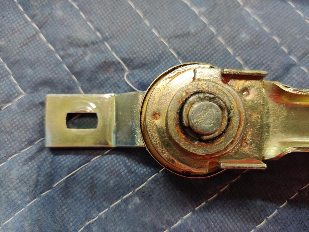
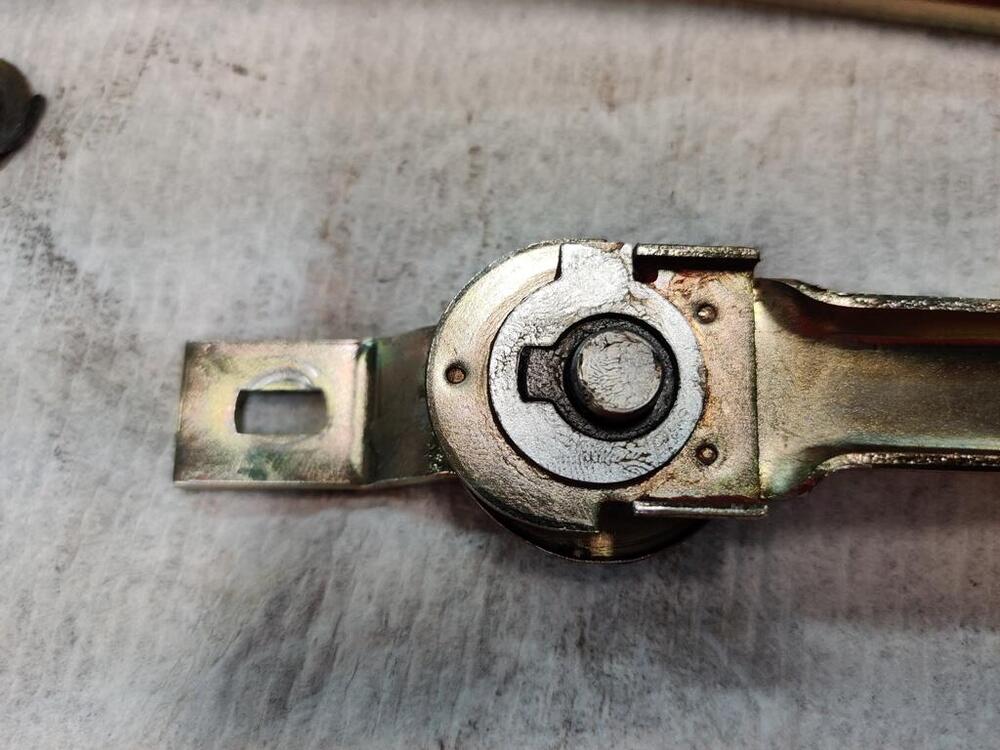
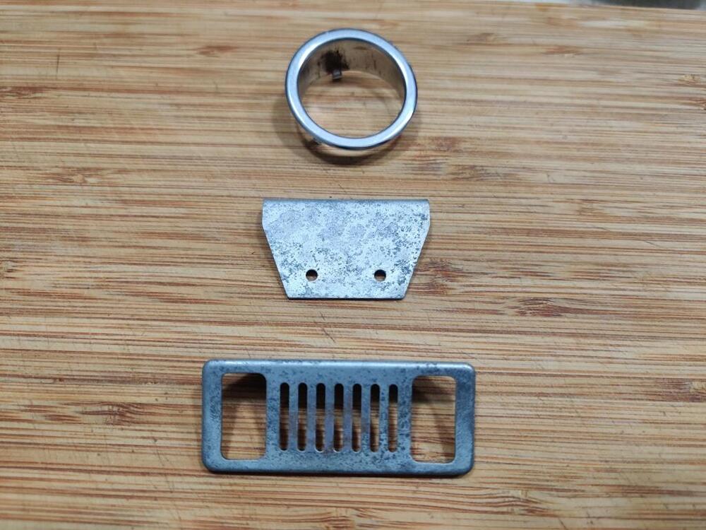
From my list: Machine shop to remove a small amount of material from the left side flange of the differential - need to put the stock pinion shim back in and then check back lash with original side shims in their respective places. Then check backlash again after moving the one left shim to the right side. Compare the difference and estimate amount to have removed from left side flange, given side shim sizes available. Send driveshaft off for balancing, but... I have to put the differential in car and check drive shaft fit first. I may need to remove some of the shielding on either the rear of the transmission or the driveshaft. Tell Snake Oyl to proceed with the restoration of the seat belts I sent them in June even if reproduction date tags cannot be sourced (they have delayed for weeks because they haven't been able to confirm that they can get the tags from "their vendor". They will be able to get the labels. Cashier's check and additional parts are going out via UPS to them tomorrow. Buy carpet in bulk (still have to decide which). Cut to fit the car and have local company put correct finished edging. Or, purchase Auto Custom Carpets, Inc. kit from RockAuto. I may purchase this kit for day to day use... and have a custom set of carpets for show. I Purchased an Essex pile version of the carpet set available from ACC (Auto Custom Carpets) https://www.rockauto.com/en/moreinfo.php?pk=6070062&cc=1209158&pt=1264&jsn=10419&optionchoice=1-A1168-0-1 Get gas door lock and ash tray grill chrome plated by local company - email with pictures of parts needing to be re-chromed sent to get quote Horns - these have to be re-plated before I can put them back together I also have the following fairly large lift items: Assemble the seats - fit new support straps, foam and upholstery covers. Repair/restore center console Test gas tank for leaks - source and install a new tank from S30 World if it leaks Find source of the electrical short circuit in the windshield wiper circuit Found it with @SteveJ help. So, some progress, but it still looks like I am going to run out of time to me. My windshield wipers were not parking as they should. They were parking higher than their range of sweep. That is not right. They are supposed to have a range of sweep that is higher than the park position. After reading related posts, I realized that I had not paid attention to the reassembly of some of the parts on the wiper linkage. In order for the linkage to park lower, the offset cam piece in the wiper linkage has to be in the position to make the linkage arm longer. Some pics: As found with the issue: cam/offset in the short position: cam/offset in the long position (note that you can see the edge of the of the back plate, and the linkage bar that attaches to the motor is extended to the left a bit more: After removing the clip and the top washer: After flipping the cam/washer piece with tang over - now with the tang at the top position, the link bar is in it's shorter length position. So the pic just above is CORRECT. This is the position of the washer with the tang when the motor is operating. When the motor reverses, the offset and tang will rotate 180 degrees. This will move the link bar to the "long" position which will extend the effective length of this arm just a touch. And it will result in a park position on the windshield where the wipers will be lower on the windshield than the normal sweep range. Also, I found that the best park position was set when the link bar (the piece that bolts to the back of the wiper motor shaft is in alignment as in these pictures. In other words, the ideal park position is achieved when the link bar is in perfect alignment with the long linkage bar it is attached to. Like this ------ -------. Not angled either up or down from the long bar, but simply a linear extension. I had to install the motor with the bag hanging off to the side so I could mess with the round cap on top of the motor that adjusts final resting location of the motor shaft. Then remove the motor again, put the bag on and reinstall the motor.


-
Were these clear zinc plated originally, or chrome plated?
-
I called them today. It seems they had a place in Atlanta, but they said that during Co-vid they shut it down. They only have operations in CA now. I will send them pics and get a quote. This is the website: https://decometalfinishing.com/chrome-plating-in-atlanta-ga.html
-
I certainly could use the help. 🙂
-
I have been thinking of driving the car to ZCon in Tampa. I've made a list of things that need to done before the car is done and it is large. At this point, I am thinking I will not be able to finish in time. Here is a partial list, mostly of items requiring outside assistance: Machine shop to remove a small amount of material from the left side flange of the differential - need to put the stock pinion shim back in and then check back lash with original side shims in their respective places. Then check backlash again after moving the one left shim to the right side. Compare the difference and estimate amount to have removed from left side flange, given side shim sizes available. Send driveshaft off for balancing, but... I have to put the differential in car and check drive shaft fit first. I may need to remove some of the shielding on either the rear of the transmission or the driveshaft. Tell Snake Oyl to proceed with the restoration of the seat belts I sent them in June even if reproduction date tags cannot be sourced (they have delayed for weeks because they haven't been able to confirm that they can get the tags from "their vendor". Buy carpet in bulk (still have to decide which). Cut to fit the car and have local company put correct finished edging. Or, purchase Auto Custom Carpets, Inc. kit from RockAuto. I may purchase this kit for day to day use... and have a custom set of carpets for show. Get gas door lock and ash tray grill chrome plated by local company Horns - these have to be re-plated before I can put them back together I also have the following fairly large lift items: Assemble the seats - fit new support straps, foam and upholstery covers. Repair/restore center console Test gas tank for leaks - source and install a new tank from S30 World if it leaks Find source of the electrical short circuit in the windshield wiper circuit Then, there are the things I am forgetting... hahaha
-
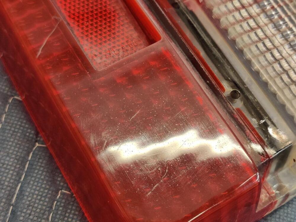
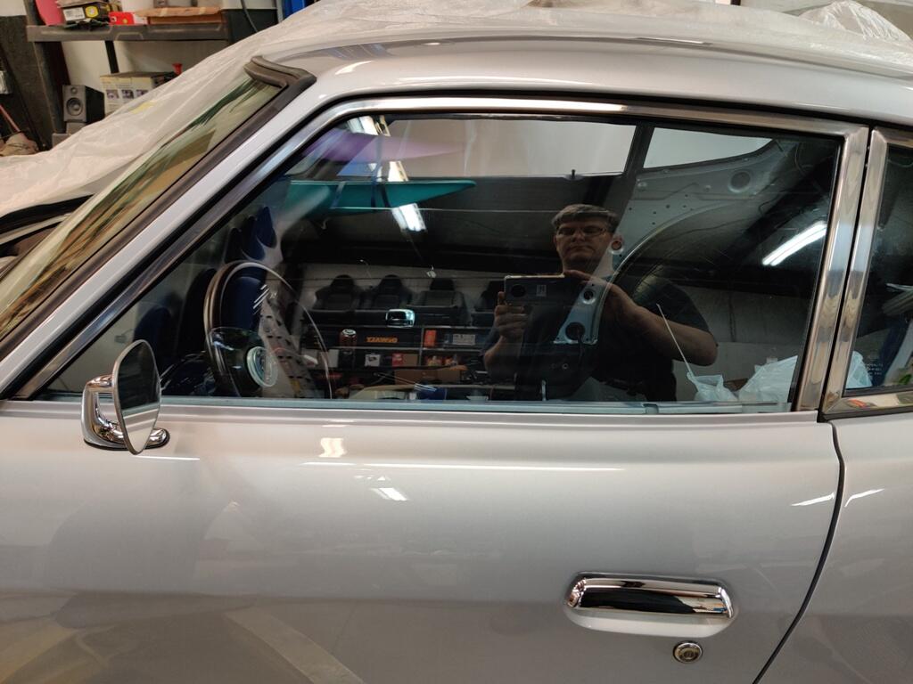
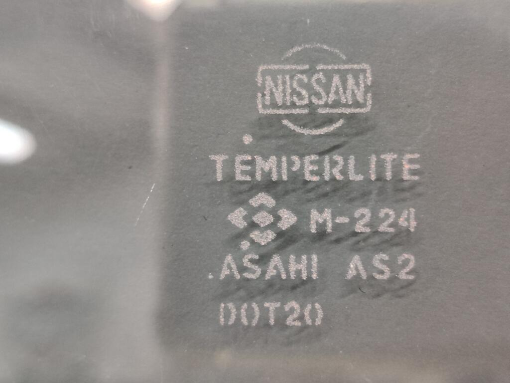
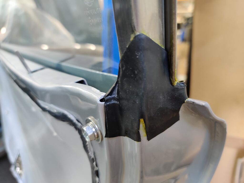
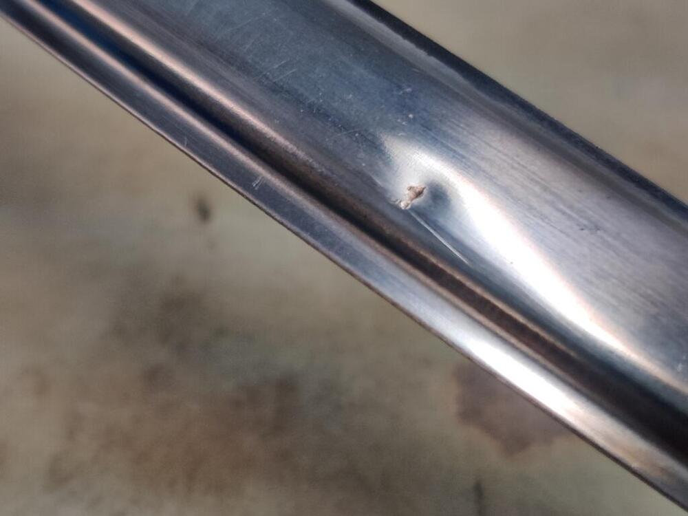
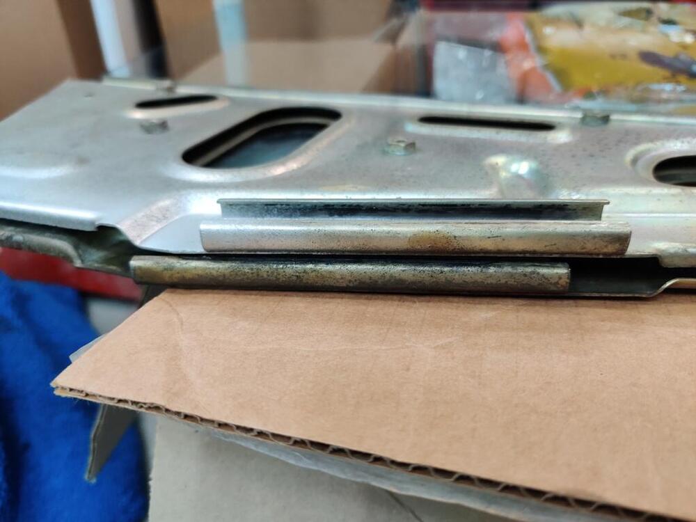
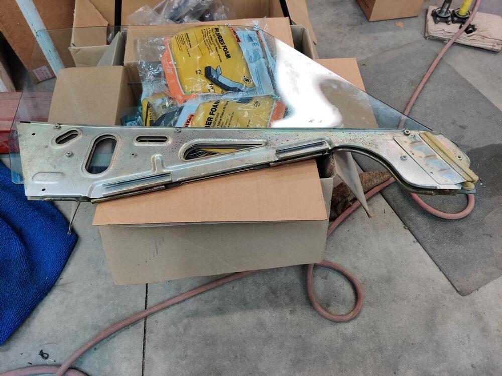
I didn't keep track of the hours closely, but I am going to say it took something around 10 hours of work to remove the scratches and restore the shine to the left door window. Thanks again to @Patcon for helping me source a left door glass with a date on it that is "in the ball park" for my 6/71 car. There were several deep scratches as well as some pitting which I was mostly successful at removing. I don't know if anyone else has the stomach for putting this much effort into removing scratches on glass, however, I think I should be honest in case future readers want to give it a try. The most aggressive disc in the kit is "a beast". It will quickly remove glass... and put nasty swirl marks in your glass in the process. Use it only if you have really deep scratches. The green discs (middle grit) are quite aggressive. Use these for light scratches and minor imperfections. The blue discs are quite fine. You will burn through them at a pace of 5 to 1 vs. the green discs. It is hard to see when you have sufficiently polished out the scratches from the green discs. Attack the glass at a 90 degree angle from when you use the green disc. It will be easier to see when you have removed those scratches if you do this. This https://glasspolishshop.com/polishing-repair-compounds/cerium-oxide is effective at polishing the glass back to a good amount of clarity and shine. If found that the Eastwood polishing buff was better than the polishing pad that was included in the pro polishing kit I bought: https://glasspolishshop.com/glass-restoration/scratched-glass-repair-kits/pro-glass-scratch-removal-kit-xnet-system. I think the Eastwood felt buff was harder than the one received in the kit. And using it, I believe the cerium oxide was utilized more effectively on the glass. With a softer pad, I think the cerium oxide was not pushed as hard against the glass, and therefore, did not polish as effectively. After so many hours of neck wrenching work, the scratches have been removed from the glass (except those very close to the Temperlte etching). When sighting down the glass at a sharp angle, you will be able to see slight waves or undulations. The finished product looks a bit like bodywork that was not done perfectly. Glass does get removed after all, and because it is so hard relative to primer or filler on a car body, it is exceedingly difficult to remove scratches and keep the glass perfectly flat. Anyway, there it is - the info you would like to have about attempting to remove scratches from glass. It takes a lot of effort, many hours, and though the final result may remove deep scratches, the final result will leave you with some slight waviness in the glass, and not the same level of smoothness as the factory finish. In other news, the window support is different from the 1971 vs. 1975 cars. Here are a few pictures which show that the regulator channels are in different locations. This makes using a 75 window in a 71 car not work. After I finished work on the left door glass, I installed it in its frame/support and installed it in the left door. Order of operations is: Install stainless steel frame (with glass channel weather strip already installed. Then window glass. Then front glass glide. Then regulator. Then rear lower guide for regulator wheel. After I confirmed rolling the window down and up was as it should be, I installed the 3M product for holding the vapor barrier in place. This product is very tacky. So, it sticks to the door, and the plastic vapor barrier to it, extremely well. Next, I will put the door panel clip receivers in place. I will need to cut the vapor barrier in a couple of places (around the window roller and the door release) and I will need to glue in place a couple of rubber seals before I can put the door panel on.


-
It is kind of freaky how you and I are traveling in parallel on so many Z restoration things. "I finally received this PVC tubing the other day. I bought it for the front markers lights but realized I needed a piece for the wiper motor too." - I bought some from Amazon just the other day for my from side markers. I went with the 1/4" diameter instead of the 3/8". I will be ready with the lacquer thinner when it is time to install it. "I can't upload the picture I want, but I the plug on the wiper was bad and instead of depinning it, I crushed it with a set of channel locks. Much faster!" - I did the same with one of the connectors for the steering column wires. It seems that the harness connectors are made out of a plastic which is not UV resistant. Sunlight makes them turn yellow in short order. I used Vise grips to bust mine to pieces. "I replaced the pins on the end of the wiring. Put a new jacket on the cable and reinstalled the wiper motor and bracket into the car using Steve Nixon's great little rubber pieces" - Same here. I seem to have an electrical issue with mine though. I tested the motor the other day and it kept running when I turned the wiper switch off. The fuse for the circuit blew shortly there after. I replaced the fuse and it blue again within seconds. Looks like others have beat me to the punch on the round head wiper screw. G
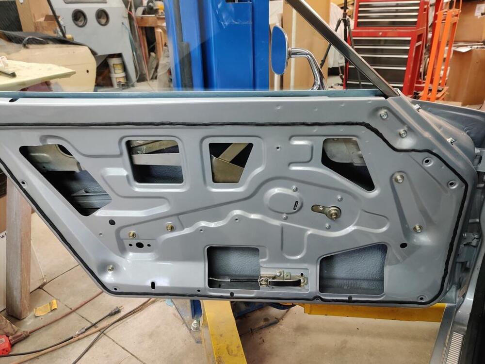
-
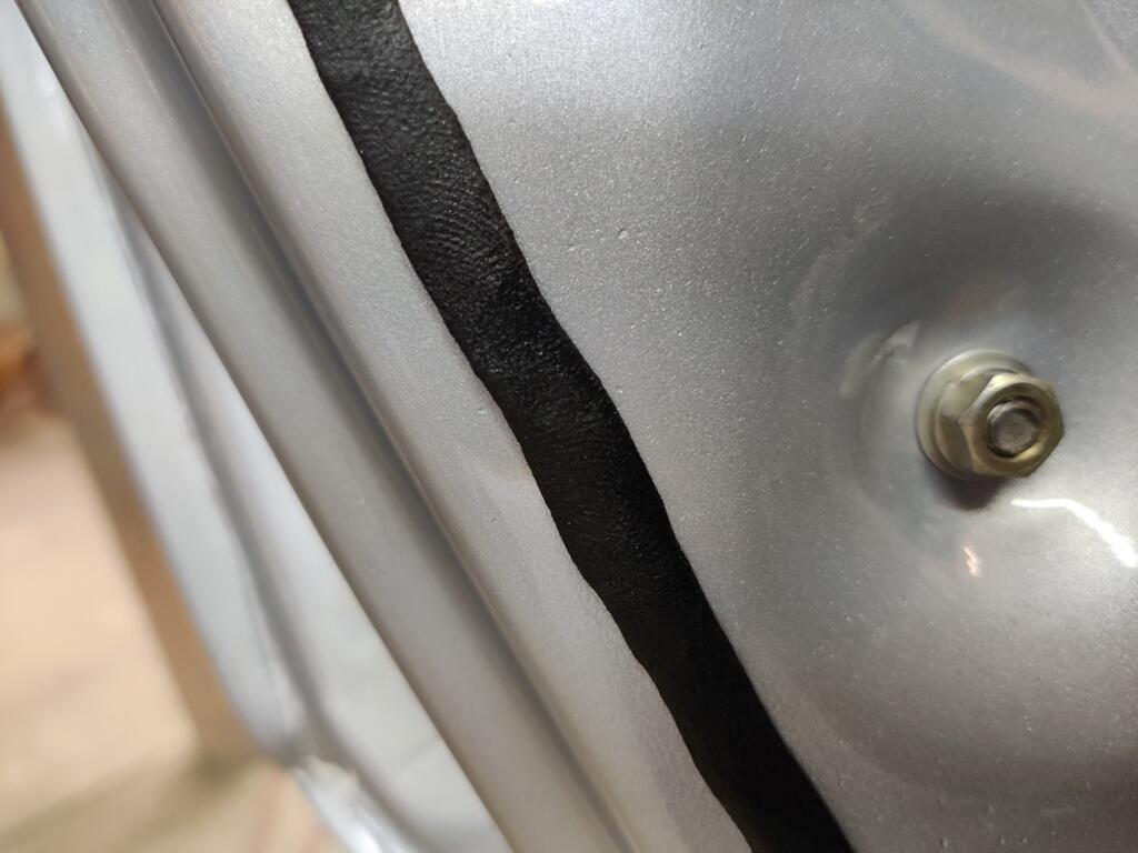
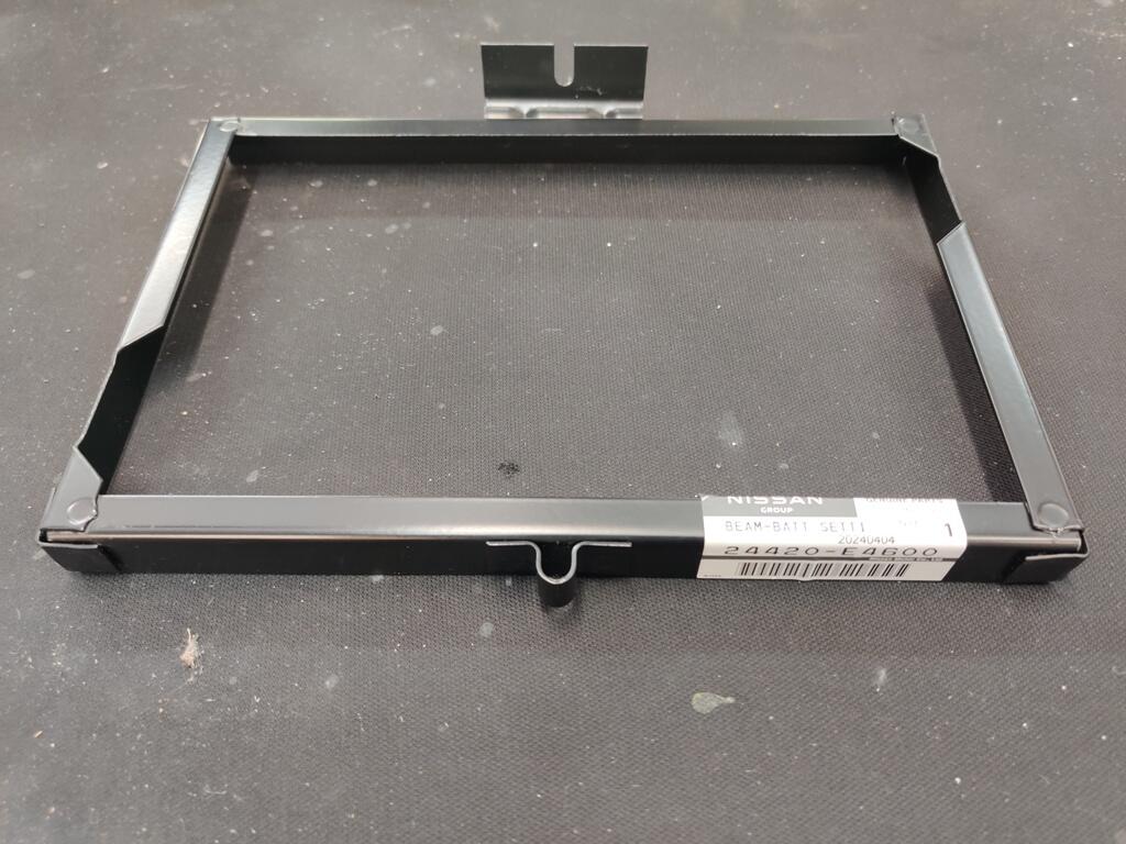
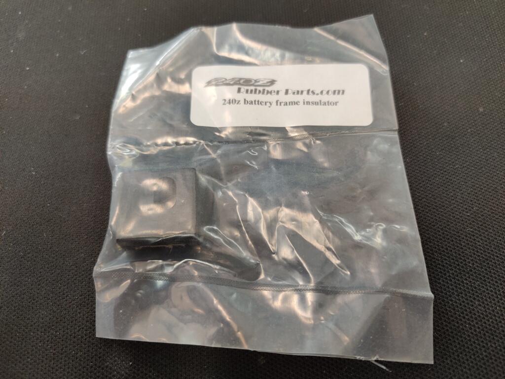
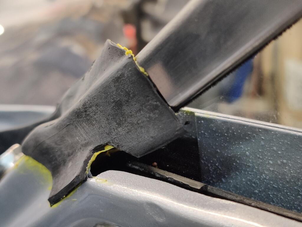
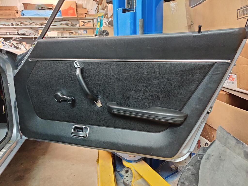
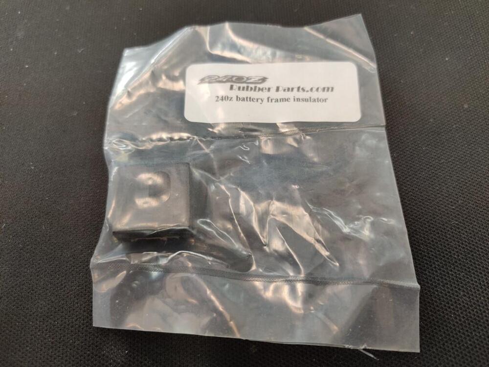
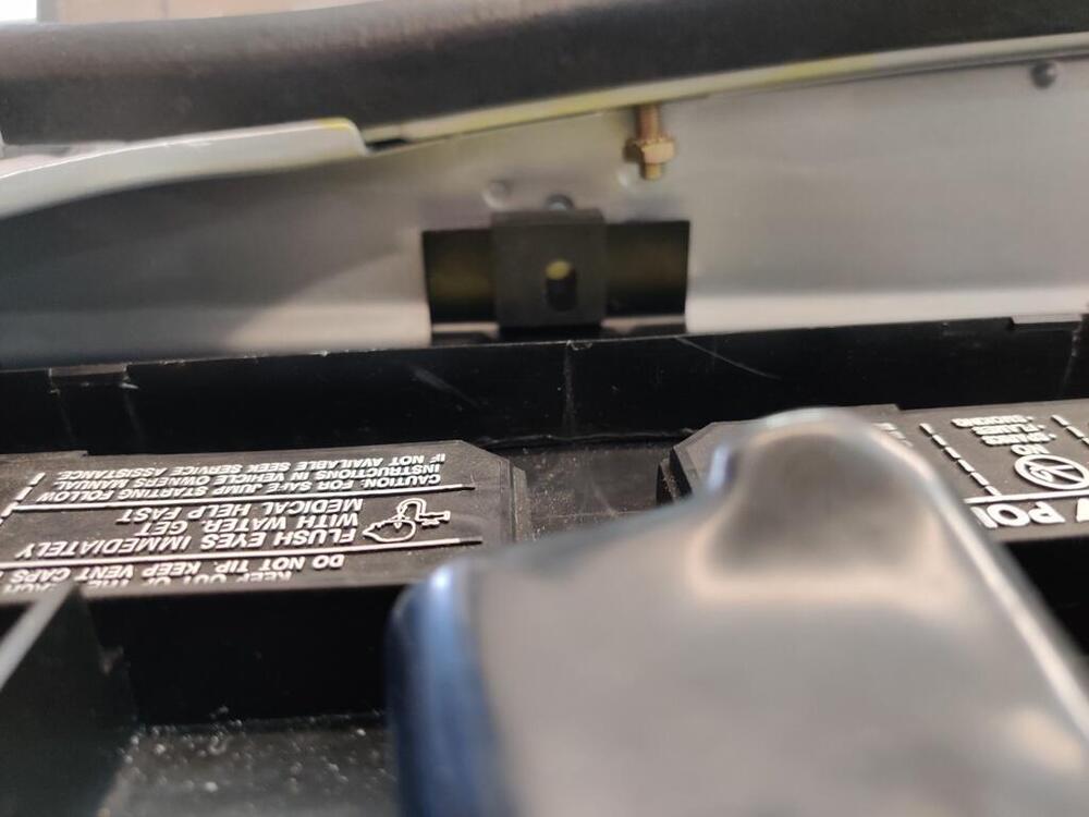
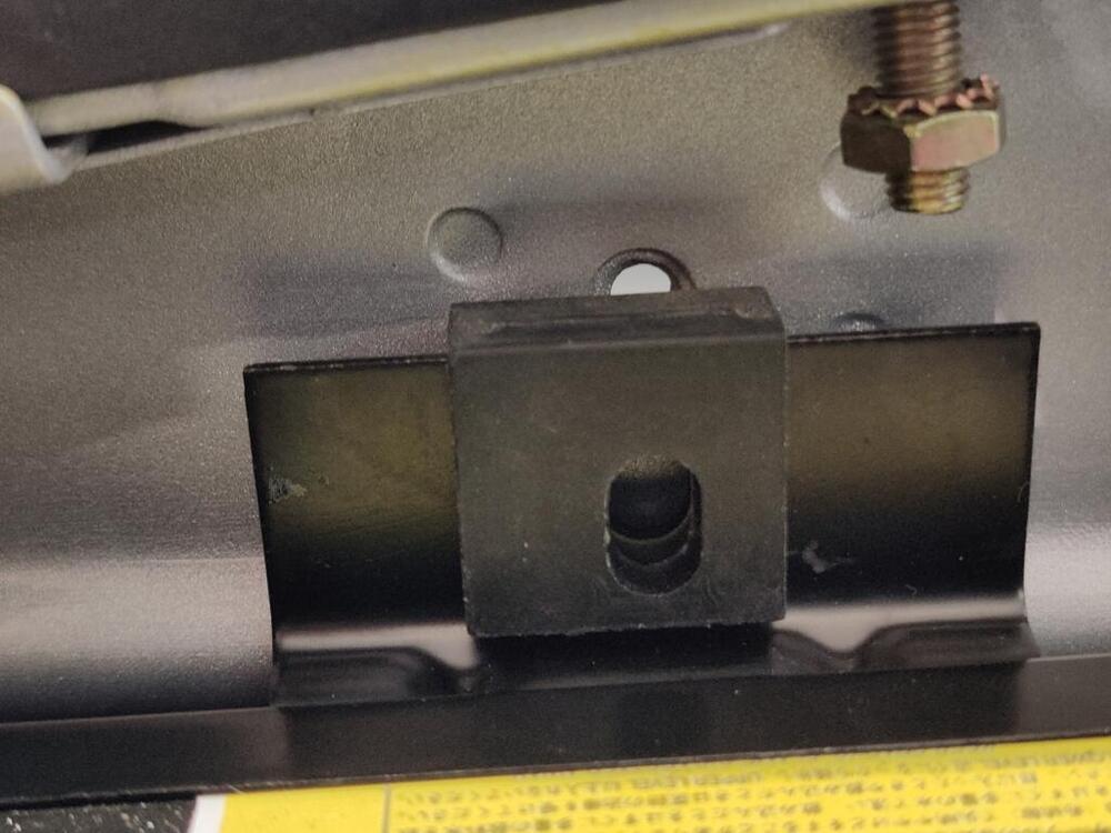
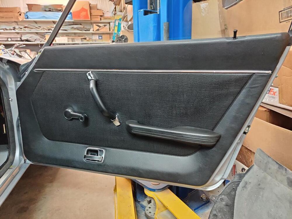
Lately, everything I attempt to do on this car fights back. For example, I have sourced a new battery, battery tray, and battery frame from a Nissan dealer. So, with all these "factory original" parts, how do I end up in this situation? A closer look: Is this battery shorter than the original? Is the battery tray thinner/shorter than the original? A combination? When I saw this, I just laughed and walked away to do something else. I am also wondering why the slot in the rubber part here is offset to one side. I have no clue. Next came more work on the right side door. I am still dealing with the consequences of the paint shop removing the doors (and I specifically said not to). Getting the right side door aligned exactly the way it was is a pain in the arse. Tightening the hinge locating bolts, loosening... rinse, repeat. I had them where they belong and did final body work finishing across the door gaps. I had it really close to perfect. Now, I am struggling. The door is made of thin metal. It is quite possible that by the time you bolt in the stainless steel window frame and put in the regulator and the glass, the shape of the door changes a bit. Probably a key piece of helpful info for those of you reading this and yet to apply paint to your car in the future. After quite a bit of fiddling, I got the "feel" of rolling the window up and down right - consistent slight amount of force throughout the travel both downwards and upwards. Next, I made a vapor barrier for the door and put that in place (sorry, no pics - I will remember when I do the left side). I had to straighten the lock pull rods as they were a bit "bent". The product I used to attach the vapor barrier to the door (first pic of three), and new door frame seals: For the front door frame seal, I couldn't get my favorite contact adhesive to stick to it properly until the third try. After the first two, I scuff sanded it. Only then did the adhesive stick to it properly. I have some adhesive clean up to do still. After these seals were glued into place, I could put the inner door panel on. I sourced reproduction door panels some time ago, probably a couple of years. They appear to be good quality, but I decided to move the door panels from my track car to this car. I purchased these new from a Nissan dealer around 1994. They are still in very good condition. The track car will get the repro panels. Getting the pull strap on took a crazy amount of time and effort. The chrome pieces do not want to snap into place. I had to massage and modify a bit here and there until they would finally latch into place. Anyway, that is how it can go sometimes. Much more difficult than it should be. But, I press onwards. 😉


-
I did, including the glove box lock. For that one, you have to drive out a pin to access the wafers.
-
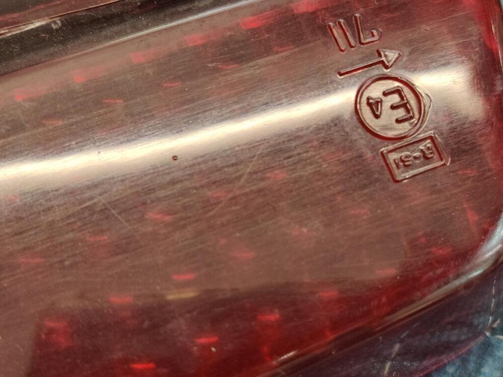
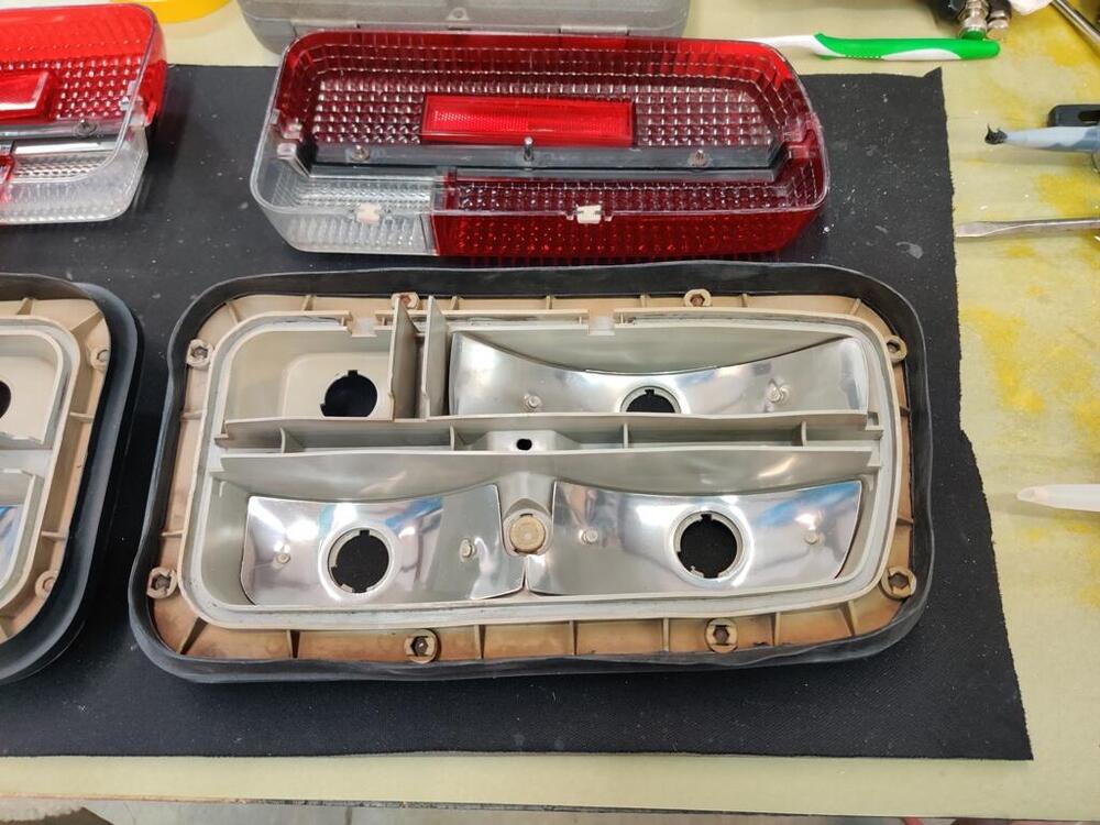
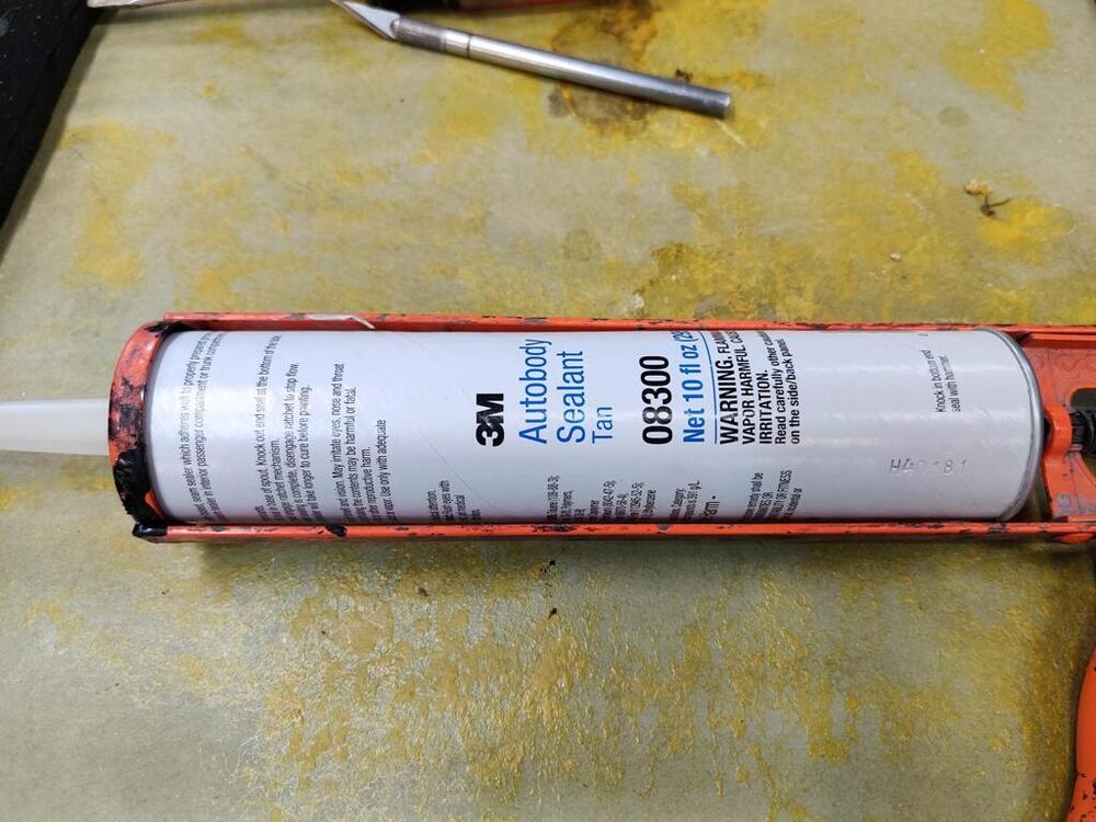
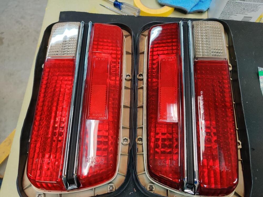
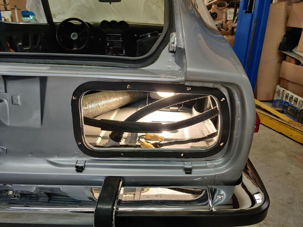
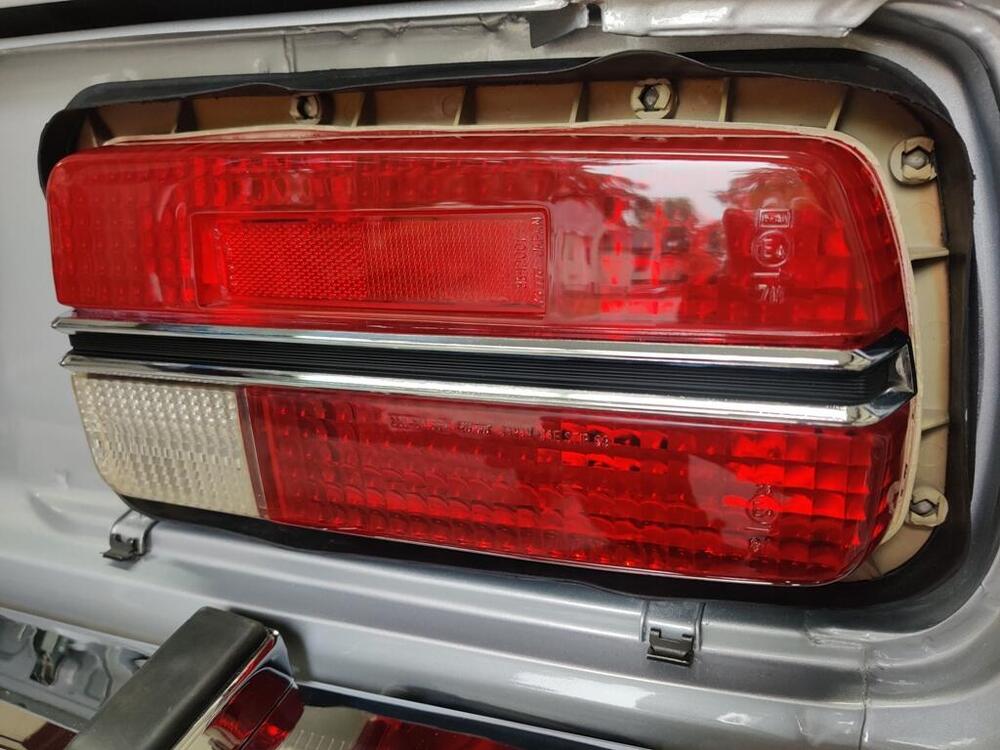
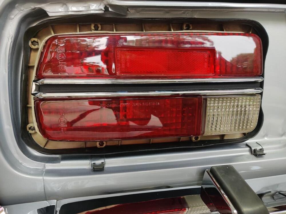
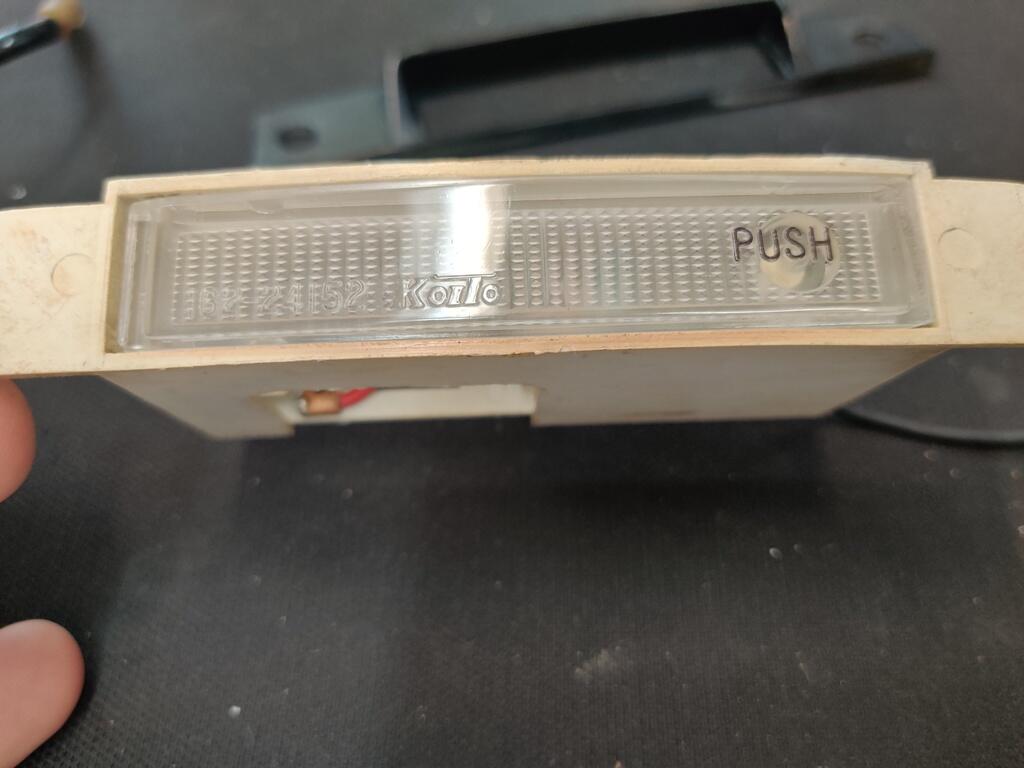
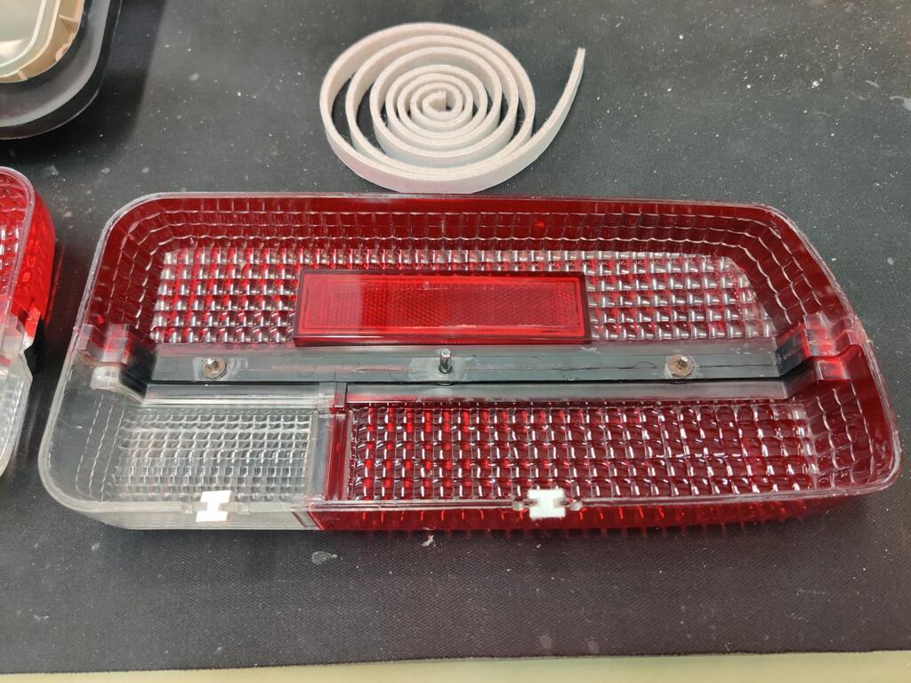
Correct, the tower and smaller rear wheel well are covered by one piece first. Then, you put on a second piece that covers the front wheel well. The "riser", behind the seats is installed last. Yesterday and today I worked on removing scratches from the replacement left door glass I got from @Patcon. I had to order some more discs and powder, so I set it aside for now. I went to install my tail lights and upon close inspection, determined that one of them needed more sanding and polishing to restore the proper shine to the lenses. After some more effort was expended there, I was able to glue the lenses onto the housings. For that job, I used auto body seam sealer. Seems like and odd thing to use, right? But, the old stuff that I removed from the housings when I pulled the lenses off looked like seam sealer. And, I had good luck with using it once before on the tail lights on my other 240z. My tail light lenses were in rough shape to start. Lots of pitting and scratches, some of them deep. I bought a small roll of felt from Home Depot and made little pieces to replace those that were originally in the bottom of the assemblies. I guess these are vents... to allow any moisture that finds its way into the assemblies to dry. While the housing were separate from the lenses, I used a heat gun to attempt to straighten the mounting flanges of the tail lights. These distort over time and prevent the stock rubber gaskets from sealing to the body of the car like they should. When "gluing" the lenses back to the assemblies, there is a need to use clamps (and boards and rags) to clamp the lenses to the housings, and let the sealant cure for 24 hours. Even with the housing flanges straightened somewhat, I used some self adhesive weather stripping (highly compressible) between the tail light assemblies and the body. These are now air tight - no exhaust fumes will be coming in through this notorious location. While not perfect, the lenses look very nice now.