EuroDat
Free Member
-
Joined
-
Last visited
Everything posted by EuroDat
-
 Im trying to remember what I did exactly. Unfortunatly I didn't take many photos and none when I was reverse flushing the injectors. I lot of crape came out of the injectors especially nr. 3 and 4. I didn't dismantle the dizzy or rotor button, but I can remember removing the coil HT lead from the dizzy and fitting it on an old spark plug and clamping the spark plug to the body on the strut tower. Just as a precaution not to overheat or damage the TIU etc. BTW: I also disconnected the lead to the Cold start injector so it would keep pumping fuel into the manifold. I used a 9 volt battery to activate the injectors when I was reverse flushing them. Read somewhere on an Alfa Romeo site that the injectors should not have continous 12 volts through the coil. They normally pulse which means an average voltage of about 8.5volts. I tested one with 12 and 9 volts and it flowed the same so 9 volts is playing it safe. It was a german website andI can't find it anymore. Chas
 -
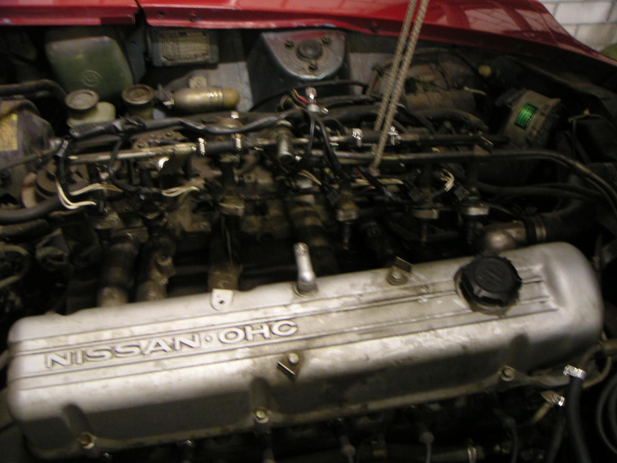
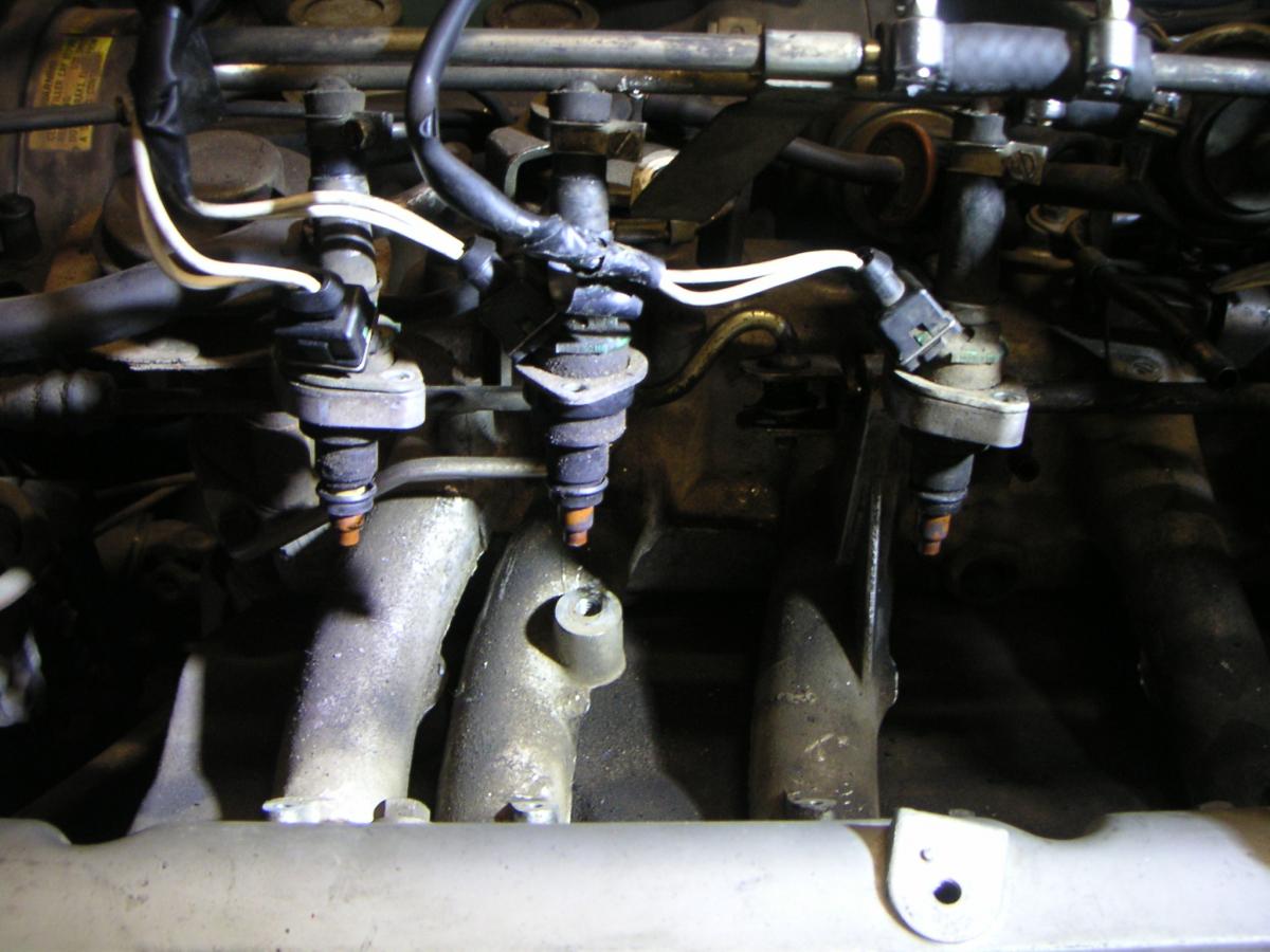
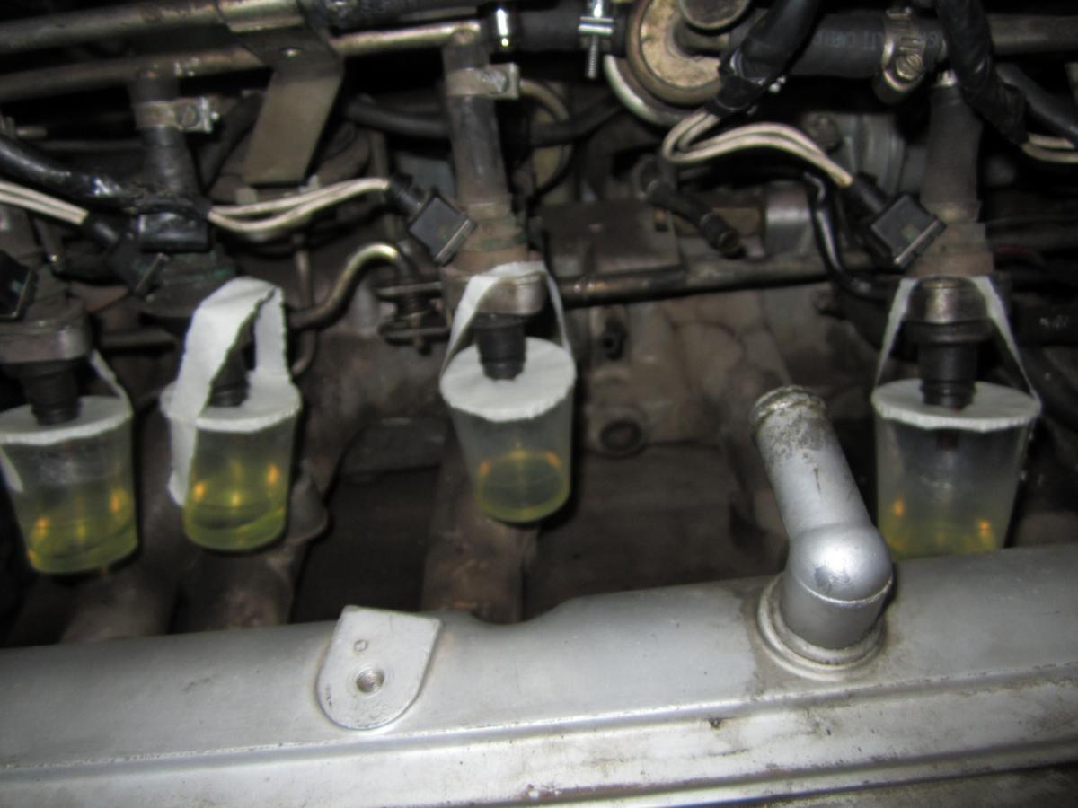
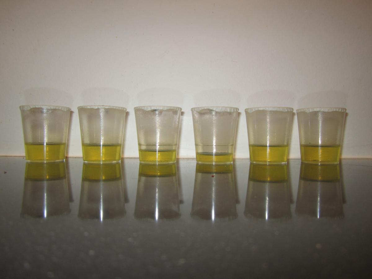
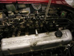
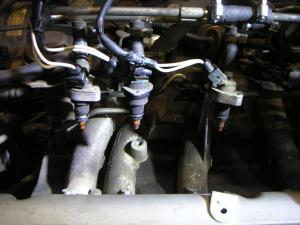
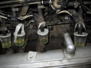
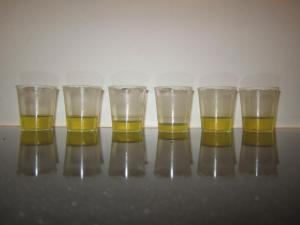
Hi Bob, Im a little late, but maybe it will help you a little. I had a problem with to lean cyclinders a couple of years back. I did a simple (ans I mean more crude than simple) test to see if the injectors were the problem. Basically I removed enough of the mounting fixtures so I could get the injectors and fuel rail up high enough to see the tips clearly. Then I found some plastic cups from a local store "Action" (what you could call a $2 dollar shop) and strapped them onto the injector tips. Removed the spark plugs, rigged the AFM open and cranked the engine for about 20seconds. I didn't go to long on the starter. Didn't want to burn it out. It was enough to see number 4 was amost blocked, number 3 partly and number 2 was maybe a small amount. See last photo: left nr 1 to right nr 6. After that I reverse flushed them with a long hose full of fuel mixed with injector cleaner, air compressor and a 9 volt battery to trigger the injector. Kept repeating the flush until they where all flowing ther same amount in a beaker. Good luck finding you problem. If you need more photo's or info let me know. Glad to help. Chas
-
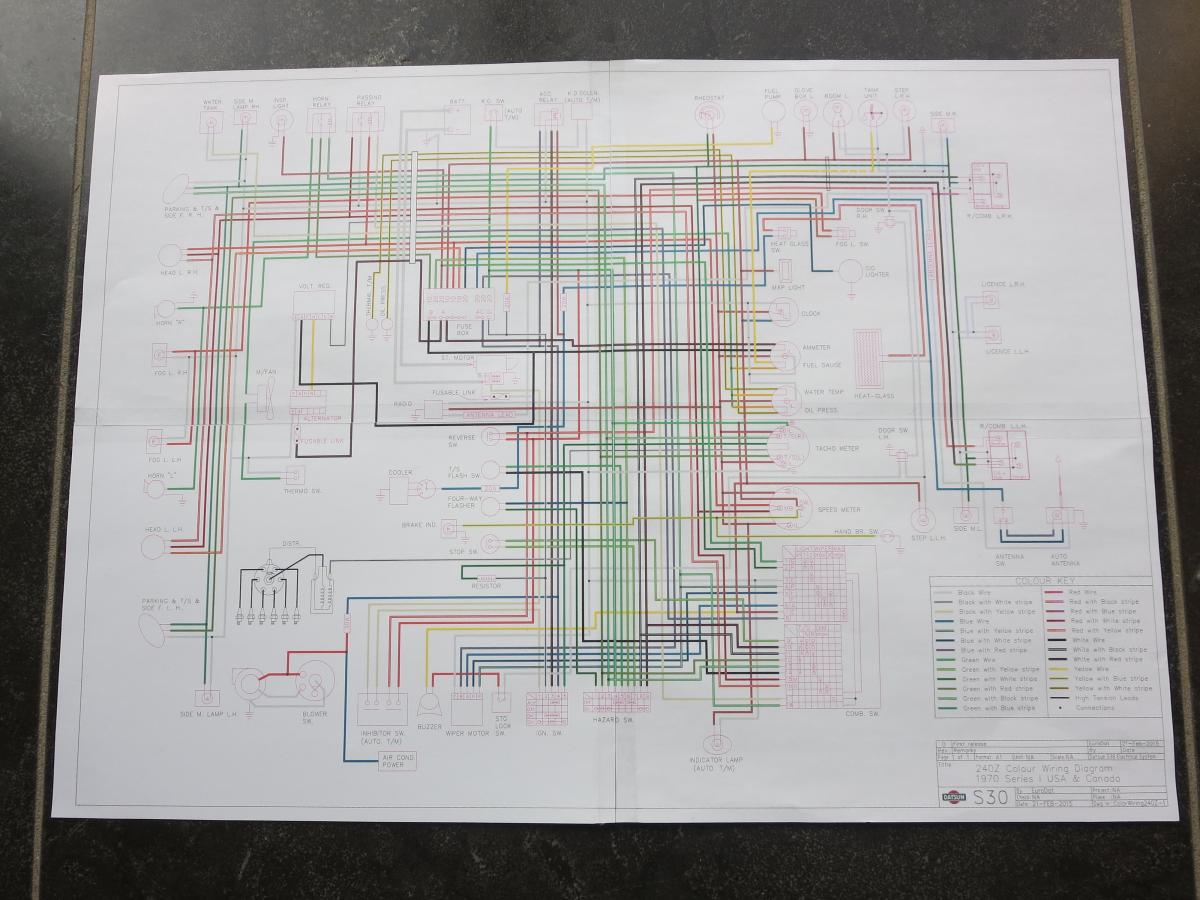
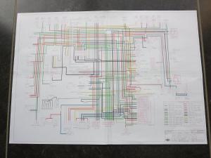
You might have already track it down, but if not here is a copy of the 260Z wiring diagram. It shows all the connectors and the wire colors are displayed so you can track down your connector that way. I think your connector will be in the top left hand corner of the diagram. This diagram came from http://www.xenonzcar.com/ if I recall correctly. It was more than 25MB when I downloaded it so I compressed it (basically removed all backward compatability) so you will need Adobe reader 9 or later. There is no loss is quality. Goodluck Chas 1974 Manual Electrical Diagram1.pdf
-
Thanks for the input. Blues idea of using the two other drawings and referencing would be an eas quick fix. I could easily add a table with wire size per connector. I imagine it would be handy for someone making a new harness. I was playing with the connectors on the wiring diagram, but it requires an aggresive reshuffling of the diagram to get them in. Specially around the instrument cluster and other dash components. I was trying to keep the original layout to give it a friendly firmiliar feel to it. That way if you have used the original this one will be easy to follow. Ill clean up the two illustrations and play with them tomorrow. Geezer, Do you know where I can find information on the wire sizes? Thanks Chas
-
Leuk, Een minnetje voor de koppeling. Ik heb de standaard koppeling altijd licht gevonden. Zeker als ik het vergelijk met andere sport autos.
-
Yes, you are right, I did mean the 280Z NA manual 1981 onwards. My mind was still in 71C mode. The 300ZX would work, but it would need the pinion flange from a 280.. R200. Since he has a 240Z with the R180 the 300ZX R200 seems pretty much pointless sourcing it.Chas
-
You can also use a 3.9 R200 (long nose) out of a 300ZX And the half shafts, tail shaft out and lower cross member (behind the diff) from a 280Z. The R200 would be the cheapest And will cost around $500. The STi will be a lot more expensive. Just the Wolf creek half shafts and odd bits and pieces will set you back more than $500. Chris did the R200 changeover on his 240Z. See post #11. He could give you some pointers if you choose that route. There is also a good thread hear on doing the STi (LSD) diff swap. Chas
-
Hi Zed Head, You might be thinking of the FS5W63A out of the early 1977-79 200SX. It was also an option on the 710. It was available in L and Z bellhousings. I think the 710 had the flange on the output shaft from what I can remember. I have read about it, but never seen one out of a 710. A long time ago I worked for a company that had a fleet of 710 and 720 dual cabs. Only two of the 8 710's had this box. Loved the 4th to 5th straight through. Shiftpattern. R 2 4 1 3 5 The 63 is the distance between the shafts. Its regarded as a weak alternatief and can barely handle an L20B. Ratios: 1st: 3.382 2nd: 2.013 3rd: 1.312 4th: 1.000 5th: 0.854 Rev: 3.570 Chas.
-
Hi Bart, Yes, You are right. That is why a said "common versions". The FS5C71A is getting hard to find in any condition. The next problem. The FS5C71A was not exported to the US or Canada in the 240Z It was in Europe, Australia, NZ etc. Its sometimes referred to as the Raoster swap in the US because they source them from the roasters, if they can find them in usable condition. I think you need the 240Z (Series I) F4W71A bellhousing to fit the roadster transmission to the L series engine. I have only read about one guy doing it. The 280Z and 280ZX both had 5 speeds. Up to 1980 they had a wide ratio version and after that they had two (fifth slightly different ratio) close ratio 5 speeds. The close ratio is a good transmission, but you should strongly consider changing the a 3.7 or 3.9 diff ratio. Otherwise first is too high. Chas
-
You have basically two common versions to choose from: The types FS5W71B & FS5W71C. The C will require some modification and you will need your 4 speed bell housing to fit it to the L24 engine. The 71B will be easier to fit and the transmission doesn't need modification. There are quiet a few varieties of FS5W71C transmissions to choose from. The 1984 300ZX came with 18mm gears. The 1985 300ZX onwards all had 20mm gears. Nissan introduced a mainshaft brake mechanism and wierd selector mechanism on the 1987 300ZX. Its also in the 200SX. Finally the double cone synchro was introduced in 1988 which is also the last year the 71C was used in the 300ZX (I believe). The S13/14 (200SX & 240SX) went through a similar evolution. I think the 71C was used through to 1998, but not certain of that. Somewhere around 1994 they introduced the reverse synchro. The 71C was also made with a stubby extension used in the Nissan D21 pickups until 1997 using the Z24 and KA24E engines. The rear extension was about 150mm shorter. It won't fit a 240Z without doing a lot of work to the tunnel and centre console. The FS5W71C was last used in the Xterra until somewhere around 2002.
-
I was thinking along those lines too. It would keep the diagram uncluttered and still easy to follow. The single bullets and Spade terminals could be added directly to the diagram. I started playing with it already. I also expanded the collection to cover the following: 1: 1970 to Early 1971. 2: Late 1971 to Early 1972 3: 1972 4: Work in progress 1972 Euro/JDM (With rear speakers and Rear separateT/S light) 5: Work in progress 1973 USA (With Seatbelt buzzer) The years (Timeline) may not be correct. Correction welcome. ColorWiring240Z1972USA_Rev_0 24-feb-2015.pdf ColorWiring240Z1971Late_Rev_0 23-feb-2015.pdf

-
The exhaust increased size when they went to the L26 (33 to 35mm). The inlets increased size (42 to 44mm) when they went to the L28 with the bigger bore diameter. Edit: You would think the inlets would be the problem, but I have since read the exhaust are the problem with a high lift cam. Chas
-
Holy crape. How did I not see that.
-
Ill check it with the 1971 supplement. Do you have any hints to start with? Most diagrams just have a retangle with the two wires going to it. I tried to make it look a little more realistic based on my knoledge of the 280Z system. Thanks for the input, I found a fault in the relay and corrected it. It looks right now, I think. Played with the print format today. I made two PDF's One in A1 format and the other is 4 pages in A4. If you print them you can trim them and stick them toegether to make an A2 format diagram. This way it can be printed at home at minimal costs which should suit the datsun crowd The files have been converted to Acrobat 9.0 and higher to reduce file size. Any misstakes, please let me know. No point making it if its not correct. Chas ColorWiring240Z1971_Rev_0 21-feb-2015.pdf ColorWiring240Z1971_Rev_0_A4_21-feb-2015.pdf
-
Chickenman. You are right. Thats mentioned in the tweak on Atlanticz although its not detailed. Mine was already lean so I calibrated the AFM according to the techtips on Atlanticz and I ran the potentiometer to the center console so I could tune while driving it around in the summer. http://atlanticz.ca/zclub/techtips/tempsensorpot/index.html Bob, I think your assumption is correct. I have never heard of a ECU drifting to the rich side. The potentiometer will make it richer and won't make a lean condition worse.Chas
-
Blue, I increased the line weights by 100% (Scale factor 2). See what you think, I can quickly adjust it if they are still to thin. Tomorrow Ill divide the schema into 4 A4 and see if it prints ok. Chas ColorWiring240Z1971_Rev_0 21-feb-2015.pdf
-
I know one of the owners from 123ignitions (company: Albertronic bv) through a couple of chat forums here in NL. They have been making their distributor systems for citroens, and other european makes, reliably for years with very goed results. A good modern system for our 40plus old cars. Chas
-
My 3 doorseals came in today. If I get some time ovr the weekend, Ill try the hatch. Chas

-
Blue, thanks for the input. I was coming to that conclusion too. The line weights are ok on A1 format prints, but if you drop it down to A3 the detail is lost. I want to get it so you can print it on A2 or A3 and maybe make a 4 piece drawing you can print on 4x A4's and tape them together to make a A2 drawing. Ill play with the line weights tomorrow. Chas
-
The 280Z has a mix of both. I think its the same size as the fuel pump?

-
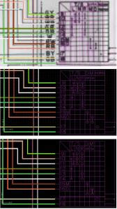
Hi Timo, What software are you using to trace. I started tracing, but found it was not so neat as I wanted. Ended up using the original as a tamplate in AutoCAD. With EndSnap, Grid and Polylines its easy to connect the parts and everything stays neat and tidy. I know DraftSight from Dassault systems works very similar to AutoCAD, but its lousy in Paperspace. NanoCAD works good in paperspace, but not so good as DraftSight in other areas. Here are some screen shots in stages. Background JPEG, Grid on & Grid off.
-
Steve,Are these caps the same size as the ones used on the ballast resistor? Can they be sent as normal post? I have sent small items like this overseas through the post a lot with no hassles. If I can keep the thickness under 32mm it costs €3.25 plus a bubble envelope. Thanks Chas
-
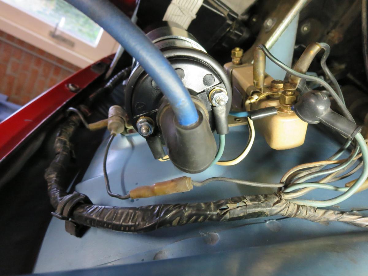
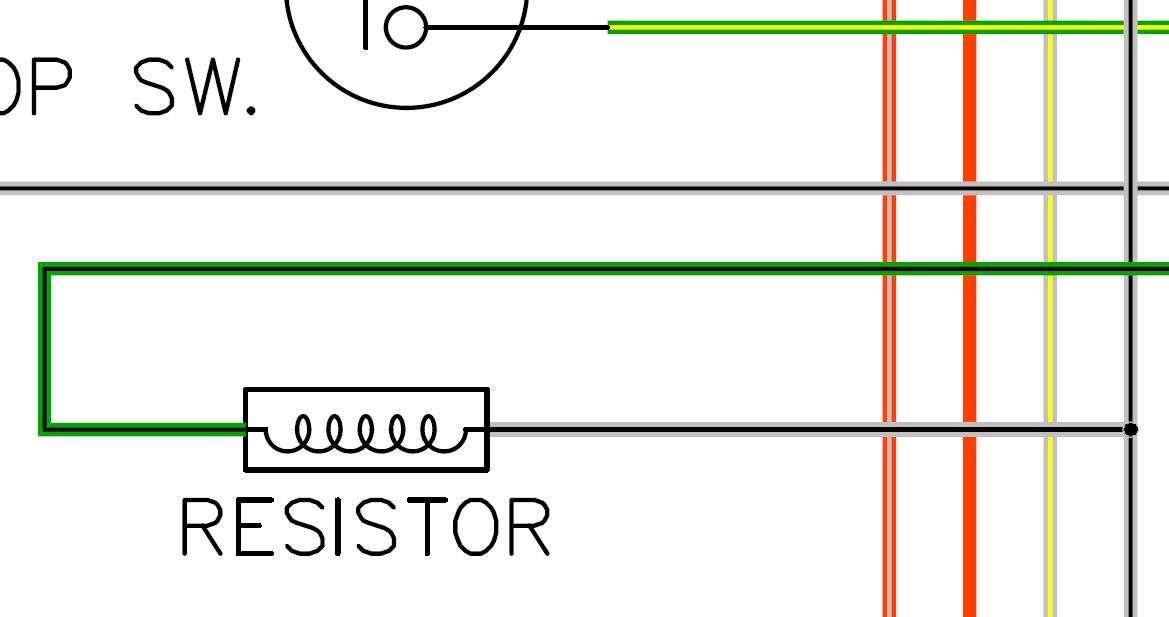
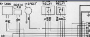
I think its something to do with the high beam headlights you use when passing or flashing another car. If you trace the wiring it runs through the combination switch and goes to the headlights. Its not on all the wiring diagrams you see on all the websites. Thats why Im asking about it.Did the early 240Z have the flash headlight function by pulling the comb.switch towards the steering wheel or am I missing something? You can see it in the "Colorwiring240zConcept " top left corner next to the engine bay inspection light. Chas
-
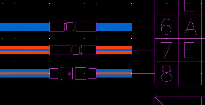
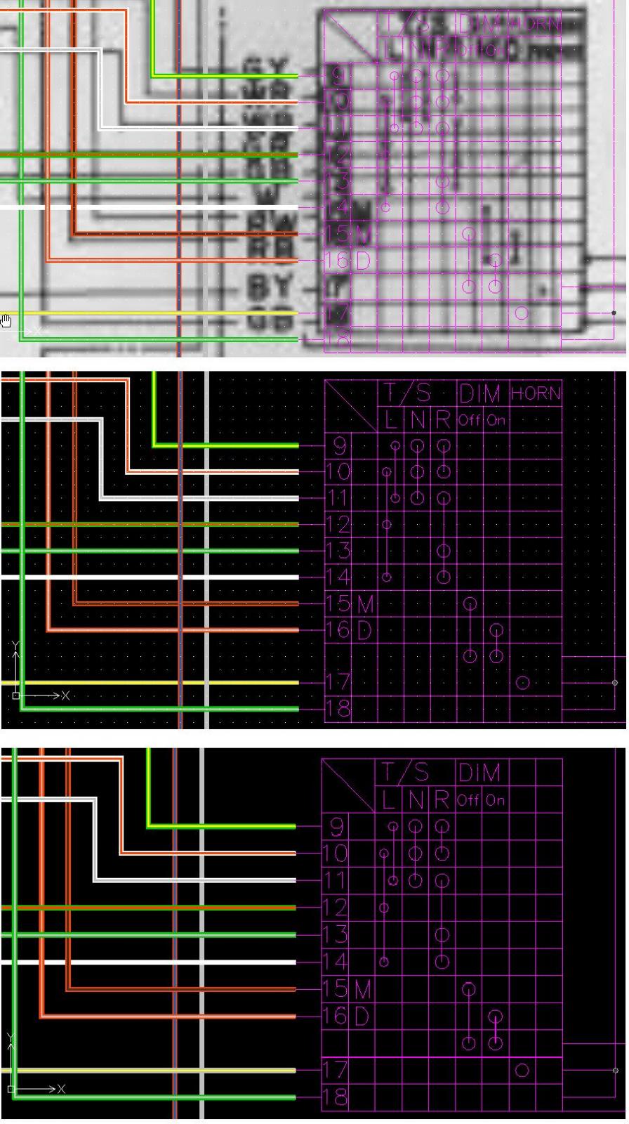
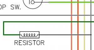
Update (Concept 20feb2015). Corrected some wiring color mistakes around the Tacho and Combination switch. Does anybody have information on the "PASSING RELAY" See screenshot. Its on the original wiring diagram I traced. A lot of diagrams don't have it so it seems to be some kind of option or a later addition. Lastly, verifying the wiring to the ballast resistor for the coil. One side is Green with white stripe, but the side coming from the ignition ON is shown in different colours on other "Color wiring diagrams". I have it as White with Black stripe. ColorWiring240Z1971_Concept 20-feb-2015.pdf
-
Here is a little update, still messing around with the layout a bit. moving things around to get a better fit with the wiring spaces. Ill add the colour key later. Blue can you point out what this would look like or a drawing with it complete and ture? Chris: Im looking at using adobe to switch off layers. This will enable you to switch off the A/T circuits etc. Make it easier to trace wiring in the circuits. For now its just finishing what I started. Steve: Draftsight is great software for home users. It has limitations in paper space. If you are using paperspace NanoCAD is beter. Chas ColorWiring240Z1971_Concept 19-feb-2015.pdf