


Captain Obvious
Free Member
-
Joined
-
Last visited
Everything posted by Captain Obvious
-
 @Mike
@Mike -
I think we always lose control of it. All we can hope for is that science fiction is just that.... fiction. Star Trek ("The Ultimate Computer" for example) Matrix Terminator I Robot Ex Machina
-
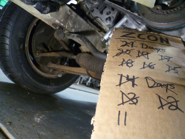
Countdown!!
-
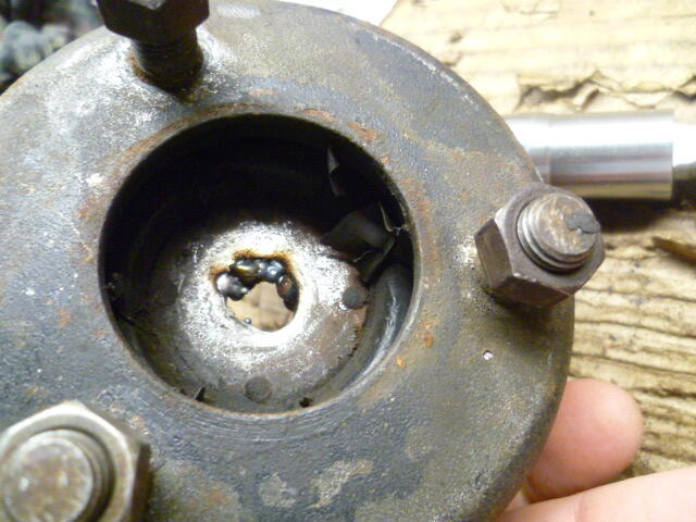
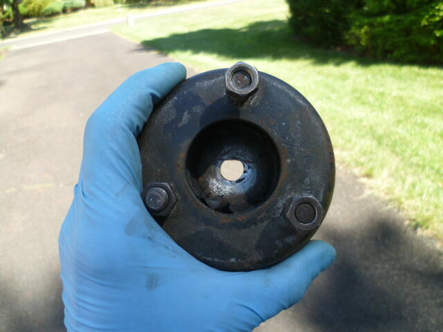
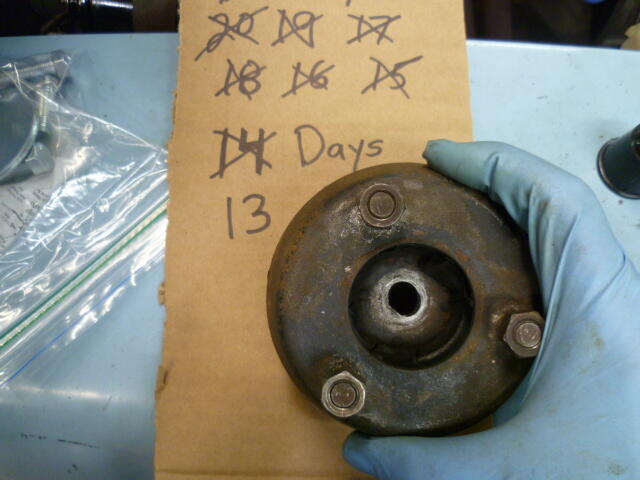
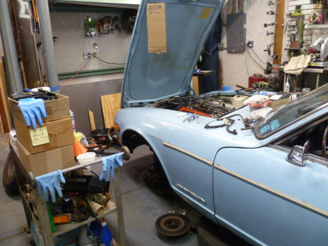
So with the help of some kind generous people from here on the forum, the front struts are back in the car! Here's a recap... I "welded" a couple dots down inside what was left of that "D" shaped hole. Isn't pretty, but doesn't have to be. All it has to do is keep the strut insert shaft from spinning while you tighten the nut. Hard to weld down inside that pocket, but here's what I did: Then I filed the hole back into a "D" shape and ground off a little bit of excess proud of the surface, and in the end, I have this: When you get the contrast right with backlight, you can get a decent look at the "D". Remember, all it has to do is keep the shaft from spinning: So with that crisis averted, put the struts back together. Put 'em on the car, reassemble and bleed the brakes, and I'm back to where I was two weeks ago*. Hahaha!! * But now I have struts that work.
-
Hahaha!! I'm hoping it won't come to that! ☺️
-
I thought I had pics of both flasher units (turn signal and hazards), but I can't find them. Memory says there are markings on the outsides of the cans that indicate how many filaments each one is designed for.
-
I wasn't there when they designed it, but my assumption would be the difference in the load that the two flasher units see. The turn signals are flashing four filaments (three in the rear and one in the front). While the flashers are seeing twice that (six in the rear and two in the front). The "off time" portion of the flasher unit is predominantly controlled by the load attached to the flasher unit. If that load is too small (like using LEDs), the off-time will be.... forever. If that load is too large, the off-time will be too short and the on-time will also longer than intended. The point is... The flasher needs to be matched accordingly to the load it is being used to control.
-
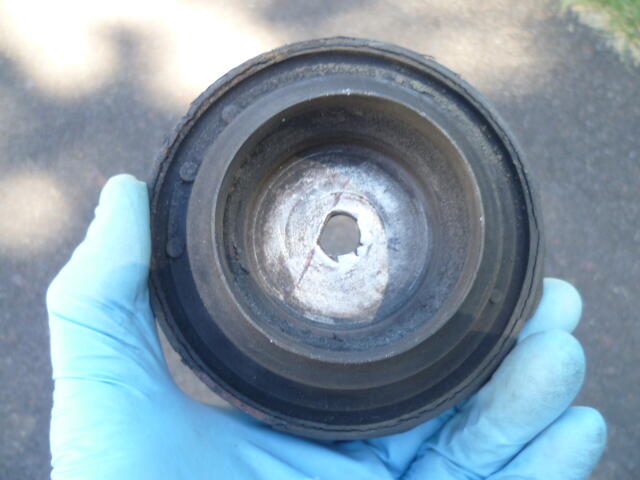
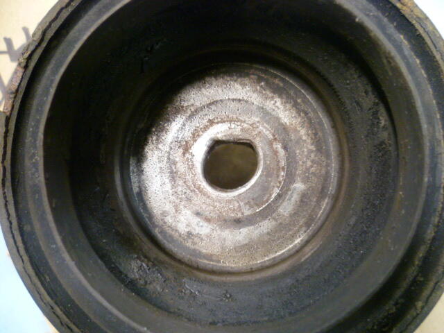
So I've been working on struts. Had a hard time getting the second one apart. Strut shaft kept turning in the "D" shaped hole. Got it apart and found this: Hoping I can dot a couple weld lumps in there to mitigate that issue. More news as it develops.
-
Thanks for the recommendation. I think my wipers work. My current plan is it's not going to rain while I'm on the road.
-
I've been maintaining a wiring diagram for the early cars. It's currently version 8, and you can find a copy here: https://www.classiczcars.com/forums/topic/69026-1970-wiring-diagram/page/7/?&_rid=23457#findComment-676548 It's not large or laminated, but it's accurate.
-
That is the accessory relay. On my mid-1970 car, that accessory relay sends power to the rear defroster and the heater blower. I don't know how frequently they were making changes to the wiring system, but I suspect your 1/71 is the same. Does any of that info matter to your turn signal issue? No. Haha!! ☺️
-
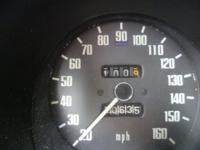
With the additional pics, I stand by the assessment that it's a Fall 1970 car with a rolled over odometer. It'a no "survivor" requiring a minor wash and buff. It's got all the wear and modifications and aftermarket parts that are typical with such a car. Oh, and a poorly applied re-paint. The annoying part is that the seller knows that some of the major claims in his listing are false. And he hasn't changed it. I do think, however, if he cleaned it all up and took copious good quality pictures, it would do better. As it sits, I don't think it's going to sell. And I think the seller knows it. I think at this point, it has become a test. Just to see what happens. If I didn't know better and bought that car, and then found this thread later?? Man, I'd be upset.
-
Hmmm... Seems like it should be worth at least as much as the 10/70 "project" 1971 Datsun 240Z Series I Project that was on BAT a couple weeks ago. https://bringatrailer.com/listing/1972-datsun-240z-359/ That one went for over $13K with a non-matching engine and poorly installed replacement floor pans. I'm thinking If that "barn find" thing on ebay has the original engine and floors, it should be worth more than the one that went on BAT?
-
Yeah, there's all kinds of things wrong with the description of that car. At the top of my list (besides the build date) is the claim about original paint. In my humble opinion, we're looking at a 9/70 (probably titled as a 1971) 240Z wearing a poorly done repaint. Probably with 107K miles. Don't get me wrong... It certainly has great potential. But it's not a very early car barn find with original paint and just 7K miles.
-
And I'm probably going to end up with a generic powder fire extinguisher. Yes, they are messy, but they're so ubiquitous and easy to get. I'm thinking if things get dire enough that I have to use it, the last thing I'm going to be concerned with is the mess.
-
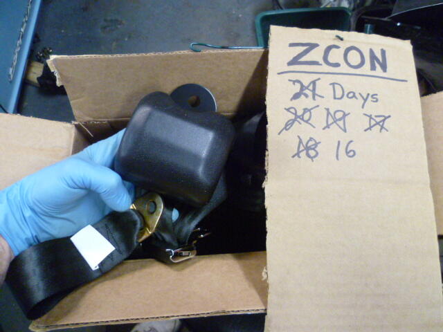
Still don't have the strut fiasco solved yet, but seat belts arrived!!
-
Yeah, there was something wrong with the forum. Wasn't working properly, but it seems to be back now.
-
Exactly. I'm not bemoaning the good deed that I did, but the delay is really putting a damper on my shakedown time!
-
Nothing special. Just KYB gas. The really silly part is that I HAVE a set of KYB's here already. The plan for them was to put them on my 77 280 as part of a project I have planned for that car. But since I was working on this 240 and running out of time, I figured I would use those KYBs on the 240 and then buy another new pair when I was ready to move forward with the 280 work. So.......... I tear the 240 apart. Break one strut down and get the old cartridge out of it. Open the KYB box I have here, and......... There inside the KYB box is a note. In my own handwriting. I sent the small gland nuts to another Z guy some couple of years ago because I wasn't going to be using them. I need the big ones for the 280 and I didn't own a 240 at the time. The small gland nuts were surplus to me and someone else needed a pair. So I sent them away. Aaaaaaarrrrrghh!!!!!
-
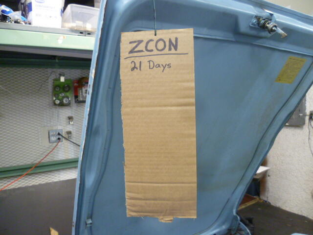
Countdown continues. I'm still waiting for struts. Not ideal. I need to get more miles on this thing to see what else falls off before I drive 1000 miles!!!
-
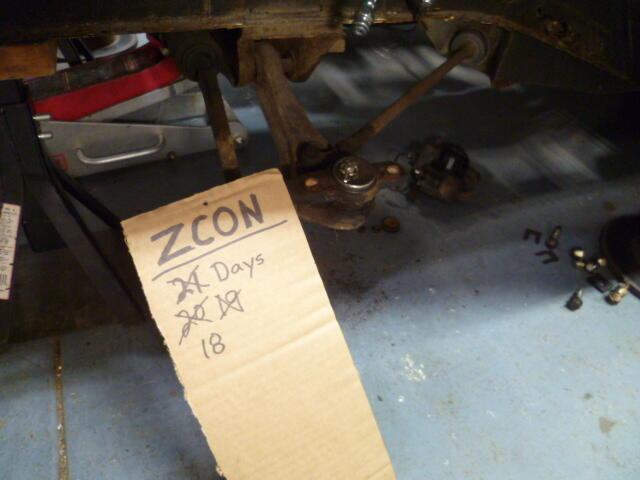
Countdown!! I got 100 miles on it: And those 100 test miles made it clear that I need front struts:
-
Sticky pistons on 4-screw round tops. Not ideal. About the only things that would account for that would be a) severely misaligned nozzles underneath or b) mismatched domes/pistons. You can check for the mismatching between the domes and pistons by taking the domes off, pulling the pistons out of the carbs and then sliding the pistons into the domes and see if they move smooth and free (while the dome and piston are in your hand, not mounted to the carb body). And you can check for misaligned nozzles/needles by either removing the needles out of the pistons, or by loosening up the nozzle alignment nuts on the under sides the carbs and seeing if the pistons move free while the nozzles are way loose.
-
Hope everything is dry now and your leak is all fixed up!
-
Sometimes new seals come with some little dabs of lube already on the inside lip. If yours did not, you can just use motor oil, or my favorite... silicone grease. As for the outside surface, I would do the same there. Motor oil or silicone grease. I wouldn't use anything that sticks like the aviation permatex. In my experience, the outside of the seal has significant interference with the hole you press it into. In fact, I've had to hit them harder than I was comfortable with just to get them seated into place. If your experience is like mine, you'll be thankful for the slippy on the OD, not the sticky. Use your old seal as a protection ring to tap your new one into place. And make sure the new one is square when you are done.
-
I wouldn't have any problem reusing that clutch. I'd replace the seal and reuse everything else. Don't forget a little bit of new EP grease on the pilot bushing.


