Mikes Z car
Free Member
-
Joined
-
Last visited
Everything posted by Mikes Z car
-
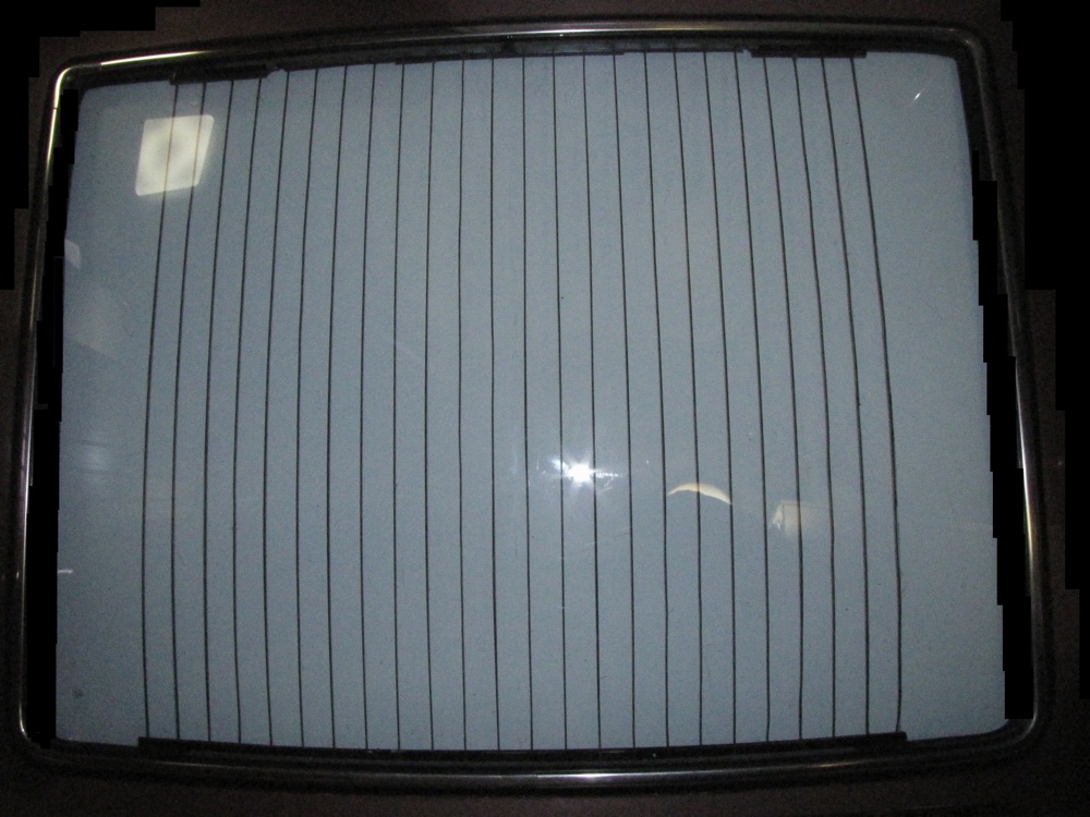
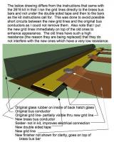
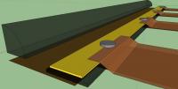
 I finished replacing the back hatch vertical defrost lines on my 240Z using the Frostfighter 2616 kit. I am not affiliated with Frostfighter in any way. http://www.frostfighter.com/prt2600.htm The 240Z hatch glass is too narrow for the 2616 kit as sold because the kit requires a minimum glass width of 40 inches. This is easily overcome by increasing the number of runs used in the kit from 4 to 6. For a 240Z with vertical lines the kit can be installed with lines running up and down instead of sideways like the kit was designed for. I installed the new lines on top of the old ones since I could not remove the old ones. I used 4 lines for 6 runs giving 24 defroster grid lines, 4 more than stock for the vertical grid back hatch. If you use 3 lines per run for 6 runs this gives 18 total lines, two less than the original number of lines on a vertical grid 240Z. If you go the 18 line route the kit will provide enough bus bars and other material as is however I wanted to increase the total number of lines to 24 which required two additional bus bars which I made from the flat metal bar that came from the paper part of a hanging file folder. Be certain when cutting bus bars from the kit that you cut them so that the two connectors on the short bus bars are at the top outside for the car wiring to access. The hanging file bars solder well, cut easily with tin snips and are the same thickness as the bus bars that come with the kit though a bit narrower. I attached those with double sided carpet tape (must be better tape somewhere) though I used a tiny drop of epoxy at both ends of all bus bars for further mechanical security. I drew 4 lines on the outside of the hatch glass where the 4 new grid lines were going to go as a guide; two were on each side of the existing grid. I put the other new grid lines on top of the old ones. The high resistance of the failed existing grid lines guaranteed they would not interfere with the new lines and they don't interfere as indicated by consistent voltage measurements between adjacent bus bars at the top of the hatch while the grid is in operation. The installation process described here will also work on horizontal line 240Zs and 280Zs by installing the defrost lines horizontally, see drawings. I scraped off the existing grid lines and bus bars with a razor blade so that they looked shiny to make the adhesive stick better as I put new grid lines on top of the old lines and used double sided tape on top of the existing bus bars. I unrolled the four paper rolls with the conductors and re-rolled them the opposite way to take the curl out. I hung them by one end from the side of the fridge for further flattening. I taped popsicle sticks flat against the rubber where the bus bars were going to go to space the bars out from the rubber. This differs with the instructions which call for 1/4" spacing but I though the bus bars would look closer to stock if they were closer to the rubber. I taped colored post it paper to the hatch metal next to where the bus bars were going to go including gaps in the paper to correspond with gaps between the new bus bars to keep the location and length of the bus bars straight. I used four bars at the top and 3 at the bottom of the hatch. The 3 at the bottom and the 2 inside bars at the top were all the same size; just longer than the spacing of 8 existing grid lines. The 2 outside bus bars at the top were just longer than spanning 4 grid lines. I used the kit bus bars and finisher cover at the bottom of the hatch as the driver would see those in case the hanging file bus bars used at the top would not look as nice. The kit calls for installing the grid lines so they go under the bus bars but I did not do that to prevent the possibility of a short between the new grid lines and the existing bus bars. I could have put the grid lines under the new bus conductor bars as the instructions call for if I had moved the bars further from the edge of the glass to avoid possible contact with the old bus bars though this might not have looked as nice. I soldered all connections between the grid lines and the bus bars for a solid connection though the instructions do not call for this. I feel soldering these connections is a significant improvement in the installation process. I tested the installation by connecting the grid to a 12 volt power supply rated for 19 amps. The glass got hot enough all over the grid after 20 minutes that I did not want to leave my hands on it. I also verified proper current flow by measuring the voltage between adjacent bus bars at the top of the window to ensure consistent voltage reading; all 3 readings were about 4.1 volts. I have enough defroster grid line material left over to replace more than 5 entire grid lines should that be needed. Any repairs can be soldered as the grid lines are largely copper. 07 Tech info.txt

-
I never heard of the idea being used on a car but with two way radio equipment sometimes they use a small ferrite doughnut looking thing that the power wire is routed through a few times.
-
Removed back hatch to redo defroster grid. Scraped defroster grid lines with razor blade and discovered that those grids are really on there. While I can't get them off that way I noticed they are now very smooth and shiny so I plan to put the new grid lines on top of the old ones. With my finger I can barely detect that the original lines are still there they are so thin even though they are easy to see. The old ones have high resistance everywhere I measure so they should not cause shorting with the new lines.
-
Do you meant the flat pieces that are about 5X5 inches square and about 1/16 inch thick?
-
This is really a memory test for me but I remember reading someone tested the improvement in mileage/or coefficient of drag when headlight covers were installed on a 240Z and the improvement was .3, whether that was mileage improvement or coefficient of drag improvement I can't remember.
-
Thanks for sharing. You gotta admire that kind of yankee ingenuity.
-
I have wondered if replacements could be made from fiberglass body filler using the old ones as a mold or covering the old ones with aluminum duct tape and painting that flat black. I realize it would be a lot of work. I like the idea of trying to make things that are hard to find. I have a 240, don't know if this already possibly impractical idea would work on a 280.
-
I used to be an atheist but I gave it up for lent.
-
Bought my first Z in 1977 in Maine (71 240) though I was only there a year or two before moving to southern states. The salt damage was to the floorboards and the outer rear wheel wells primarily for me. I did body filler to work to get rid of the damage over the wheel well arches and later hand rubbed undercoat into the wheel well seams and elsewhere. For the floorboards I just put an old license plate over the biggest hole under my feet. Back then I didn't have access to the vast rust repair knowledge on this website otherwise I would still have that car.
-
SteveJ, The Frostfighter can use one gridline but as Zed Head said you would have to use resistors to limit current. If you make that one gridline long enough (160"-246") by zigzagging you don't need resistors. Soldering the gridlines to the bus bars should eliminate grid line failures. Zed Head you are right resistors could make almost any configuration work including doing the install as intended by Frostfighter. The 2616 kit comes with a 20A fuse though I already have a 20A fuse in the defroster circuit. It looked like that that is what it is for as the PO changed the wiring. I am amazed that it seems smaller gauge wires are allowed to handle more current in a car than what you would find in a house. 14 or 16 gauge gauge wires with a 20 A fuse? I don't understand that philosphy. Mike
-
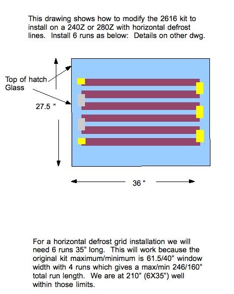
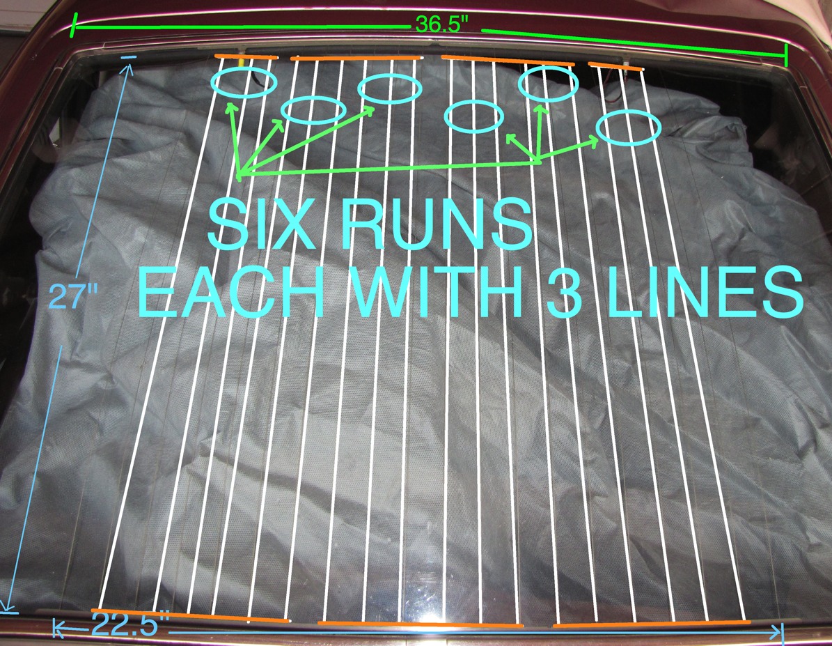
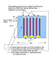
I am replacing the defroster grid on my 240Z with the vertical lines using the Frostfighter 2616 kit by turning the kit 90 degrees so it is vertical. Could someone please measure the current draw to a working rear defroster grid for a 240Z with vertical lines so I can verify the new installation won't overload the 240Z wiring? I plan on epoxying the brass bus bars to the glass instead of using the double sided tape provided and I plan on soldering all of the grid lines to the bus bars if that is practical. Also, the factory instructions call for 4 runs with 4 lines in each run with a minimum run length of 40" (and a max of 61.5") which is too big for a Z. To get around this I plan on six runs with 3 lines in each run to keep above the minimum run length total of 160" (4X40")- see drawing. On my car six runs will give 6X27" or 162". This will give 18 grid lines which are two less than stock however if I follow the kit plan for grid spacing between lines the width covered will wind up within 1/4" of the original defroster grid area. Turning this install idea 90 degrees so the lines are horizontal should make it fit a 280Z grid area as the total run length will then be 216" (6X36" the width of the back glass) which is within the maximum total run length of 246" (4X61.5"). Installing with six runs will require cutting the brass bus bars that come in the kit. My defroster grid is dead including the painted on bus bars. I figure solid metal conductors may last longer than the original grid. They make craft type narrow copper tape but I didn't want to try that. Thanks in advance for any assistance or ideas! Mike

-
If you wanted to use the prepared lines you would have to clean the adhesive off the side that faces the glass where they cross the bus bars at the top and bottom and I would think you would have to glue them to the bus bars with the versachem or other conductive paint. My grid lines are all bad and I am not sure the bus bars are good either. I get inconsistent test results with a volt/ ohmmeter. I want to start another thread on this, since I want to use the frostfighter repair system but need more information. Would you have to upgrade the wiring due to heavier current flow? Did they say what the current flow would be? If the current flow was too great would it be practical to put in a series resistor and if so where would one mount the resistor?
-
I asked the seller if the hatch grid lines were solid copper or painted on and he said they are solid copper. I wonder if they are the same as what frostfighter.com sells? I noticed the hatch defroster lines seemed wider and well defined compared to what is on my car but then the ones on my car don't work yet.
-
In the early 80s i was in Sydney Australia and lost about $900 in traveler's checks. They must have fallen out of my pocket while I was walking around. To get them replaced you have to report them lost to the police so I did. The policeman behind the counter asked me how much I had lost and what kind of traveler's checks. As I described what they were and the value he nonchalantly reached under the counter and threw them on the counter top. I was amazed as they hadn't been lost more than a few hours. I would always return a wallet.
-
I had an old Nash Metrpolitan (64?) that developed very stiff steering and the solution was to pump the driver's side lower ball joint with a lot of grease. Before that when the car was steered I could feel a momentary grab and let go many times as I turned and I could hear a clunk kind of noise. Mike
-
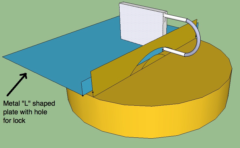
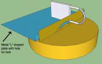
Looked at making a locking gas cap for my 240Z from an OEM gas cap without modifying it by putting in a metal insert and running a lock through it. If you use a small key lock like is used on a car cover it will fit through a gap in the top of the OEM gas cap handle without modifying it at least the one I have does. See picture for what the metal needs to look like. The piece of metal would need to be about two inches wide to prevent the gas cap from turning and would need to rest between the back of the gas cap area and the gas cap handle. Might have to put some rubber on the door and the metal insert to prevent the lock from banging on it. Should work and be very cheap to make though not as secure as an OEM locking cap I imagine. Mike
-
How are the two kinds different?
-
Great work and thanks for sharing the pictures! Mike
-
Is there a picture anywhere that is a closeup of the rubber and the metal molding and how they are put together? Both ends have a flat spot of metal, could that be drilled and a rod mounted all the way through (not sure it would help)? I have heard drilling stainless is a challenge. One of my squeegees does not contact the window at all; it appears to be too short.
-
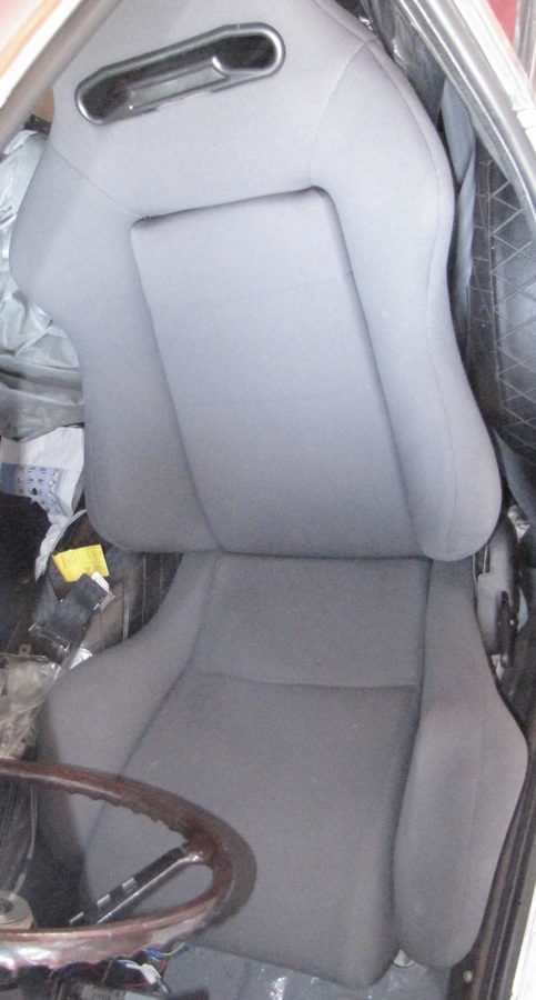
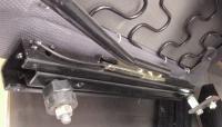
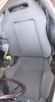
The PO installed the seats I have. Anyone know what they are? They have great lumbar support and are cloth covered though i don't particularly consider that an advantage. They have good side support to keep you from sliding around in a race though I don't do any racing and would probably be happy with something with good lumbar support without the side support. In case it helps someone else to know how to mount them I am including a picture of the mounting adapter. There are two new holes in the original front seat support in the car for the seats, I will edit this later to add info about any new holes in the rear original seat supports on the floor. Mike
-
My early 70 has a long blue fused wire that goes to the blower. The long black wire looks to me if I am seeing it right like a load (rear defroster?) because it is an exposed male connector and might short a power source to ground if left unplugged. That seems logical to me but may not be correct. Mike
-
grantf, Thanks for the idea of replacing only the damaged area, that is less intimidating than doing the whole valence panel. There are a couple of valences in the area I have access to though one is damaged the same place mine is (I haven't seen the other one yet). I should be able to weld in the new panel if not I know who can. You are right, the rear of the fender next to the valence is a little damaged but I think I can push that out from behind. Taking my time with this as you suggest should help quite a bit. 5thhorsemann, thanks for the thought. It doesn't take much of a ding in the sheetmetal to make a lot of work! Mike
-
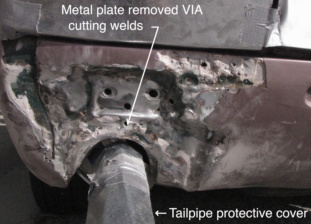
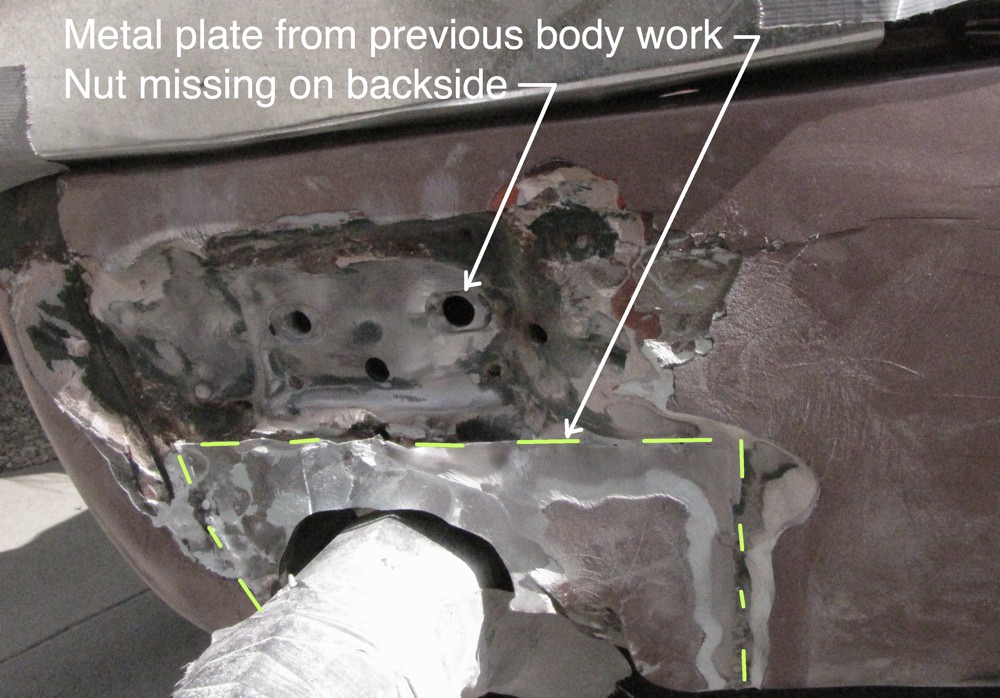
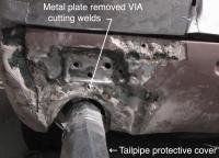
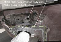
The car had two tailpipes side by side merged into one at the rear of the muffler when I got it with the original corners of the valence at the muffler's rear end bent back out of view and the welded on plate around the tailpipe hole I think was used to redefine the hole as squared off for the two tailpipes to go through. There are many holes in the valence around the tailpipe where the previous bodywork person used a slide hammer to pull out the valence. It didn't get pulled far enough out and that is why the bondo was 1/2" thick where the bumper mount bolt holes are. I took a 4 lb sledge to the back of the bumper mount point with a wooden drift where the two bolt holes for the bumper mount are to see if I could push it towards the rear of the car so the bolt hole surfaces are more flush with the valence surface like the other bumper mount. My reasoning is that if I can do this then the bondo needed then will be 1/4" max on the sheetmetal which I don't think will crack will it? The bondo that was on there had a crack in it I think because it was too thick. Anyone know how thick you can make bondo without it cracking? It may depend on what part of the car you put it as far as flexing? Replacing the valence is a little intimidating but may be possible even with my limited welding skills. Does the valence end under the license plate or does it go to the bottom edge of the hatch sill? What kind of grinder do you grind off the welds with, an angle grinder? I have read some drill them out. Thanks everyone for the great information. Mike
-
Pictures with metal plate from previous work removed and most of the bondo removed. Tank will have to come out I think.
-
Larry, Thanks for the information I appreciate your taking the time to share the details. I start taking off bondo today to see what is really there. I will post more pictures with the bondo off if it looks like it might be a good idea to put another set of eyes on this. Hopefully the mounting point bracket is all that got pushed forward, it looks like that might be the case since I can't see any obvious damage to the frame rail end though damage could still be hidden. Thanks for everyones ideas. Mike